diagram AUDI A6 ALLROAD 1999 C5 / 2.G Pneumatic Suspension System
[x] Cancel search | Manufacturer: AUDI, Model Year: 1999, Model line: A6 ALLROAD, Model: AUDI A6 ALLROAD 1999 C5 / 2.GPages: 44, PDF Size: 2.47 MB
Page 3 of 44
3
Contents
System description . . . . . . . . . . . . . . . . . . . . 4
The self-study programme is not intended as a workshop manual.
The self-study programme will provide you with information on
the design and functions of the different assemblies/systems.
New
NoteImportant:
Note
Page
For maintenance and repairs please refer to the current technical
literature.
Operation and display
Operation ................................................................................. 7
Display ..................................................................................... 8
Self-levelling suspension control unit J197 ....................... 34
Modes .................................................................................... 35
Control concepts
Service
Special tools .......................................................................... 38
Basic system settings .......................................................... 39
Self-diagnosis ....................................................................... 40
General overview .................................................................. 41
Control strategies
System components
Air springs .............................................................................. 14
Air suspension ...................................................................... 17
Diagram of pneumatic system ............................................. 20
Solenoid valves ...................................................................... 21
Temperature sensor G290..................................................... 22
Pressure sensor G291............................................................ 22
Level senders G76, G77, G78, G289 ..................................... 23
Warning lamp K134 ............................................................... 27
Operating unit E281 .............................................................. 28
CAN information exchange ................................................. 29
Additional interfaces ............................................................. 30
Function diagram ................................................................... 32
Interfaces
Control strategies, control unit 4Z7 907 553A ................... 10
Control strategies, control unit 4Z7 907 553B ................... 12
ESP safety switching ............................................................ 13
Order No.:
507.5320.01.00
This figure can be ordered as a size A0 poster through
Bertelsmann Distribution for a net price of DM
15.00 DM/7.50 EUR
.
Direct ordering through Bertelsmann only applies to Germany.
Dealers in export markets are requested to contact their importer.
Page 20 of 44
20
System components
p
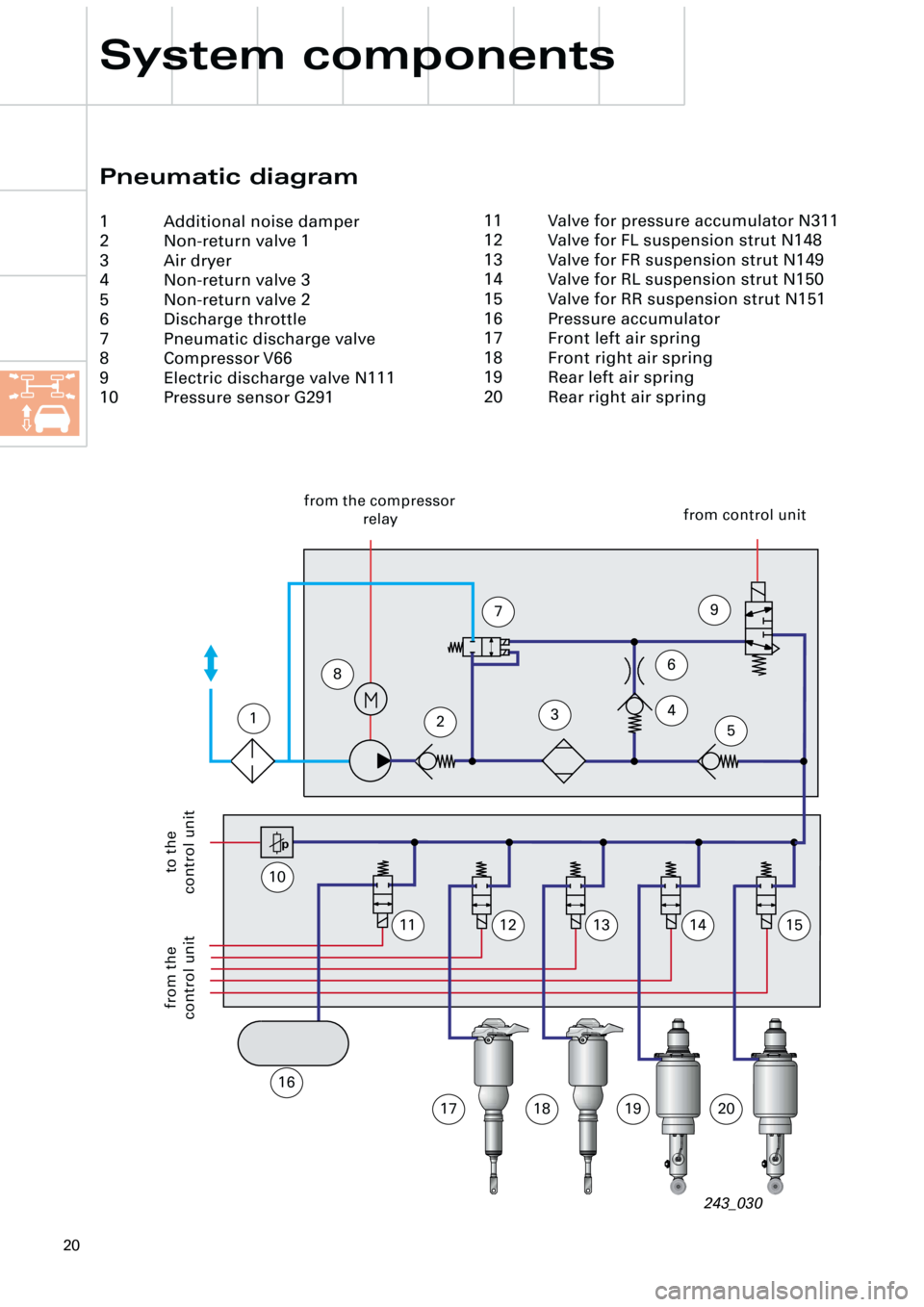
Pneumatic diagram
1 Additional noise damper
2 Non-return valve 1
3 Air dryer
4 Non-return valve 3
5 Non-return valve 2
6 Discharge throttle
7 Pneumatic discharge valve
8 Compressor V66
9 Electric discharge valve N111
10 Pressure sensor G291
243_030
1234
6
5
79
10
1112131415
16
17181920
11 Valve for pressure accumulator N311
12 Valve for FL suspension strut N148
13 Valve for FR suspension strut N149
14 Valve for RL suspension strut N150
15 Valve for RR suspension strut N151
16 Pressure accumulator
17 Front left air spring
18 Front right air spring
19 Rear left air spring
20 Rear right air spring
from the compressor
relay from control unit
to the
control unit from the
control unit
8
Page 32 of 44
32
Interfaces
pt° M
1
A
B
C
D
234
IVIIIIII
567
912
8
MM
31
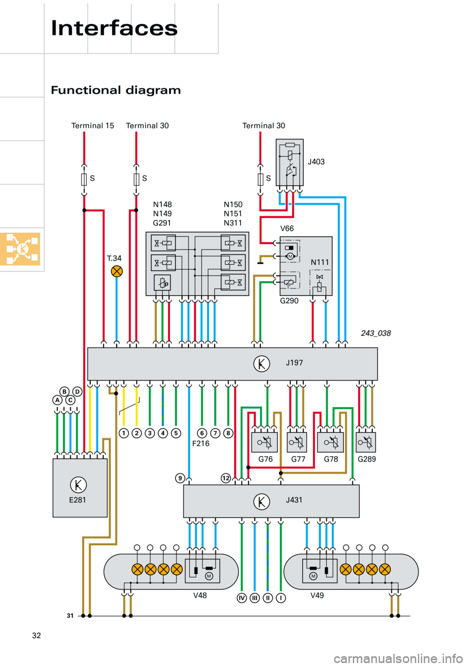
Functional diagram
Terminal 15 Terminal 30
T. 3 4Terminal 30
S S S
N150
N151
N311 N148
N149
G291
V66
G290N111
J197
G76 G77 G78 G289
J431
V48 V49 E281243_038 J403
F216
Page 33 of 44
33
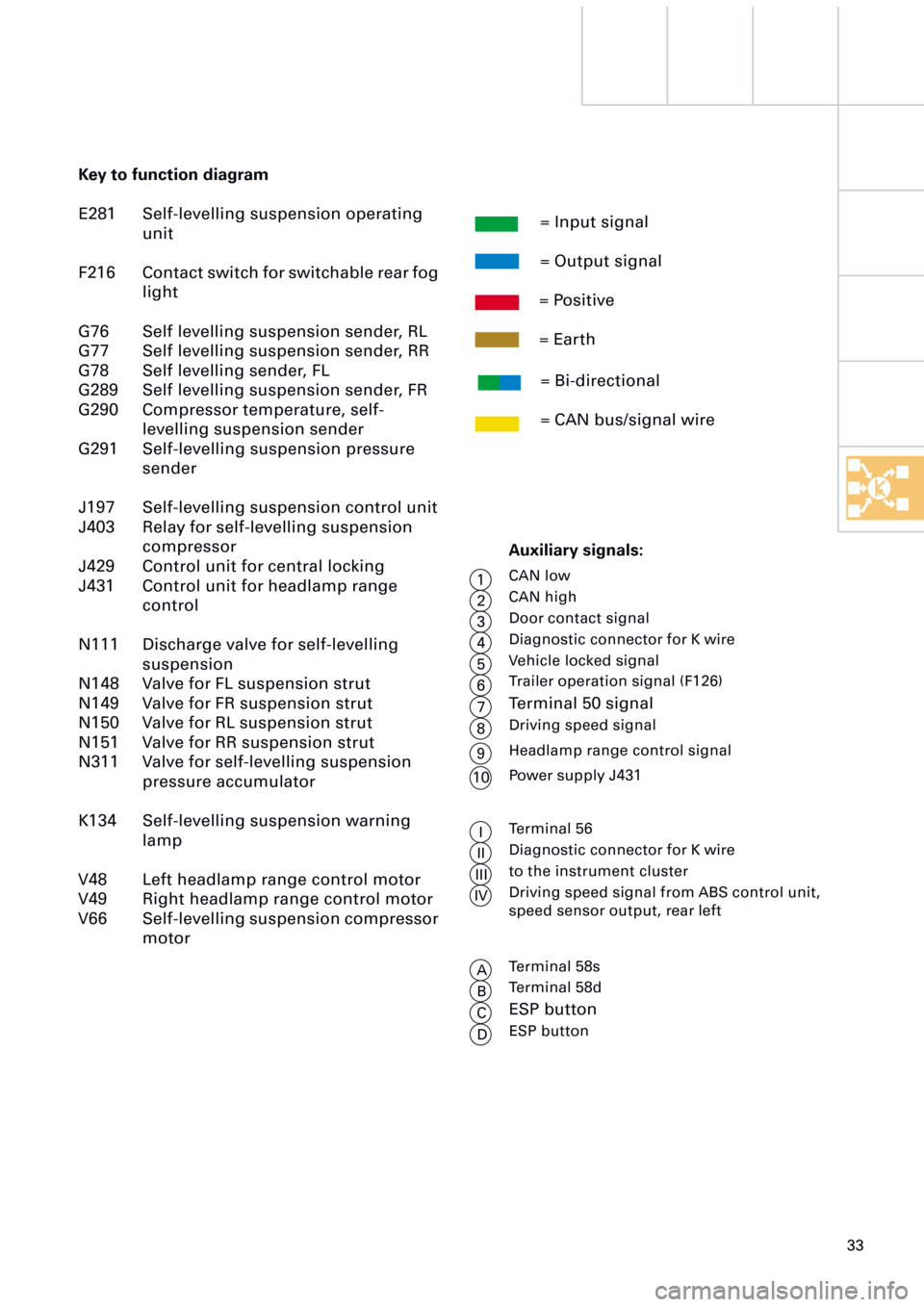
Key to function diagram
E281 Self-levelling suspension operating
unit
F216 Contact switch for switchable rear fog
light
G76 Self levelling suspension sender, RL
G77 Self levelling suspension sender, RR
G78 Self levelling sender, FL
G289 Self levelling suspension sender, FR
G290 Compressor temperature, self-
levelling suspension sender
G291 Self-levelling suspension pressure
sender
J197 Self-levelling suspension control unit
J403 Relay for self-levelling suspension
compressor
J429 Control unit for central locking
J431 Control unit for headlamp range
control
N111 Discharge valve for self-levelling
suspension
N148 Valve for FL suspension strut
N149 Valve for FR suspension strut
N150 Valve for RL suspension strut
N151 Valve for RR suspension strut
N311 Valve for self-levelling suspension
pressure accumulator
K134 Self-levelling suspension warning
lamp
V48 Left headlamp range control motor
V49 Right headlamp range control motor
V66 Self-levelling suspension compressor
motor= Input signal
= Output signal
= Positive
= Earth
= Bi-directional
= CAN bus/signal wire
Auxiliary signals:
CAN low
CAN high
Door contact signal
Diagnostic connector for K wire
Vehicle locked signal
Trailer operation signal (F126)
Terminal 50 signal
Driving speed signal
Terminal 56
Diagnostic connector for K wire
to the instrument cluster
Driving speed signal from ABS control unit,
speed sensor output, rear left
1
2
3
4
5
6
7
8
I
II
III
IV
Terminal 58s
Terminal 58d
ESP button
ESP button
A
B
C
DHeadlamp range control signal
9
Power supply J431
10
Page 34 of 44
34
However, all level sensors (left and right) are
required in the air suspension system run-up
and run-on mode (ignition OFF).
To allow the left-hand level sensors to deliver
measured values in the case of the 4-level air
suspension in the allroad quattro, power is
supplied to control unit J431 (HRC) from
control unit J197).
This ensures that voltage is supplied to all
level sensors when control unit J197 is active.
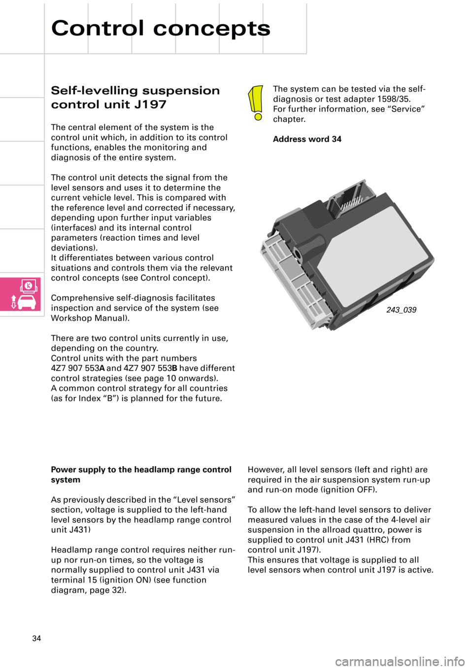
Self-levelling suspension
control unit J197
The central element of the system is the
control unit which, in addition to its control
functions, enables the monitoring and
diagnosis of the entire system.
The control unit detects the signal from the
level sensors and uses it to determine the
current vehicle level. This is compared with
the reference level and corrected if necessary,
depending upon further input variables
(interfaces) and its internal control
parameters (reaction times and level
deviations).
It differentiates between various control
situations and controls them via the relevant
control concepts (see Control concept).
Comprehensive self-diagnosis facilitates
inspection and service of the system (see
Workshop Manual).
There are two control units currently in use,
depending on the country.
Control units with the part numbers
4Z7 907 553A and 4Z7 907 553B have different
control strategies (see page 10 onwards).
A common control strategy for all countries
(as for Index “B”) is planned for the future.
Control concepts
243_039
The system can be tested via the self-
diagnosis or test adapter 1598/35.
For further information, see “Service”
chapter.
Address word 34
Power supply to the headlamp range control
system
As previously described in the “Level sensors”
section, voltage is supplied to the left-hand
level sensors by the headlamp range control
unit J431)
Headlamp range control requires neither run-
up nor run-on times, so the voltage is
normally supplied to control unit J431 via
terminal 15 (ignition ON) (see function
diagram, page 32).