oil AUDI A6 ALLROAD 1999 C5 / 2.G Pneumatic Suspension System
[x] Cancel search | Manufacturer: AUDI, Model Year: 1999, Model line: A6 ALLROAD, Model: AUDI A6 ALLROAD 1999 C5 / 2.GPages: 64, PDF Size: 3.12 MB
Page 6 of 64
6
Principles
The suspension system
As ÓsupportingÓ components of the
suspension system, the suspension elements
form the connection between the wheel
suspension and the bodywork. This system is
complemented by the spring action of the
tyres and vehicle seats.
The suspension elements include steel
springs, gas/air and rubber/elastomers or
combinations of the above.
Steel spring suspensions have become well
established in passenger vehicles. Steel
springs are available in a wide variety of
designs, of which the coil spring has become
the most widespread.
Air suspension, which has been used for
many years in heavy goods vehicles, is
Þnding increasing application in passenger
vehicles due to its system-related
advantages.
242_047
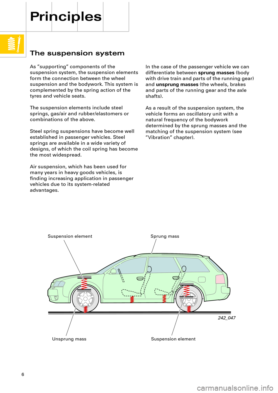
In the case of the passenger vehicle we can
differentiate between
sprung masses
(body
with drive train and parts of the running gear)
and
unsprung masses
(the wheels, brakes
and parts of the running gear and the axle
shafts).
As a result of the suspension system, the
vehicle forms an oscillatory unit with a
natural frequency of the bodywork
determined by the sprung masses and the
matching of the suspension system (see
ÓVibrationÓ chapter).
Sprung mass
Unsprung mass Suspension element
Suspension element
Page 12 of 64
12
00
Characteristic values of
springs
Characteristic curve/spring rate of springs
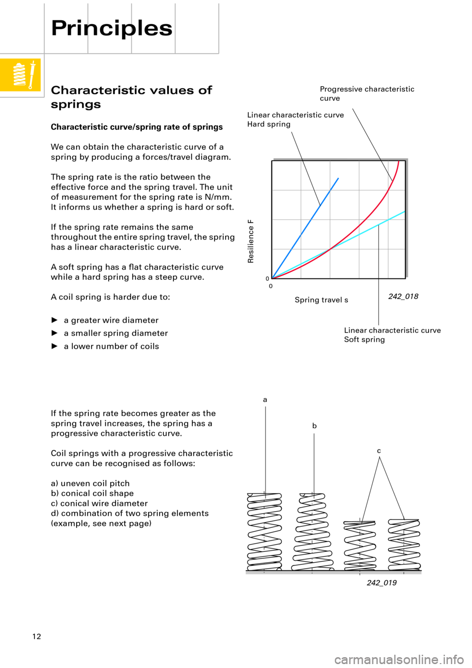
We can obtain the characteristic curve of a
spring by producing a forces/travel diagram.
The spring rate is the ratio between the
effective force and the spring travel. The unit
of measurement for the spring rate is N/mm.
It informs us whether a spring is hard or soft.
If the spring rate remains the same
throughout the entire spring travel, the spring
has a linear characteristic curve.
A soft spring has a ßat characteristic curve
while a hard spring has a steep curve.
A coil spring is harder due to:
¥ a greater wire diameter
¥ a smaller spring diameter
¥ a lower number of coils
Principles
242_018
If the spring rate becomes greater as the
spring travel increases, the spring has a
progressive characteristic curve.
Coil springs with a progressive characteristic
curve can be recognised as follows:
a) uneven coil pitch
b) conical coil shape
c) conical wire diameter
d) combination of two spring elements
(example, see next page)
242_019
Spring travel s
Resilience F
Linear characteristic curve
Hard spring
Progressive characteristic
curve
a
b
c Linear characteristic curve
Soft spring
Page 19 of 64
19
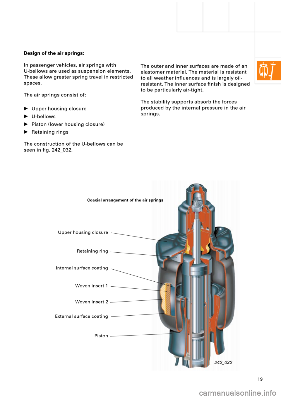
Design of the air springs:
In passenger vehicles, air springs with
U-bellows are used as suspension elements.
These allow greater spring travel in restricted
spaces.
The air springs consist of:
¥ Upper housing closure
¥ U-bellows
¥ Piston (lower housing closure)
¥ Retaining rings
The construction of the U-bellows can be
seen in Þg. 242_032.
242_032
The outer and inner surfaces are made of an
elastomer material. The material is resistant
to all weather inßuences and is largely oil-
resistant. The inner surface Þnish is designed
to be particularly air-tight.
The stability supports absorb the forces
produced by the internal pressure in the air
springs.
Upper housing closure
Retaining ring
Internal surface coating
Woven insert 1
Woven insert 2
External surface coating
Piston
Coaxial arrangement of the air springs
Page 25 of 64
25
Shock absorbers (vibration
dampers).
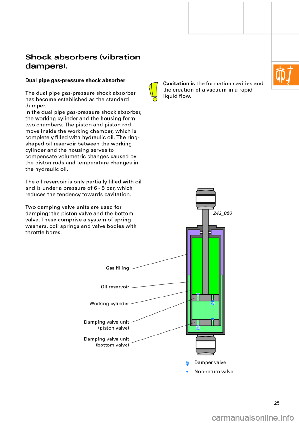
Dual pipe gas-pressure shock absorber
The dual pipe gas-pressure shock absorber
has become established as the standard
damper.
In the dual pipe gas-pressure shock absorber,
the working cylinder and the housing form
two chambers. The piston and piston rod
move inside the working chamber, which is
completely Þlled with hydraulic oil. The ring-
shaped oil reservoir between the working
cylinder and the housing serves to
compensate volumetric changes caused by
the piston rods and temperature changes in
the hydraulic oil.
The oil reservoir is only partially Þlled with oil
and is under a pressure of 6 - 8 bar, which
reduces the tendency towards cavitation.
Two damping valve units are used for
damping; the piston valve and the bottom
valve. These comprise a system of spring
washers, coil springs and valve bodies with
throttle bores.
242_080
Cavitation is the formation cavities and
the creation of a vacuum in a rapid
liquid ßow.
Working cylinder
Gas Þlling
Damping valve unit
(piston valve)
Damping valve unit
(bottom valve)
Oil reservoir
Damper valve
Non-return valve
Page 26 of 64
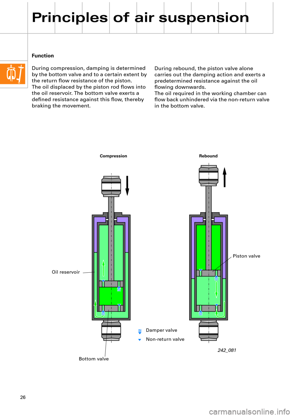
26
Principles of air suspension
During rebound, the piston valve alone
carries out the damping action and exerts a
predetermined resistance against the oil
ßowing downwards.
The oil required in the working chamber can
ßow back unhindered via the non-return valve
in the bottom valve. Function
During compression, damping is determined
by the bottom valve and to a certain extent by
the return ßow resistance of the piston.
The oil displaced by the piston rod ßows into
the oil reservoir. The bottom valve exerts a
deÞned resistance against this ßow, thereby
braking the movement.
242_081
Rebound Compression
Bottom valve
Oil reservoir
Piston valve
Damper valve
Non-return valve
Page 27 of 64
27
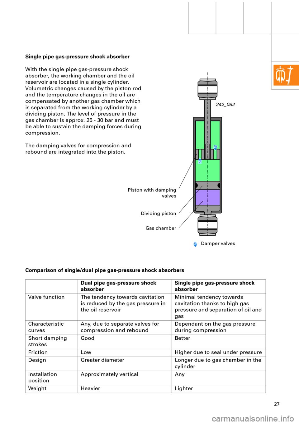
Single pipe gas-pressure shock absorber
With the single pipe gas-pressure shock
absorber, the working chamber and the oil
reservoir are located in a single cylinder.
Volumetric changes caused by the piston rod
and the temperature changes in the oil are
compensated by another gas chamber which
is separated from the working cylinder by a
dividing piston. The level of pressure in the
gas chamber is approx. 25 - 30 bar and must
be able to sustain the damping forces during
compression.
The damping valves for compression and
rebound are integrated into the piston.
Comparison of single/dual pipe gas-pressure shock absorbers
Dual pipe gas-pressure shock
absorberSingle pipe gas-pressure shock
absorber
Valve function The tendency towards cavitation
is reduced by the gas pressure in
the oil reservoirMinimal tendency towards
cavitation thanks to high gas
pressure and separation of oil and
gas
Characteristic
curvesAny, due to separate valves for
compression and reboundDependant on the gas pressure
during compression
Short damping
strokesGood Better
Friction Low Higher due to seal under pressure
Design Greater diameter Longer due to gas chamber in the
cylinder
Installation
positionApproximately vertical Any
Weight Heavier Lighter
242_082
Piston with damping
valves
Dividing piston
Gas chamber
Damper valves
Page 28 of 64
28
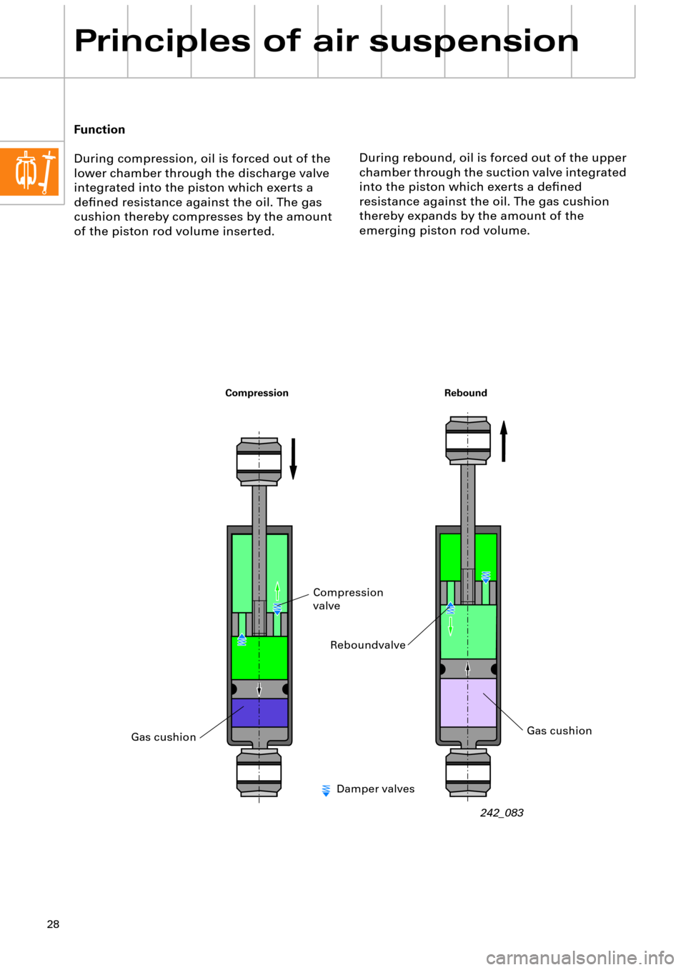
Principles of air suspension
During rebound, oil is forced out of the upper
chamber through the suction valve integrated
into the piston which exerts a deÞned
resistance against the oil. The gas cushion
thereby expands by the amount of the
emerging piston rod volume. Function
During compression, oil is forced out of the
lower chamber through the discharge valve
integrated into the piston which exerts a
deÞned resistance against the oil. The gas
cushion thereby compresses by the amount
of the piston rod volume inserted.
242_083
Rebound Compression
Gas cushion
Reboundvalve
Compression
valve
Gas cushion
Damper valves
Page 31 of 64
31
0,52 0,260
-0,26-0,52
0,52 0,260
-0,26-0,52
0,52 0,260
-0,26-0,52
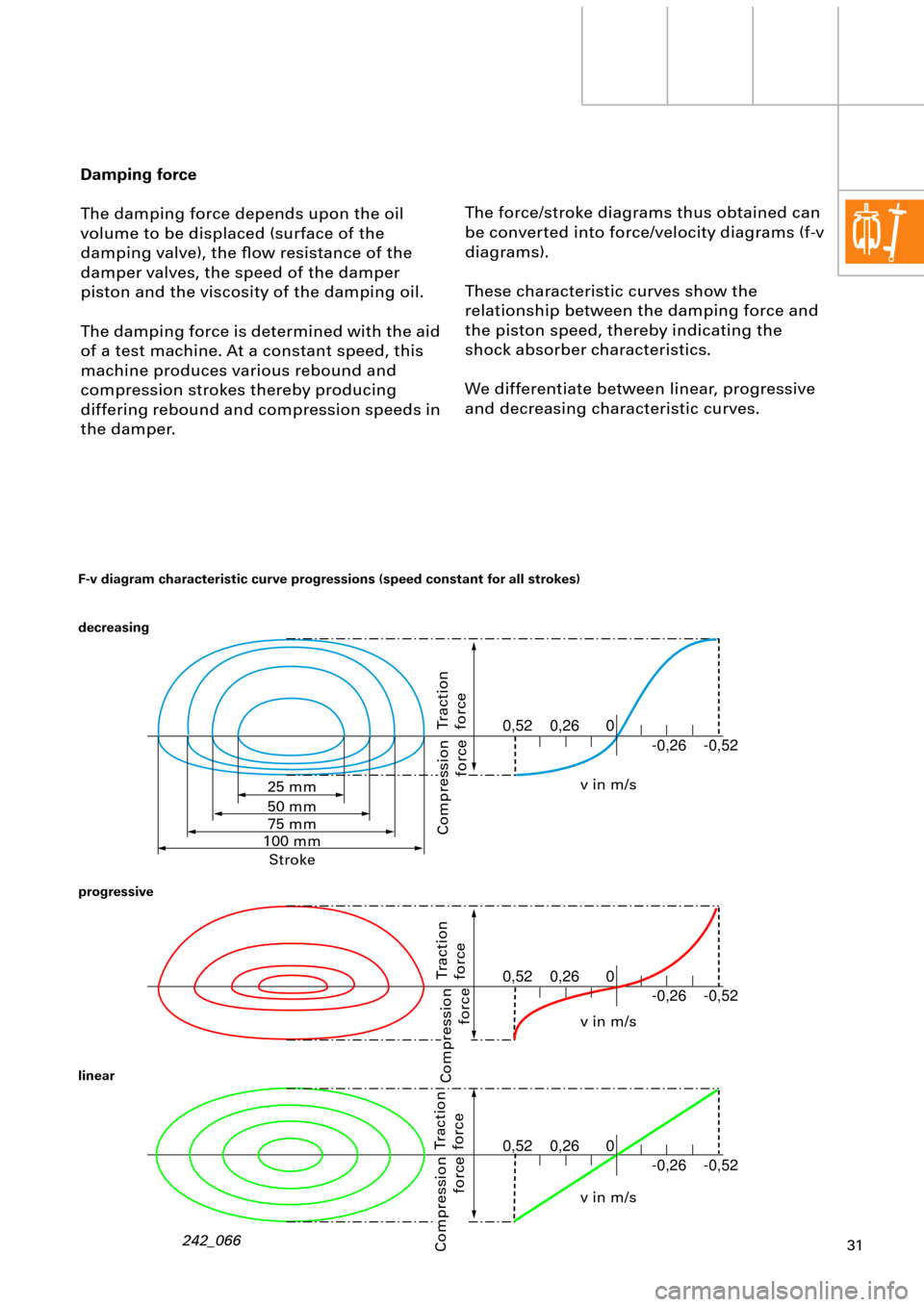
The force/stroke diagrams thus obtained can
be converted into force/velocity diagrams (f-v
diagrams).
These characteristic curves show the
relationship between the damping force and
the piston speed, thereby indicating the
shock absorber characteristics.
We differentiate between linear, progressive
and decreasing characteristic curves. Damping force
The damping force depends upon the oil
volume to be displaced (surface of the
damping valve), the ßow resistance of the
damper valves, the speed of the damper
piston and the viscosity of the damping oil.
The damping force is determined with the aid
of a test machine. At a constant speed, this
machine produces various rebound and
compression strokes thereby producing
differing rebound and compression speeds in
the damper.
242_066
F-v diagram characteristic curve progressions (speed constant for all strokes)
decreasing
progressive
linear
Traction
force
Compression
force
Traction
force
Compression
force
Traction
force
Compression
force
v in m/s
v in m/s
v in m/s 25 mm
50 mm
75 mm
100 mm
Stroke
Page 35 of 64
35
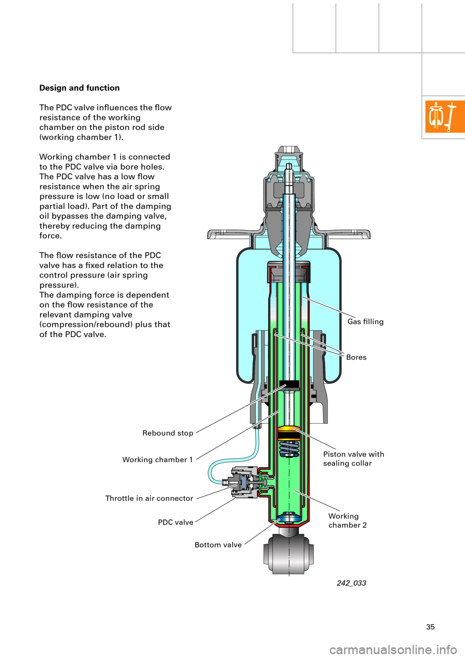
Design and function
The PDC valve inßuences the ßow
resistance of the working
chamber on the piston rod side
(working chamber 1).
Working chamber 1 is connected
to the PDC valve via bore holes.
The PDC valve has a low ßow
resistance when the air spring
pressure is low (no load or small
partial load). Part of the damping
oil bypasses the damping valve,
thereby reducing the damping
force.
The ßow resistance of the PDC
valve has a Þxed relation to the
control pressure (air spring
pressure).
The damping force is dependent
on the ßow resistance of the
relevant damping valve
(compression/rebound) plus that
of the PDC valve.
242_033 PDC valve Working chamber 1
Bottom valvePiston valve with
sealing collar
Working
chamber 2BoresGas Þlling
Throttle in air connectorRebound stop
Page 36 of 64
36
Principles of air suspension
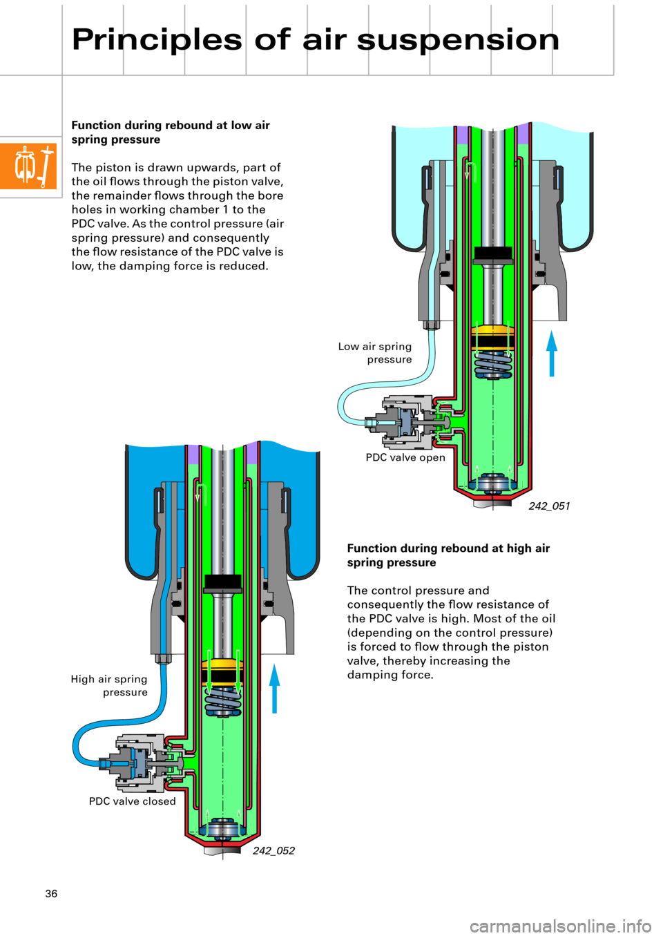
Function during rebound at low air
spring pressure
The piston is drawn upwards, part of
the oil ßows through the piston valve,
the remainder ßows through the bore
holes in working chamber 1 to the
PDC valve. As the control pressure (air
spring pressure) and consequently
the ßow resistance of the PDC valve is
low, the damping force is reduced.
242_052
242_051
Function during rebound at high air
spring pressure
The control pressure and
consequently the ßow resistance of
the PDC valve is high. Most of the oil
(depending on the control pressure)
is forced to ßow through the piston
valve, thereby increasing the
damping force.
Low air spring
pressure
High air spring
pressurePDC valve open
PDC valve closed