relay AUDI A6 ALLROAD 1999 C5 / 2.G Pneumatic Suspension System
[x] Cancel search | Manufacturer: AUDI, Model Year: 1999, Model line: A6 ALLROAD, Model: AUDI A6 ALLROAD 1999 C5 / 2.GPages: 64, PDF Size: 3.12 MB
Page 42 of 64
42
Self-levelling suspension, A6
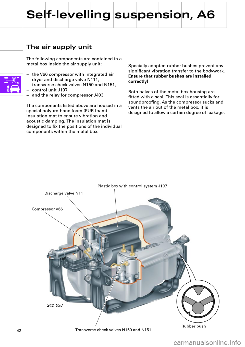
Specially adapted rubber bushes prevent any
signiÞcant vibration transfer to the bodywork.
Ensure that rubber bushes are installed
correctly!
Both halves of the metal box housing are
Þtted with a seal. This seal is essentially for
soundprooÞng. As the compressor sucks and
vents the air out of the metal box, it is
designed to allow a certain degree of leakage.
The air supply unit
The following components are contained in a
metal box inside the air supply unit:
Ð the V66 compressor with integrated air
dryer and discharge valve N111,
Ð transverse check valves N150 and N151,
Ð control unit J197
Ð and the relay for compressor J403
The components listed above are housed in a
special polyurethane foam (PUR foam)
insulation mat to ensure vibration and
acoustic damping. The insulation mat is
designed to Þx the positions of the individual
components within the metal box.
242_038Plastic box with control system J197
Discharge valve N11
Transverse check valves N150 and N151 Compressor V66
Rubber bush
Page 43 of 64
43
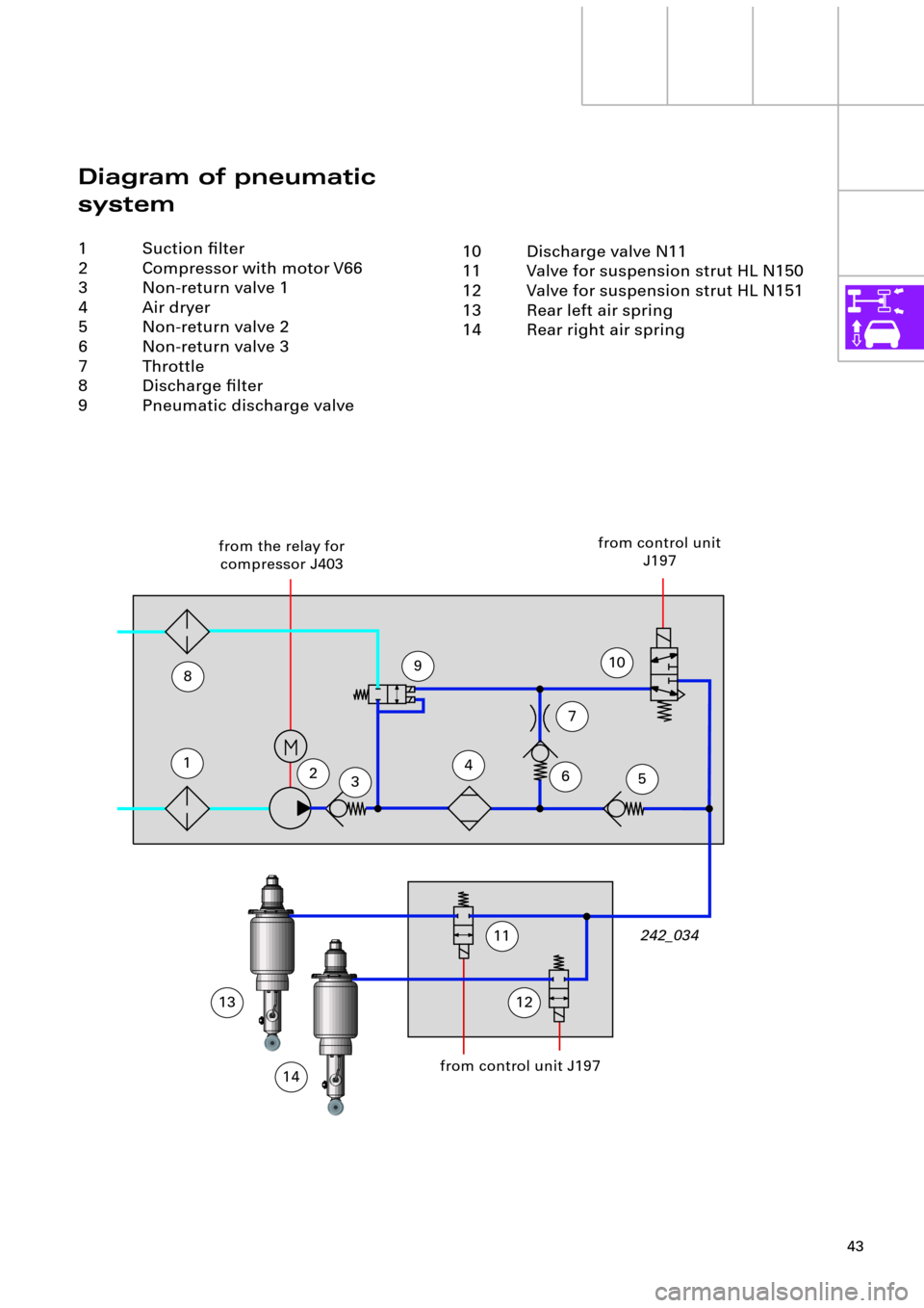
Diagram of pneumatic
system
1 Suction Þlter
2 Compressor with motor V66
3 Non-return valve 1
4 Air dryer
5 Non-return valve 2
6 Non-return valve 3
7 Throttle
8 Discharge Þlter
9 Pneumatic discharge valve
123
465
7
9
11
10 Discharge valve N11
11 Valve for suspension strut HL N150
12 Valve for suspension strut HL N151
13 Rear left air spring
14 Rear right air spring
from the relay for
compressor J403from control unit
J197
10
1213242_034
from control unit J197
14
8
Page 45 of 64
45
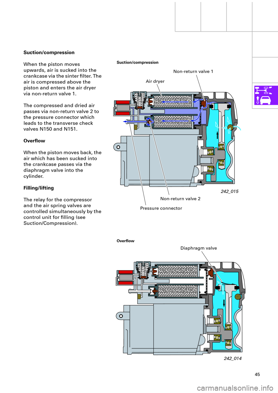
Suction/compression
When the piston moves
upwards, air is sucked into the
crankcase via the sinter Þlter. The
air is compressed above the
piston and enters the air dryer
via non-return valve 1.
The compressed and dried air
passes via non-return valve 2 to
the pressure connector which
leads to the transverse check
valves N150 and N151.
Overßow
When the piston moves back, the
air which has been sucked into
the crankcase passes via the
diaphragm valve into the
cylinder.
Filling/lifting
The relay for the compressor
and the air spring valves are
controlled simultaneously by the
control unit for Þlling (see
Suction/Compression).
242_015 Non-return valve 1
Air dryer
Pressure connectorNon-return valve 2
242_014 Diaphragm valve
Suction/compression
Overßow
Page 50 of 64
50
Self-levelling suspension, A6
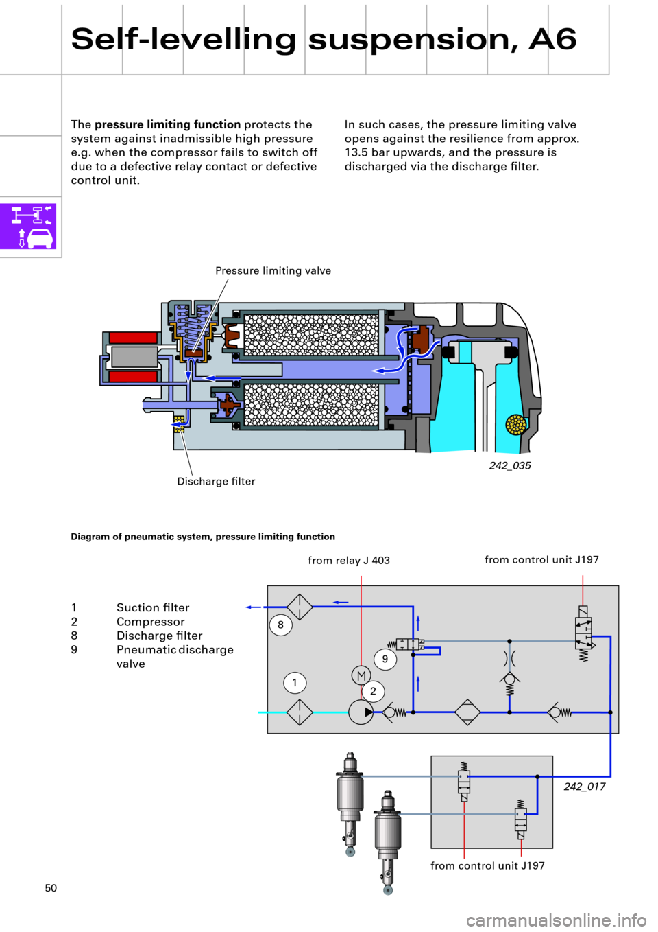
The pressure limiting function protects the
system against inadmissible high pressure
e.g. when the compressor fails to switch off
due to a defective relay contact or defective
control unit.
242_035
242_017
Diagram of pneumatic system, pressure limiting function
12
9
8
1 Suction Þlter
2 Compressor
8 Discharge Þlter
9 Pneumatic discharge
valve
from relay J 403
In such cases, the pressure limiting valve
opens against the resilience from approx.
13.5 bar upwards, and the pressure is
discharged via the discharge Þlter.
Pressure limiting valve
Discharge Þlter
from control unit J197
from control unit J197
Page 56 of 64
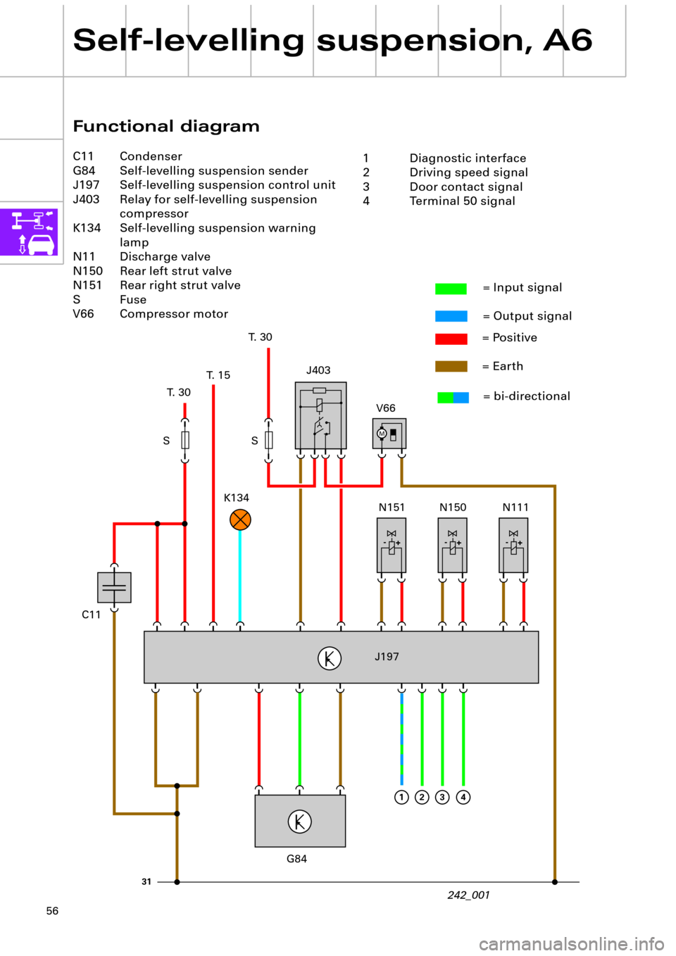
56
Self-levelling suspension, A6
M
+ -+ -+ -
31
1234
Functional diagram
C11 Condenser
G84 Self-levelling suspension sender
J197 Self-levelling suspension control unit
J403 Relay for self-levelling suspension
compressor
K134 Self-levelling suspension warning
lamp
N11 Discharge valve
N150 Rear left strut valve
N151 Rear right strut valve
S Fuse
V66 Compressor motor
T. 30T. 15T. 30
242_001 S SJ403
V66
N111 N150 N151 K134
J197
G84
= Input signal
= Output signal
= Positive
= Earth
= bi-directional
1 Diagnostic interface
2 Driving speed signal
3 Door contact signal
4 Terminal 50 signal
C11