display AUDI A7 2015 User Guide
[x] Cancel search | Manufacturer: AUDI, Model Year: 2015, Model line: A7, Model: AUDI A7 2015Pages: 316, PDF Size: 78.09 MB
Page 30 of 316
28 Instruments and warning /indicator lights
The schedule fo r the next oil change o r inspec
t ion is calculated automatically and d isplayed
according ly . T he display works in two stages :
Service reminder
30 days befo re the ne xt service is due, a serv
i ce rem inder appears in the di splay when yo u
switch the ignit ion on
¢ fig . 13.
Afte r abo ut 5 seconds the display sw itches
b ack to normal. The di sta nce and time re
maining a re update d eac h time the ignition is
switched on unt il the date due for service is
reac hed .
Service due
When the due date for service is reached , the
message
Service due! appears in the instr u
men t clus ter immedia tely after you switch the
i gnition on. Additionally, a war ning tone
sounds . After about 5 seconds the display
switches back to normal.
Calling up the service schedules
If o r whe n an oil change o r inspect ion is due,
can be shown in the MM I disp lay by select ing
the service interva l disp lay in the car menu .
Select the
! CAR ! function b utton> (Ca r)* s ys
tems
contro l button > Servicing & chec ks >
Service interval displays.
Resetting the service interval display
Your author ized A udi dealer w ill reset the cor
responding service sched ule after perform ing
the app rop riate serv ice on yo ur vehicle. Yo u
a ls o have the possibility to reset the oi l
change schedule after having performed an
oil change according to Audi specifications.
Selec t the
I CAR ! function button > (Car) * sys
tems
cont ro l button > Servicing & checks >
Service Intervals > Re set oil change interval.
(D Note
- Only reset the o il change d isp lay when
you hav e compl eted an o il change .
- If you d isconnect t he battery te rm inals,
no calc ulations can be made for the serv
i ce interv al display during this t ime and
n o servi ce re mi nder w ill appear . Reme m- ber th
at o bse rv ing the p roper service in
tervals is vita lly im po rtant to extend ing
the life of your vehicle, part icularly the
eng ine , and maintain ing its value. Eve n if
the mileage driven is low, the maxim um
p er iod of one year fro m one service to
t he next mus t not be e xceed ed .
@ Tips
The information in the Service Reminder
r ema ins sto red even when the vehicle bat
tery is disconnected.
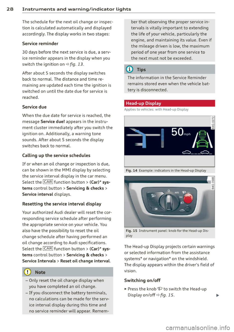
Head -up Display
Applies to veh icles: w ith Head-up D isp lay
Fig. 14 Exa mple: in dic ato rs in th e Head -up D isplay
Fi g. 1 5 Ins trume nt panel: k nob for t he Head -u p D is
play
The Head -up D isplay projects cer tain warnings
o r se lected info rmation from the ass istance
syste ms* or na vigatio n* on t he windsh ie ld .
T he disp lay appe ars wi thin the drive r's field o f
vision .
Switching on/off
.,. Press the knob 1rl to switch t he Head-up
Display o n/off ¢
fig. 15.
Page 31 of 316
M N <( I.J "". rl I.O
"' rl
"' rl
Instrument s and warning /indicator lights 29
Adjusting the height
The height of the display can be a djus ted to
t he individual driver .
.. Make sure you a re seated cor rect ly
¢page 129.
.. Turn the knob~ to adjust the displ ay .
Settings in the MMI
.. Se lect: I CARI funct ion button > ( Car )* s ys
tems
control button > D river Assist > Head
up Display > Head-up Display content
or
Di splay brightne ss .
Display content
In the MMI, you ca n specify which information
should be displayed :
- Cruise contro l system*
- Navigatio n information*
- A udi adaptive cruise control *
- Audi a ct ive lane assist*
- Night vis ion assistant*
The speed display and some of the red indica tor lights cannot be hidden in the MMI.
Display brightness
You can ad just the display brightness in t he
MMI. The display brightness decreases auto
mat ica lly as the amount of light decreases.
The basic leve l of brightness is adjusted with
the ins trumen t illum ina tion ¢ page 47 .
(D Note
To prevent sc ratches on t he g lass covering
the Head-up Disp lay, do not place any ob
jects in the proj ection opening.
(D Tips
- Sung lasses w ith polar izat ion fi lters an d
unfavorable lighting condit ions can af
fect the display.
- A specia l w indshield is needed for the
Head-up Display funct io n.
- Fo r information on cleaning, refer to
¢ table on page 214.
On-Board Diagnostic
system (OBD)
Malfunction Indicator Lamp (MIL )
The Ma lfunction Indicator Lamp ( MIL ) ¢'4 in
the instr ument cluster is part of the On-Board
Diagnostic (OBD II) system .
T he wa rni ng/indicator light ill uminates when
the ignit io n is switched on and goes out after
the engine sta rts and the id le has stab ilized.
This indicates that the MIL is working proper
ly .
If the light does not go out afte r th e en gine
is started, or illuminates while you are dr iv
ing, a mal function may exist in the engine sys
tem.
If the lig ht illum inates, the catalyt ic con
verter could be damaged .
Contin ue driving
with reduced power (avoid
ing s ustained high speeds and/or rapid accel
erations) and have the cond ition corrected.
Contact your aut horized Audi dea ler.
If the light illuminates, the e lectronic speed
limiter may also be malfunct ioning . For more
information
c> page 30, Electronic speed
limiter.
An improperly closed fuel filler cap may also
cause the MIL light to illuminate
c> page 219.
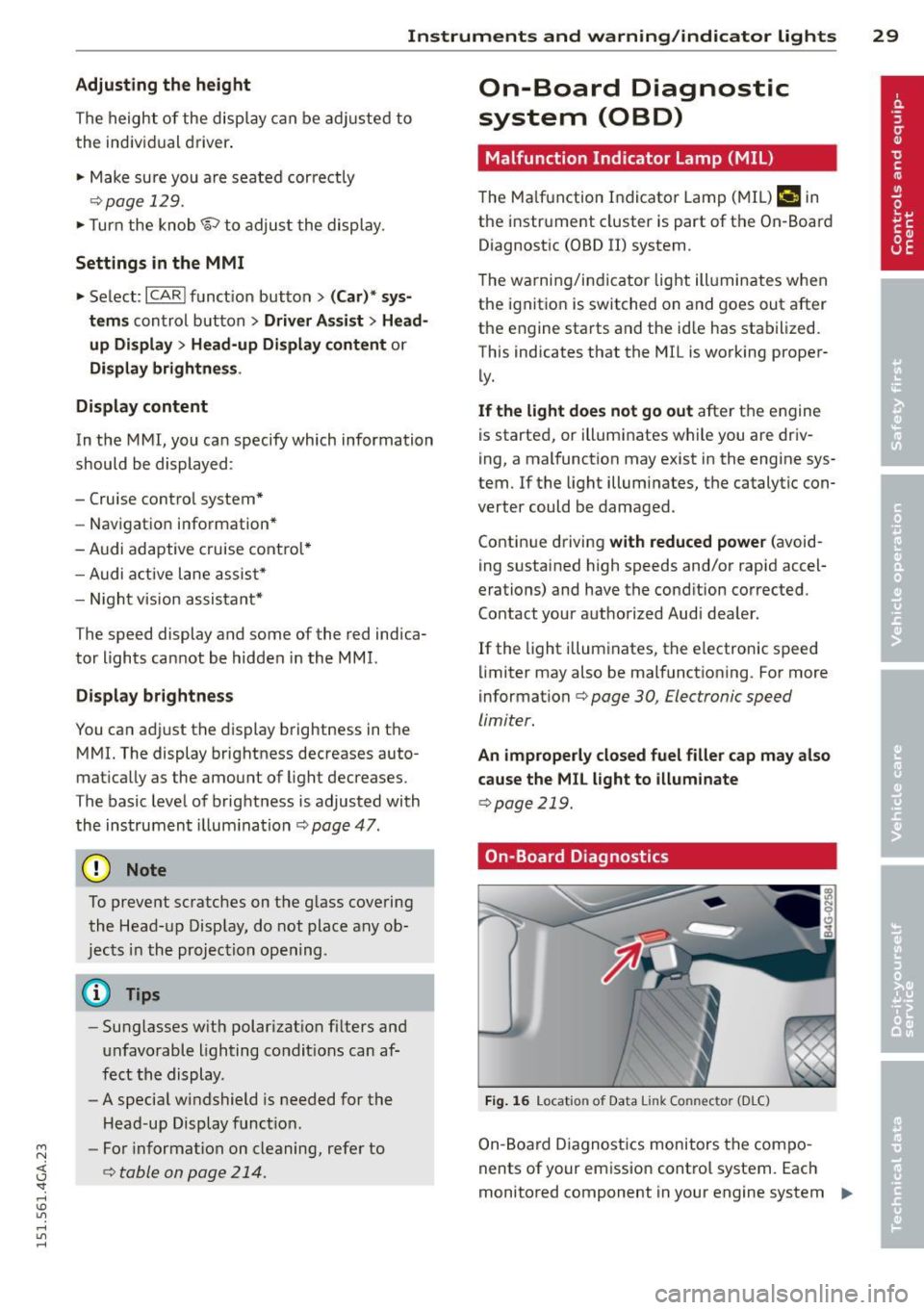
On-Board Diagnostics
Fig. 1 6 Location o f Data Li nk Co nnector (D LC)
On-Board Diagnostics monitors the com po
nents of your emission cont ro l system. Each
monitored component in your engine system
Iii>-
Page 32 of 316
30 Instruments and warning /indicator lights
has been assigned a code. In case of a ma l
function, the component will be identified
and the fault stored as a code in the contro l
module memory.
The MIL light may a lso illuminate if there is a
leak in the on-board fue l vapor recovery sys
tem .
If the light illuminates after a refue lling,
stop the vehicle and make sure the fuel filler
cap is properly closed ¢
page 219.
In order to make an accurate diagnosis, the
stored data can only be displayed using spe
cial diagnostic equipment (generic scan tool
for OBD) .
In order to connect the special diagnostic
equipment, push the plug into the Data L ink
Connector (DLC). The DLC is located to the
right of the hood release¢
fig. 16.
Your authorized Audi dealer or a qualified
service station can interpret the code and per
form the necessary repair .
A WARNING
Do not use the diagnostic connector for
personal use . Incorrect usage can cause
malfunctions, which can increase the risk
of a coll ision!
Electronic speed limiter
-
Your veh icle may be factory equipped with
tires that are rated for a maximum speed of
130 mph (210 km/h). This is less than the
maximum speed of you r vehicle. To reduce the
risk of sudden tire failure and loss of control if
the vehicle is operated at excessive speeds,
your veh icle also has an electronic speed limit
er. The electronic speed limiter prevents your
vehicle from go ing faster than the tire speed
rating. For more informat ion ¢
page 260 .
If the engine control unit receives faulty vehi
cle road speed s ignals, the Malfunction Indi
cator Lamp (MIU
¢'4 will illuminate. If this
occurs, contact the nearest authorized Aud i
dealer for assistance. S models
Your
vehicle's top speed is elect ron icall y limit
ed to 155 mph (250 km/h).
If the engine control unit receives faulty veh i
cle roadspeed signals, the Malfunction Indica
tor Lam p (MIL)
¢'4 will illuminate . If this oc
curs, contact the nearest authorized Audi
dealer for assistance.
_& WARNING
-= -
Always observe the posted speed limits
and adjust your speed to suit prevailing
road, traffic and weather cond itions. Never
drive your vehicle faster than the maxi
mum speed rating of the tires installed .
Page 43 of 316

M N <( I.J "". rl I.O
"' rl
"' rl
door is opened . The window will Lower
again when you close the door .
- After the ignition has been switched off,
the windows can still be opened or
closed for about 10 minutes . The power
windows are not switched off until the
driver's door or passenger's door has
been opened.
What to do after a malfunction
The one -touch open and close function must
be reactivated if the battery has been discon
nected .
.. Pull and hold the power window switch until
the window is fully closed.
.. Release the switch and then pull it again for
at least one second .
Valet parking
The valet parking feature protects the lug
gage compartment from unauthorized access from the outside.
Fig. 32 Lugg age compartment: valet parking button
With "valet parking" activated, the rear lid
cannot be opened from the outside .
.. Remove the mechanical key ¢
page 32 .
.. Open the glove compartment and activate
¢fig. 32 the "valet parking" feature by
pressing the
I VALET I button. The indicator
light in the switch illuminates.
.. Close the glove compartment and lock it
with the mechanical key.
.. Leave the master key with the service per
sonnel for parking and keep the mechanical
key with you .
Opening and closing 41
When the "valet parking" feature is activated:
- the unlocking button for the rear lid
c:s in
the driver's door is inact ive
- the button
c:s on the master key is inactive
- the opening handle in the rear lid is inact ive.
The vehicle can be driven and locked and un
locked with the master key. Access to the lug
gage compartment is blocked from the out
s ide .
When the valet parking function is switched
on, the message
Valet parking activated ap
pears in the instrument cluster display when
you switch the ignition on .
Sliding/tilting sunroof
Operation
Fig. 33 Sect ion of the headliner: Sliding/t ilting sunroof
button
@ Tilting and sliding
.. To ti lt the sunroof completely, press the
switch briefly to the second level briefly.
.. To close the sunroof completely, pull the
sw itch briefly to the second level¢_&..
.. To select an intermediate position, press/
pull the switch to the first level until the de
sired position is reached .
@ Opening/sliding (version 1)
.. To move the roof into the reduced wind
noise position, press the button back briefly
to the second level. The roof will open all
the way if you press the button back to the
second Level again.
.. To close the sunroof completely, press the
sw itch forward b riefly to the second level
~A -~
Page 45 of 316

M N <( I.J "". rl I.O
"' ,....,
"' rl
-For Declarat ion of Compliance to United
States FCC and Industry Canada regula
tions
¢ page 297.
Programming the buttons
Applies to vehicles: with garage door opener (Homeli nk)
Fig. 35 Headline r: contro l un it
You ca n program bo th fixed code and rolling
code systems using th is pro cedure .
Programming or reprogramming buttons
• Swi tch the ign ition on .
• Press and ho ld the button in t he roof he ad
li ner that you would like to prog ram fo r at
l ea st 10 seco nds. Or
• Se lect : Se lect: ICARlf unction but ton>
(Car )*
systems
cont ro l button > Vehicle settings >
Garage door opener > Program garage door
opener .
• Fo llow the instructions in the Infota inme nt
system.
Erasing button programming
The programmed buttons can not be erased
individually . T hey must all be e rased togethe r.
Reprogram the b uttons if necessa ry.
• Se lect: I CAR I fu nct ion but ton >
(Car)* sys
tems
contro l button > Vehicle settings >
Garage door opener > Clear program set ·
tings > Yes.
Displaying the version /status/country
code
• Se lect: Se lect: ICARI f unction button> (Car) *
systems
cont ro l button > Vehicle settings >
Garage door opener > Vers ion information.
Opening and clo sin g 43
@ Tips
After pr ogramming the garage door ope n
e r, it may be necessary to sy nchr onize t he
motor with the system. Refer to the manu
facturer's instr ucti ons.
Operation
Applies to vehicles: with garage door opener (Homelink)
Requi rement: The bu tto ns in the roof head lin
er must be progra mmed ¢
page 43 and the
vehicle must be w it hi n ra nge of the system,
such as the ga rage doo r op ener.
• Press the button to open t he garage door .
The LED @ ~
page 43, fig . 35 blinks or
tur ns on .
• Press the b utton ag ain to close the garage
door .
{t) Tips
To op en o r clos e the ga rage d oor, p ress the
bu tton, but do not hold i t fo r l onger th an
1 0 se con ds or the g ara ge door ope ne r
mo dule w ill sw itch to p ro gr amm in g m ode .
Page 47 of 316

M N <( I.J "". rl I.O
"' rl
"' rl
visibility conditions. For example, fog cannot be detected by the light sensors.
So always switch on the headlights 1§.D under these weather conditions and
when driving in the dark.
- Crashes can happen when you cannot see
the road ahead and when you cannot be
seen by other motorists . Always turn on
the headlights so that you can see ahead
and so that others can see your car from
the back.
- Please observe legal regulations when
using the light ing systems descr ibed .
(D Note
The rear fog lights should only be turned
on in accordance with traffic regulation, as
the lights are bright for following traffic.
@ Tips
- The light sensor* for automatic head light range control* is located in the rear
view mirror mount. You should therefore not apply any stickers to the windshield
in this area in order to prevent malfunc
tions or failures.
- In the event of a light sensor malfunc
tion, the driver is notified in the instru
ment cluster display ¢
page 23 .
-You will hear a warning tone if you open
the driver door when the exterior lights
are switched on .
- In cool or damp weather, the inside of
the headlights, turn signals and tail
lights can fog over due to the tempera
ture difference between the inside and
outside. They will clear shortly after
switching them on. This does not affect
the service life of the lighting .
Clear vision 45
Emergency flasher
The emergency flasher makes other motorists
aware that you or your vehicle are in an emer
gency situation .
Fig. 37 Ce nt er co nsol e: em erge ncy flash er sw itc h
.,. Press the switch &..¢ fig. 37 to turn the
emergency flashers on or off.
When the emergency flasher is on, all four
turn signals blink at the same time . The turn
signal indicator lights
B DI in the instru
ment cluster, as well as the light in the emer
gency flasher switch &.. blink likewise. The
emergency flashers also work when the igni
tion is turned off.
The emergency flashers will turn on automati
cally if you are in an accident where the airbag has deployed.
@ Tips
You should turn on the emergency flashers
when:
- you a re the last vehicle standing in a traf
fic jam so that any other vehicles coming
can see you, or when
- your vehicle has broken down or you are
in an emergency situation, or when
- your vehicle is being towed by a tow
truck or if you are towing another vehicle
behind you.
Adjusting the exterior lighting
The settings are adjusted in the MMI.
.,. Select: !CAR ! function button> (Car)* sys
tem s
control button > Vehicle settings > Ex-
terior lighting. ..,.
Page 49 of 316

M N <( I.J "". rl I.O
"' rl
"' rl
instrument cluster illuminates when the
high beams are on.
- The
headlight flasher works only as long as
yo u hold the lever -even if there are no
l ights turned on . The indicator light
II in
the instrument cluster illuminates when you
use the headlight flasher.
A WARNING
Do not use the high beam or headlight
flasher if you know that these could blind
oncoming traffic.
Interior lights
Front and rear interior lighting
Fig. 39 Headl iner: Front inter ior l ights
F ig. 40 Rear headl iner: Reading lig ht
Press the appropriate button ¢ fig. 39:
§1 -Interior lighting on/off
1!1-Door contact switch on/off. The inte rior
lighting is controlled automatically .
51-Reading lights on/off
~- Switch ing the rear reading lights on/off
from the cockp it.
1-.. REAR !* -Switch ing the rear reading lights
on/off from the cockp it.
Clear vi sion 4 7
Ambience lighting
Applies to veh icles : w ith amb ience lig hting
You can adjust the brightness for the ambi
ence ligh ting.
.,. Select in the MMI: ICARlfunction button>
(Car)* systems control button > Vehicle set
tings
> Interior lighting > Brightne ss.
.,. To increase or reduce the brightness, turn
t he knob and press it.
The ambience lighting turns on when yo u turn
the headlights on while the ign ition is switch
ed on.
(D Tips
The setting is automatically stored and as
signed to the remote control key that is in
u se.
Instrument illumination
You can adjust the brightness of the instru
ment and display illumination as well as the
Head -up Display*.
Fig. 4 1 Instrument illumination
... Press the knob to release it .
... Turn the knob toward"-" or"+" to reduce or
increase the brightness.
.,. Press the knob aga in to return it to its origi
nal posit ion .
(D Tips
The instrument illumination (for dials and
needles) lights on when the ignition is
switched on and the vehicle lights are
turned off. As the daylight fades, the illu
mination of the dials likewise dims
Page 57 of 316
M N <( I.J "". rl I.O
"' rl
"' rl
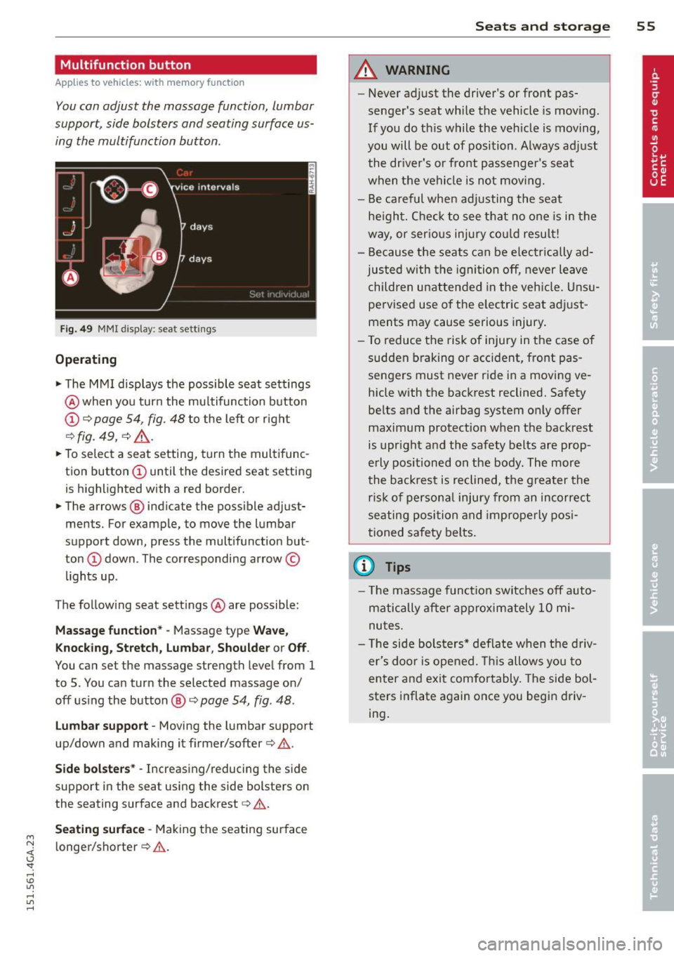
Multifunction button
Applies to vehicles: with memory function
You con adjust the massage function, Lumbar
support, side bolsters and seating surface us
ing the multifunction button .
Fig. 49 MMI display: seat sett ings
Operating
.. The MMI displays the possible seat settings
@ when you turn the mu ltifunction button
(D c:> page 54, fig. 48 to the left or right
~ fig . 49 , c:> ,& .
.. To select a seat setting, turn the multifunc
tion button
(D until the desired seat setting
is highlighted with a red border.
• The arrows @ indicate the possible adjust
ments. For example, to move the lumbar
support down, press the multifunction but
ton
(D down . The corresponding arrow ©
lights up .
T he follow ing seat settings @ are possible:
Massag e fun ct ion * -Massage type Wave,
Kn ock ing, S tretch, Lumb ar, Sho ulde r or Off.
You can set the massage strength level from 1
to 5. You can turn the selected massage on/
off us ing the button @~
page 54, fig . 48 .
Lu mba r support -Moving the lumbar support
up/down and making it firmer/softer
c:> .&. .
Side bol sters* -Increasing/reducing the side
support in the seat using the side bolsters on
the seating surface and backrest
c:> A.
Se ati ng surfac e -Making the seating surface
l onger/shorter
c:> .&. .
Sea ts a nd s to rage 55
A WARNING
-Never adjust the driver's or front pas
senger's seat while the vehicle is moving.
If you do th is while the veh icle is moving,
you will be out of position . A lways adjust
the dr iver's or front passenger's seat
when the vehicle is not moving.
- Be careful when adjusting the seat
he ight. Check to see that no one is in the
way, or ser ious injury cou ld resu lt!
- Because the seats can be electrically ad
justed with the igni tion off, never leave
children unattended in the veh icle. Unsu
pervised use o f the electric seat adjust
ments may cause serious injury.
- To reduce the risk of injury in the case of
sudden braking or accident, front pas
sengers must never ride in a moving ve
hicle with the backrest reclined. Safety
belts and the airbag system only offer
maximum protection when the backrest
is upr ight and the safety belts are prop
erly positioned on the body . The more
the backrest is reclined, the greater the
ris k of persona l inju ry from an incorrect
seating position and improperly posi
tioned safety belts.
(D Tips
- T he massage funct ion switches off auto
matically after approximately 10 mi
nutes.
- T he side bolsters* deflate when the driv
er's doo r is opened. This allows you to
enter and exit comfortably. The side bol
sters inflate again once you begin driv
ing.
Page 74 of 316
7 2 Warm and cold
Four-zone automatic climate control
Operation
Applies to vehicles: with four -zone automa tic clima te control
We recommend pressing the IAUTO I button and setting the temperature to 72 °F (22 °C).
00 ~
"' 0
0 ..,.
"'
-- I -·1 1 -! - - -
'i ~ ~-~ AU.O ;
~• J;a:=IIT 11
---:::
___ -=-..-.. /"'-• --
SYNC ~ .jA __,
-----
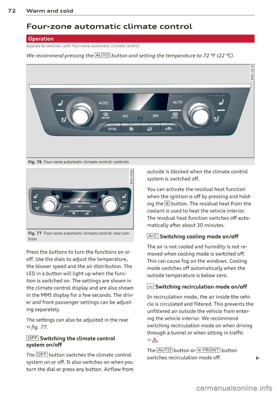
Fig. 76 Four -zone automat ic climate control: controls
Fig. 77 Four -zone automatic climate control: rear con
trols
Press the buttons to turn the functions on or
off. Use the dials to adjust the temperature,
the blower speed and the air distribution. The LED in a button will light up when the func
tion is switched on. The settings are shown in
the climate control display and are also shown
in the MMI display for a few seconds . The driv
er and front passenger sett ings can be adjust
ing separately.
The settings can also be adjusted in the rear
¢fig. 77.
IOFFj Switching the climate control
system on/off
The I O FFI button switches the climate control
system on or off.
It also switches on when you
turn the dia l or press any button. Airflow from outside is blocked when the
climate control
system is switched off .
You can activate the residual heat function
whe n the ignition is off by pressing and hold
ing the ~ button. The residua l heat from the
coolant is used to heat the vehicle interior.
The resid ual heat function switches off auto
matically after about 30 minutes.
jA/Cj Switching cooling mode on/off
T he air is not coo led and humidity is not re
moved when cooling mode is switched off.
T his can cause fog on the windows. Cooling
mode switches off automatically when the
outside temperature is be low zero.
1- 1 Switching recirculation mode on/off
In recircu lation mode, the air inside the vehi
cle is circu lated and filtered. This prevents the
unfiltered air outside the vehicle from enter
ing the vehicle interior. We recommend
switching recirculation mode on when driving
through a tunnel or when sitting in traffic
¢ .&, .
The !AUTO I button or l
Page 80 of 316

78 On the road
compartment is additionally heated by
the sun's rays.
(D Note
Do not stop the engine immediate ly after
hard or extended driving. Keep the engine r un ning for approximately two minutes to
prevent excessive heat build -up.
Driver message in the instrument
cluster display
Turn off ignition before leaving car
This message appears and a warning tone
sounds if you open the dr iver 's door when the
i gnit ion is switched on .
Press brake pedal to start engine
This message appears if you press the
I START ENGINE STOP! button to start the en
gine and do not depress the brake peda l. The
engine can on ly be started if the brake pedal
is depressed.
Ill Is key in the vehicle?
If the indicator light turns on and the mes
sage appears, the remote control key was re
moved from the vehicle while the engine was
running . If the ignition key is not in the vehi
cle you will not be ab le to switch on the igni
tion or restart the engine after it has been
switched off. You w ill also not be able to lock
the vehicle from the outside .
Shift to P, otherwise vehicle can roll away.
Doors do not lock if lever is not in P.
This message appears for sa fe ty reasons
a long with an audib le warning tone if the P
selector lever position is not engaged when
stopping the engine with the
I STAR T ENGIN E ST OP ! button . Select the P se
lector lever position . Otherwise the vehicle
could roll and it can not be locked .
II Key is not recognized. Hold back of key
against marked area . See owner's manual.
If the indicator light turns on and this mes
sage appears, there is a malfunction
¢ page 78.
Turn off ignition before leaving car. Battery
is discharging
T h is message appears if the driver's door is
opened while the ignition is switched on. Al
ways switch off the ignit ion if you are leav ing
the vehicle . See also
¢ page 82.
Shift to P and turn off ignition before leav
ing car, otherwise vehicle can roll away
This message appears if the driver's door is
opened wh ile the ignition is switched on and
the selec tor lever is not in the P position. Shift
the selec tor lever into the P position and
swi tch off the ignition when you exit the vehi
cle. Otherwise the vehicle could roll . See also
¢ page 82.
Starting the engine if there is a
malfunction
It may not be possible to start the engine un
der cer tain circums tances, for example if the
ba ttery in the vehicle key is drained, if in ter
ference hos affected the key or if there is a
system malfunction .
Fig. 82 Center co nsol e/master key: star ting the eng ine
i f the re is a mal funct ion
Requirement: The message Key not recog
nized. Hold back of key against marked area.
See owner's manual.
must appear and the in
dicator light
II must sw itch on .
.,. Hold the master key vertically in the loca
tion indicated
f >l) ¢ fig . 82 .
.,. Press the brake pedal ¢ A in Starting the
engine on page
77 .