check AUDI A7 2018 Repair Manual
[x] Cancel search | Manufacturer: AUDI, Model Year: 2018, Model line: A7, Model: AUDI A7 2018Pages: 274, PDF Size: 42.77 MB
Page 239 of 274
a co ,...,
N
" N ,...,
0 00 <..:l '
s u sp .: jack mode > Off .
The vehicle jack mode* swi tches off automatical
l y at speeds above 6 mph ( 10 km/h).
_& WARNING
Always read and follow all WARNINGS and in
formation
c:> ,1,. in Raising the vehicle on
page 239
and c:> page 241.
After changing a wheel
A wheel change is not complete without the do
ing the following.
.,. Always store the vehicle tool kit, the jack* and
the replaced tire in the luggage compartment
c:> page 134.
... Check the tire p re ssu re on the spare wheel im
mediately after mounting it.
... As soon as possible, have the tighten ing tor
que s
on all wheel bolts checked with a torque
wrench. The correct tightening torque is 90 ft
lbs (120 Nm).
.,. Have the flat tire replaced as soon as possib le.
@ Tips
- If you notice t hat the wheel bolts are cor
roded and diffic ult to turn wh ile changing a
tire, they should be rep laced before yo u
chec k the tightening torque.
- Drive at reduced speed until you have the
tightening torques chec ked.
- After changing a wheel, the tire pressure in
all four tires must be checked/corrected and
the tire pressure mon itor ing indicator must
be stored in the MM I
c:> page 224,
c:> page 226 .
Emergen cy as sis tanc e
Decorative wheel covers
Applies to: vehicles with decorative wheel covers
The decorative wheel covers must be removed
first to access the wheel bolts.
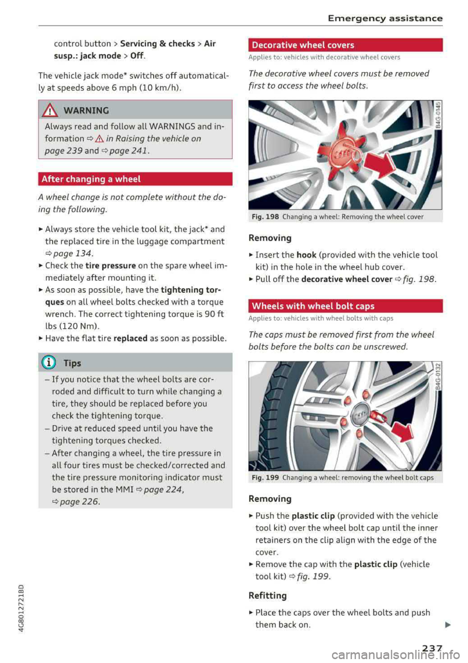
F ig. 1 98 Changing a wheel: Removing the whee l cover
Removing
... Insert the hoo k (provided w ith the vehicle tool
kit) in the hole in the wheel hub cover.
... Pull off the decorati ve w heel co ve r c:> fig. 198 .
Wheels with wheel bolt caps
Applies to: vehicles with wheel bolts with caps
The caps must be removed first from the wheel
bolts before the bolts can be unscrewed.
Fi g. 199 Cha ng ing a whee l: remov ing the wheel bolt caps
Removing
.,. Push the pla st ic clip (prov ided with the vehicle
too l kit) over the wheel bolt cap until the inner
reta iners on the clip al ign with the edge of the
cover.
... Remove the cap with the pla stic clip (vehicle
too l kit)
c:>fig. 199.
Refitting
.,. Place the caps over the whee l bolts and push
them back on.
2 37
Page 242 of 274

Emergency assistance
Taking the wheel off/installing the spare
Follow these instructions step-by-step for chang
ing the wheel .
Fig. 204 Changing a wheel: using the screw driver handl e
(wit h th e blade re m oved) to turn the bol ts
F ig . 205 Changing a wheel: alignment p in inside t he top
hole
Afte r you have loosened a ll w heel bo lts and
raised t he vehi cle off the ground, remove and re
p lace the whee l as fo llows:
Removing the wheel
• U se the hexagonal so cket in the screwdriver
handle
t o comple tely remove the topmost
whee l bolt and set it aside on a
clean surfa ce
¢ fig. 204 .
• Screw the th readed end of the alignment pin
from the tool kit hand-tight into the empty bolt
hole¢ fig. 2051> .
• Then remove the other wheel bolts as described
above.
• Takeoff th e wheel leav ing the a lignment pin in
the bo lt ho le
¢ 0 .
l) Applies to vehicles with ceram ic brake rotors*: Use a sec
ond alignment
pin* (stored in th e spa re whee l well mo ld
ing) for the lower ho le, fo llowing t he descr iption for the
first alignment pin .
240
Putting on the spare wheel
• Lif t the sp are whee l and caref ully slide it over
t he alignment p in to guide it in place
¢ (D .
• Use the hexagonal socket in the sc rewdr iver
ha nd le to screw in and tighten a ll w heel bolts
slightly.
• Remove the alignment pin and insert and t ight
en the remaining w heel bo lt slight ly like the
rest.
• Tu rn the jack hand le co unte r-clockw ise to lowe r
t he vehicle unt il t he jac k is f ully re leased.
• Use the w heel bo lt wren ch to tighten a ll wheel
bolts fi rm ly¢
p age 238. Tighten them cross
wise,
from one bo lt to the (a pprox imately) op
posite one, to keep the whee l centered.
([» Note
When remov ing o r installin g the wheel, the
rim co uld hit the brake rotor/ce ramic brake
r otor * and damage t he rotor . Work carefully
and have a second person he lp you.
(D Tips
N eve r use the he xagonal socket in the han dle
of the sc rew drive r to loosen or t ig hten the
whee l bolts.
- Pull the reversible blade from the screwdr iv
er before yo u use t he hexagona l soc ket in
t h e handle to t urn the whee l bolts.
- When mounti ng tires with
unidirectional
tread design
make sure the tread pattern is
pointed the right
way¢ page 241.
- The wheel bolts sho uld be clean and easy to
t u rn. Check fo r dirt and corrosion on the
mating surfaces of both the wheel and t he
hub. Remove all d irt from these s urfaces be
fore remounti ng the whee l.
Page 243 of 274

a co ,...,
N
" N ,...,
0 00 <.,;) '
Tires with unidirectional tread design must be
mounted with their tread pattern pointed in the
right direction .
Using a spare tire with a tread pattern
intended for use in a specific direction
When using a spare t ire with a tread pattern in
tended fo r use in a specific direction, please note
the following:
- The direction of rotat ion is marked by an arrow
on the side of the tire .
- If the spare tire has to be installed in the incor
rect direction, use the spare tire only tempora
rily s ince the tire will not be able to achieve its
opt imum performance character istics with re
gard to aquaplaning, noise and wear.
- We recommend that you pay particular atten
t ion to this fact during wet weather and that
you adjust your speed to match road condi
tions.
- Replace the flat tire with a new one and have it
installed on your vehicle as soon as possible to
restore the handling advantages of a unidirec
tiona l tire .
Notes on wheel changing
Please read the information ~ page 212, New
tires or wheels
if you are going to use a spare tire
which is different from the tires on your vehicle.
After you change a tire:
- Check the tire pressure on the spare tire im
mediately after installation.
- Have the wheel bolt tightening torque
checked with a torque wrench as soon as pos
sible by your authorized Audi dealer or a
qualified service station.
- With steel and alloy wheel rims, the wheel
bolts are correctly tightened at a torque of 90
ft lbs (120 Nm).
- If you notice that the wheel bolts are corroded
and difficult to turn while changing a tire ,
they should be replaced before you check the
tightening torque.
Emergency assistance
- Replace the flat tire with a new one and have
it installed on your vehicle as soon as possi
ble. Remount the wheel cover.
Until then , drive with extra care and at reduced
speeds.
A WARNING
- If you are going to equip your vehicle with
tires or rims which differ from those which
were factory installed, then be sure to read the information
r=> page 212, New tires or
wheels.
- Always make sure the damaged wheel or
even a flat tire and the jack and tool kit are
properly secured in the luggage compart
ment and are not loose in the passenger
compa rtment.
- In an accident or sudden maneuver they
could fly forward, injuring anyone in the ve
h icl e.
- Always store damaged wheel, jack and tools
securely in the luggage compartment. Oth
erwise, in an accident or sudden maneuver
they could fly forward, causing injury to pas
sengers in the vehicle .
Spare tire
Space-saving spare tire
App lies to : vehicles wit h spare tire
Fig. 206 Luggage compartment: space-sav ing spare tire
The spare tire is intended for short-term use on-
-
ly. Have the damaged tire checked and, if neces
sary, replaced by an authorized Audi dealer or au
thorized Audi Serv ice Facility as soon as possible .
..,.
241
Page 244 of 274
Emerg enc y assis tance
There are some restrictions on the use of the
spare tire. The spare tire has been designed spe
cifically for your type of vehicle. Do not replace it
with the spare tire from another type of vehicle.
S pac e-s av ing sp are tir e*
The tire pressure must be 61 PSI (4.2 bar).
Remov ing th e spar e tire
.,. Fold the cargo floor up to the rear bench seat .
.,. Turn the handwheel counter-clockw ise and re-
move it .
.,. Remove the spare t ire.
Snow chains
Using snow chains on the spare tire is not perm it
ted due to technical reasons .
If you have to drive with snow chains and a front
tire fa ils, mount the spare t ire in place of a rear
tire . Install the snow cha ins on the rear tire that
you removed, and install that in place of the
front tire that failed.
A WARNING
-
- After installing a spa re t ire, the tire p res
s u re must be checked as quickly as poss ible.
- Do not drive faster than SO mph (80 km/h)
with a spare tire. Driv ing faster than that in
creases the risk of an a ccident.
- Avoid full-throttle accelerat ion, heavy b rak
ing, and fast cornering, because this in
creases the risk of an accident.
- Never dr ive using more than one spa re t ire,
because th is increases the r isk of an acci
dent.
- Norma l tires o r winter tires m ust not be
mounted on the spare tire rim .
- Only use the co llapsible spare tire in emer
gencies and dr ive very carefu lly, especially if
it is more than 6 years o ld .
242
Page 245 of 274
a co ,...,
N
" N ,...,
0 00 <..:l '
Replacing fuses
A fuse that has blown will have metal strips that have burned through.
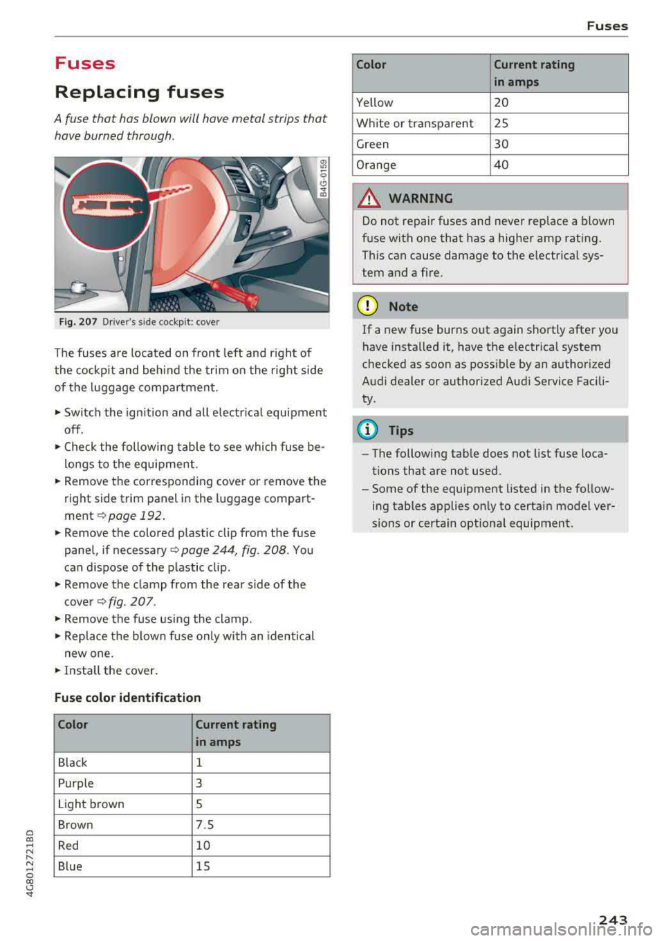
Fig. 207 Driver's s ide cockpit : cover
The fuses are located on front left and r ight of
the cockpit and behind the trim on the right side
of the luggage compartment.
• Switch the ignition and all electrica l equipment
off .
• Check the following table to see which fuse be
longs to the equipment.
• Remove the corresponding cover or remove the
right side trim panel in the luggage compart
ment
¢ page 192.
• Remove the colored plastic clip from the fuse
panel, if
necessary¢ page 244, fig. 208. You
can dispose of the plastic clip.
• Remove the clamp from the rear s ide of the
cover
Q fig . 207.
• Remove the fuse using the clamp.
• Replace the blown fuse only with an identical
new one.
• Install the cover.
Fuse color identification
Color Current rating
in amps
Black 1
Purple 3
Light brown 5
Brown 7.5
Red 10
Blue 15
Fuses
Color Current rating
in amps
Yellow 20
White or transparent 25
Green 30
Orange 40
A WARNING
Do not repair fuses and never replace a blown
fuse with one that has a higher amp rating.
This can cause damage to the electrical sys
tem and a fire.
(D Note
If a new fuse burns out again shortly after you
have installed it, have the electrical system
checked as soon as poss ible by an authorized
Audi dealer or authorized Audi Service Facili
ty.
(D Tips
- The following table does not list fuse loca
tions that are not used.
- Some of the equipment listed in the follow
ing tables applies only to certain model ver
sions or certa in optional equipment.
243
Page 249 of 274

a co .... N
" N .... 0 00 \.J '
General
This chapter is intended for trained emergency
crews and working personnel who have the nec
essary tools and equipment to perform these
operations.
Starting by pushing or
towing
~ Note
Vehicles with an automatic transmission can
not be started by pushing or towing.
Starting with jumper
cables
If necessary, the engine can be started by con
necting it to the battery of another vehicle .
If the engine should fail to start because of a dis
charged or weak battery, the battery can be con
nected to the battery of
another vehicle, using a
pair of jumper cables to start the engine.
Jumper cables
Use only jumper cables of sufficiently large cross
section
to carry the starter current safely. Refer
to the manufacturer's specifications.
Use only jumper cables with
insulated terminal
clamps which are distinctly marked :
plus(+) cable in most cases colored red
minus(-) cable
in most cases colored black.
A WARNING -
Batteries contain electricity, acid, and gas.
Any of these can cause very serious or fatal in
jury. Follow the instructions below for safe
handling of your vehicle's battery .
-Always shield your eyes and avoid leaning
over the battery whenever possible.
-A dead battery can freeze at temperatures
around 32 °F (0 °C) . If the vehicle battery is
frozen, you must thaw it before connecting
the jump start cables. If you do not, this in-
Emergency situations
creases the risk of an explosion and chemi
cal burns. After jump starting the vehicle,
drive to an authorized Audi dealer or author ized Audi Service Facility immediately to
have the vehicle battery checked.
- Do not allow battery acid to contact eyes or
skin . Flush any contacted area with water
immediately.
- Improper use of a booster battery to start a
vehicle may cause an explosion .
- Vehicle batteries generate explosive gases .
Keep sparks, flame and lighted cigarettes
away from batteries.
- Do not try to jump start any vehicle with a
low acid level in the battery .
- The voltage of the booster battery must also
have a 12-volt rating . The capacity (Ah) of
the booster battery should not be lower
than that of the discharged battery. Use of
batteries of different voltage or substantial
ly different "Ah " rating may cause an explo
sion and personal injury.
- Never charge a frozen battery. Gas trapped
in the ice may cause an explosion.
- Never charge or use a battery that has been
frozen. The battery case may have be weak
ened.
- Use of batteries of different voltage or sub
stantially different capacity (Ah) rating may
cause an explosion and injury. The capacity
(Ah) of the booster battery should not be
lower than that of the discharged battery.
- Before you check anything in the engine
compartment, always read and heed all
WARNINGS
c>page 193.
@ Note
- Applying a higher voltage booster battery
will cause expensive damage to sensitive
electronic components, such as control
units, relays, radio, etc.
- There must be no electrical contact between
the vehicles as otherwise current could al
ready start to flow as soon as the positive
( + ) terminals are connected.
247
Page 251 of 274
-Be fore yo u chec k any thing in the engine
compartment, a lways read and heed a ll
WARNINGS
c:::> page 193 .
(D Note
Impro per hook-u p of jum per cables c an r uin
the gene rato r.
-Always connect P OSITIVE( +) to POS ITIV E
( + ), and NEG ATIVE( -) to NEGATI VE( -)
g round post of t he battery manage r contro l
unit.
- Check that a ll sc rew p lugs on t he battery
ce lls are screwed in f irmly . If not, t ighten
plugs p rior to connecting clamp on negative
b attery termi nal.
- Please note t hat the procedure fo r con nect
i ng a jumper cab le as desc ribed above ap
pli es specifica lly to the case of yo ur vehicle
b eing jump starte d. W hen you are giv ing a
ju mp s ta rt to ano ther vehicle , d o
no t con
ne ct t he negative( -) cable to the neg ative
(-) t ermin al on the disch arged b attery @
c:::> fig . 212 . In stead , securely connec t the
n egative ( -) cable to either a solid metal
com ponent that is firm ly bolted to the e n
gine block or to the engine bloc k itsel f. If
the battery that is be ing charged does not
vent to the outs ide, escap ing battery gas
could ignite and ex plode!
Towing with a tow truck
General hints
Your Audi requires special handling for towing .
The follow ing informa tion is to be used by com
mercia l tow tr uck operators who know how to op
e rate the ir equip men t sa fely.
- Never tow your Audi. Towing will cause dam
age to the engine and transmission .
- Never wrap the safety chains or winch cables
around the brake line s.
- To prevent unnecessary damage, your Audi
must be transported with a flatbed tru ck .
a co -To load the vehicle on to the flatbed , use the ,...,
~ towing loop found in the vehicle tools and at-N ,...,
0 00 <.,;) '
tach to the front or rear anchorage
c:::> pag e 249 and c:::>page 250 .
A WARNING
-
A veh icle bei ng towed is not safe for passen-
gers . N ever allow anyone to ride in a vehicle
being towed, for any reason.
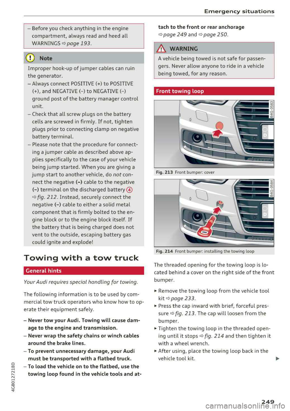
Front towing loop
Fig. 213 Front bu mpe r: co ve r
Fig. 214 Front bu mper: i nst all ing the tow ing loop
T he t hreaded o pen ing for th e towing loop is lo
cated be hind a cover on the r ight side of the front
bumper .
.,. Remove the towing loo p from the vehi cle too l
k it
c:::> page 2 3 3 .
.,. Press the cap inward with brief, force ful p res
su re
c:::> fig. 213 . The cap will loosen from the
bumper.
.,. T ighten the towing loop in the threaded open
ing until it sto ps
c:::> fig . 214 and then tighten it
w ith a wheel w re nch .
.,. After usi ng, p lace the tow ing loop back i n the
veh icle tool kit.
..,.
249
Page 252 of 274
Emergency situations
& WARNING
If the towing loop is not tightened until it
stops when installing, the threads may be
pulled out when towing the vehicle and that
could cause an accident.
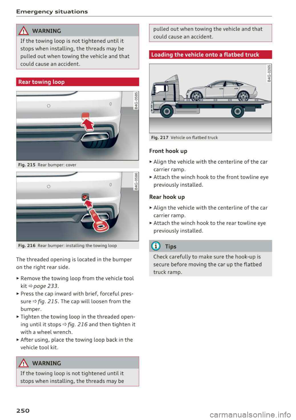
Rear towing loop
0 0
F
ig. 215 Rear bumper : cover
0 0
F
ig. 216 Rear bumper : installi ng the towing loop
The threaded opening is located in the bumper
on the right rear side .
.. Remove the towing loop from the vehicle tool
kit
o page 233 .
.. Press the cap inward with brief, forceful pres
sure
o fig . 215 . The cap will loosen from the
bumper .
.. Tighten the towing loop in the threaded open
ing until it stops
<=?fig. 216 and then tighten it
with a whee l wrench .
.. After using, place the towing loop back in the
vehicle tool kit.
A WARNING
If the towing loop is not tightened until it
stops when installing, the threads may be
250
-
pulled out when towing the vehicle and that
could cause an accident .
Loading the vehicle onto a flatbed truck
Fig. 217 Vehicle on f latbed truck
Front hook up
l8 N 0
CJ .., m
.. Align the vehicle with the centerline of the car
carrier ramp .
.. Attach the winch hook to the front towline eye
previously installed.
Rear hook up
.. Align the vehicle wi th the centerl ine of the car
carrier ramp .
.. Attach the winch hook to the rear towline eye
previously installed.
@ Tips
Check carefully to make sure the hook-up is
secure before moving the car up the flatbed
truck ramp .
Page 253 of 274
a co ,...,
N
" N ,...,
0 00 <.,;) '
Lifting with workshop hoist and with floor
jack
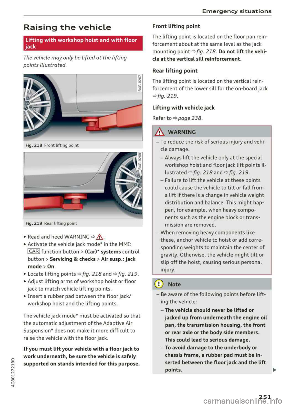
The vehicle may only be lift ed at the lifting
points illus tr at ed.
Fig. 218 Fro nt lift in g poin t
Fig. 219 Re ar lift ing poin t
.,. Read and heed WARNING c::> &, .
.. Activate the veh icle ja ck mode* in the M MI:
I CAR I funct ion button> (Car) * systems contro l
bu tton >
Servicing & checks > Air susp.: jack
mode > On .
.. Loca te lift ing po ints c::> fig . 218 and c::>fig . 219 .
.. Adju st lifting arms of wo rkshop hoist o r floo r
jack t o match vehicle li fting poin ts.
.. In se rt a rubb er pa d between the floor jack/
wor kshop ho ist a nd the lifting points .
T he vehicle ja ck m ode* mus t be activa ted so that
the au tomatic a djustment of the Ad aptive Air
Suspension * does no t make it more difficult to
raise the ve hicle wit h the floor jac k.
If you must lift your vehicle with a floor jack to
work underneath, be sure the vehicle is safely
supported on stands intended for this purpose . Emergency situations
Front lifting point
T he lifting poin t is locate d on the floor p an rein
f o rcement about at the same level as the ja ck
mounting point
c::> fig . 218 . Do not lift the vehi
cle at the vertical sill reinforcement .
Rear lifting point
T he lifting p oin t i s lo cate d on the ve rtic al rei n
f o rceme nt o f th e lower s ill for the on- bo ar d jac k
c::>fig. 219.
Lifting with vehicle jack
Refer to c::> pag e 238 .
A WARNING
- To reduce the r is k of se rious inju ry and veh i
cle dama ge.
-Always lift the vehicle o nly at the specia l
wor kshop h oist a nd f loor jack lift points
il
l ustrated c::> fig. 218 and c::> fig. 219.
-Failure to lift t he ve hicle at these points
could cause t he veh icle to tilt o r fall from
a lift i f th ere is a change in vehicle weight
dist ribution and balance . This might hap
pen, fo r example, when heavy compo
n en ts such as the eng ine block o r trans
missi on a re removed .
- Whe n re mov ing heavy comp onents like
these, an ch or veh icle t o hois t or ad d co rre
spon ding weig hts t o m aintai n the cen ter of
g ravi ty . Ot herw ise, the vehicle mig ht tilt or
slip off t he hoist, caus ing se rio us pe rsonal
i njur y .
(D Note
-Be aw are of the fo llow ing po ints b efor e lift
ing the vehicle:
-The vehicle should never be lifted or
jacked up from underneath the engine oil
pan, the transmission housing, the front
or rear axle or the body side members.
This could lead to serious damage .
-To avoid damage to the underbody or
chassis frame, a rubber pad must be in
serted between the floor jack and the lift
points .
.,.
251
Page 254 of 274
Emergency situations
-Before driving over a workshop hoist,
check that the vehicle weight does not
exceed the permissible lifting capacity of
the hoist.
-Before driving over a workshop hoist, en
sure that there is sufficient clearance be
tween the hoist and low parts of the ve hicle.
Vehicle transport
Applies to: vehicles with air suspension
~ Note
When transporting the vehicle on a car carri
er, train , ship or by other means, only tie the
vehicle down at the running surface of the
tires, which is the outer circumference. Secur
ing the vehicle at the axle components, sus
pension struts or towing eyes is not permitted
because the pressure in the air suspension
struts can change during transport. The vehi
cle may not be secured sufficiently if this hap
pens.
252