lock AUDI A8 1996 D2 / 1.G 01V Transmission Select Lever Mechanism Workshop Manual
[x] Cancel search | Manufacturer: AUDI, Model Year: 1996, Model line: A8, Model: AUDI A8 1996 D2 / 1.GPages: 75, PDF Size: 0.76 MB
Page 1 of 75
37-1
Selector lever mechanism,
servicing
WARNING!
Shift selector lever into position "P" and
engage parking brake before working with the
engine running.
Notes:
Lubricate bearing areas and slide surfaces with
polycarbamide grease G 052 142 A2.
Center console must be removed for service
work:
Ignition key removal lock, checking
- Switch ignition key to driving position (ignition
on).
- Depress brake pedal and hold.
Shifting selector lever out of position "P"
must be possible with the button at shift lever
depressed without "sticking".
It must not be possible to remove ignition
Pa
ge 1 of 75 Selector lever mechanism, servicin
g
11/20/2002 htt
p://127.0.0.1:8080/audi/servlet/Dis
play?action=Goto&t
yp
e=re
pair&id=AUDI.B5.AT01.37.1
Page 3 of 75
37-2
Shift mechanism, checking
Selector lever in position "P" and ignition
switched on:
Brake pedal is not being operated:
Selector lever is locked and cannot be shifted
out of position "P" with the button at selector
lever pressed. Shift lock solenoid is locking the
selector lever.
Brake pedal is being operated:
Shift lock solenoid enables the selector lever.
Selecting a driving mode must be possible with
the button at shift handle pressed without
"sticking".
Slowly shift selector lever through "P" via " R, N,
D, 4, 3, 2", while checking if the selector lever
position in instrument cluster matches with the
selector lever position.
Pa
ge 3 of 75 Selector lever mechanism, servicin
g
11/20/2002 htt
p://127.0.0.1:8080/audi/servlet/Dis
play?action=Goto&t
yp
e=re
pair&id=AUDI.B5.AT01.37.1
Page 4 of 75
37-3
Selector lever in position "N" and ignition
switched on:
Brake pedal is not being operated:
Selector lever is locked and cannot be shifted
out of position "N" with the button at selector
lever handle pressed. Shift lock solenoid is
locking the selector lever.
Brake pedal is being operated:
Shift lock solenoid enables the selector lever.
Selecting a driving mode must be possible with
the button at shift handle pressed without
"sticking".
Additional test only for shift mechanisms
with Tiptronic: Selector lever in position "D",
ignition and lights switched on
Start engine and let run at idle
Engage parking brake and operate brake
pedal
Guide selector lever out of selector lever
position "D" into Tiptronic gate. Brightening of
Pa
ge 4 of 75 Selector lever mechanism, servicin
g
11/20/2002 htt
p://127.0.0.1:8080/audi/servlet/Dis
play?action=Goto&t
yp
e=re
pair&id=AUDI.B5.AT01.37.1
Page 6 of 75
37-4
Notes:
Starter must not start with selector lever in
positions "2", "3", "4", "D" and "R".
For Right Hand Drive (RHD) vehicles, it must
only be possible to start the starter with the
selector lever positions "P" and "N" with the
locking button in selector lever handle not
pressed.
For speeds exceeding 5 km/h and shifting into
selector lever position "N", the shift lock
solenoid must not engage to lock the selector
lever. Selector lever can be shifted into a
driving mode.
For speeds below 2 km/h (almost standstill) and
shifting into selector lever position "N", the shift
lock solenoid must only engage after approx. 1
second. Selector lever can only be shifted out
of position "N" with the brake pedal operated.
Pa
ge 6 of 75 Selector lever mechanism, servicin
g
11/20/2002 htt
p://127.0.0.1:8080/audi/servlet/Dis
play?action=Goto&t
yp
e=re
pair&id=AUDI.B5.AT01.37.1
Page 10 of 75
37-8
from top:
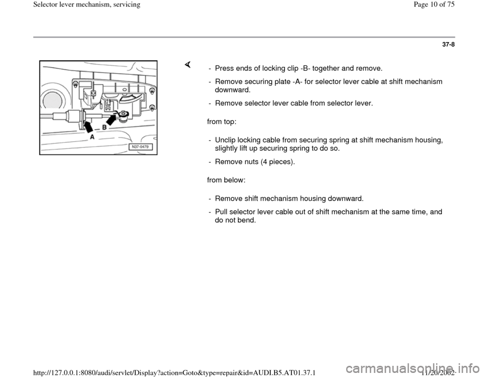
from below: - Press ends of locking clip -B- together and remove.
- Remove securing plate -A- for selector lever cable at shift mechanism
downward.
- Remove selector lever cable from selector lever.
- Unclip locking cable from securing spring at shift mechanism housing,
slightly lift up securing spring to do so.
- Remove nuts (4 pieces).
- Remove shift mechanism housing downward.
- Pull selector lever cable out of shift mechanism at the same time, and
do not bend.
Pa
ge 10 of 75 Selector lever mechanism, servicin
g
11/20/2002 htt
p://127.0.0.1:8080/audi/servlet/Dis
play?action=Goto&t
yp
e=re
pair&id=AUDI.B5.AT01.37.1
Page 11 of 75
37-9
Installing
- Installation is the reverse order of removal.
In addition, the following test steps must be
performed and observed.
Selector lever and lever/shift rod in position
"P" (park lock must engage).
- Raise vehicle.
- Guide selector lever cable into shift
mechanism.
- Do not bend selector lever cable.
- Mount shift mechanism on chassis.
- Tighten nuts (4 pieces) to 10 Nm from top.
- Secure boot of selector lever cable to shift
mechanism cover.
- Installing and adjusting locking cable page 37
-49
.
Pa
ge 11 of 75 Selector lever mechanism, servicin
g
11/20/2002 htt
p://127.0.0.1:8080/audi/servlet/Dis
play?action=Goto&t
yp
e=re
pair&id=AUDI.B5.AT01.37.1
Page 12 of 75
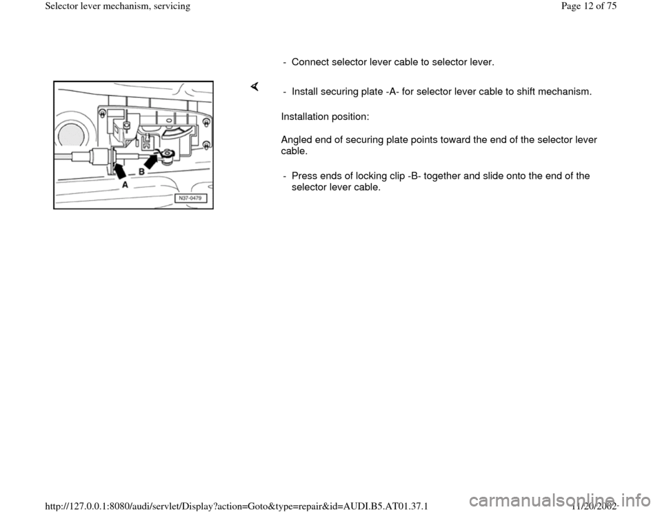
- Connect selector lever cable to selector lever.
Installation position:
Angled end of securing plate points toward the end of the selector lever
cable. - Install securing plate -A- for selector lever cable to shift mechanism.
- Press ends of locking clip -B- together and slide onto the end of the
selector lever cable.
Pa
ge 12 of 75 Selector lever mechanism, servicin
g
11/20/2002 htt
p://127.0.0.1:8080/audi/servlet/Dis
play?action=Goto&t
yp
e=re
pair&id=AUDI.B5.AT01.37.1
Page 13 of 75
37-10
- Attach cover.
All-wheel-drive vehicles
Continuation for all vehicles
Repair Manual, Engine Mechanical, Repair Group 26; removing and
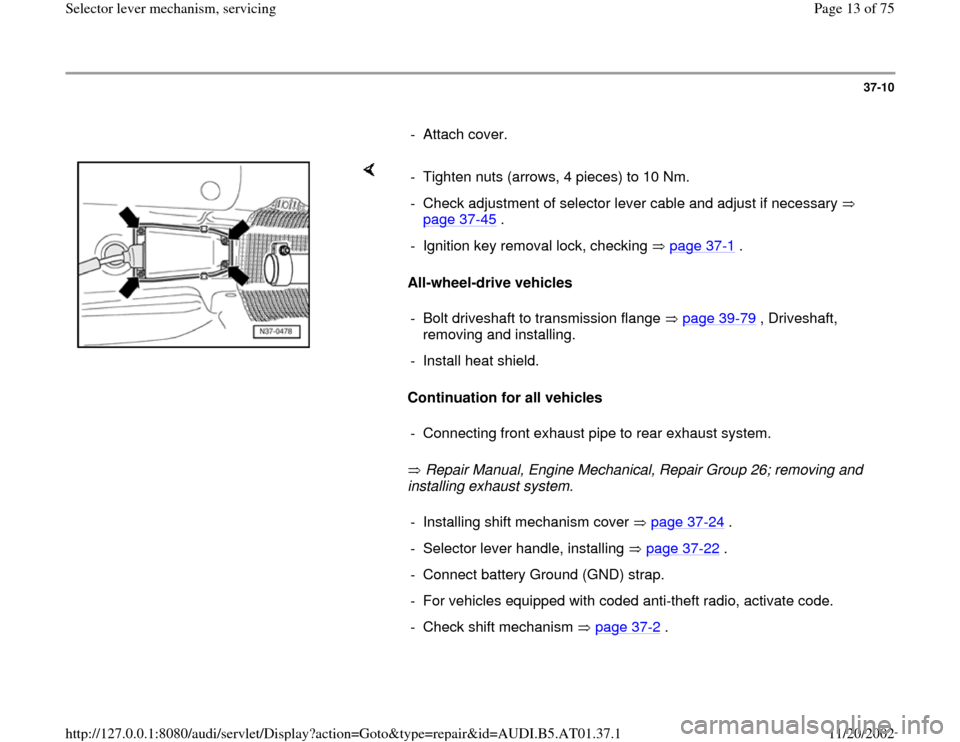
installing exhaust system. - Tighten nuts (arrows, 4 pieces) to 10 Nm.
- Check adjustment of selector lever cable and adjust if necessary
page 37
-45
.
- Ignition key removal lock, checking page 37
-1 .
- Bolt driveshaft to transmission flange page 39
-79
, Driveshaft,
removing and installing.
- Install heat shield.
- Connecting front exhaust pipe to rear exhaust system.- Installing shift mechanism cover page 37
-24
.
- Selector lever handle, installing page 37
-22
.
- Connect battery Ground (GND) strap.
- For vehicles equipped with coded anti-theft radio, activate code.
- Check shift mechanism page 37
-2 .
Pa
ge 13 of 75 Selector lever mechanism, servicin
g
11/20/2002 htt
p://127.0.0.1:8080/audi/servlet/Dis
play?action=Goto&t
yp
e=re
pair&id=AUDI.B5.AT01.37.1
Page 16 of 75
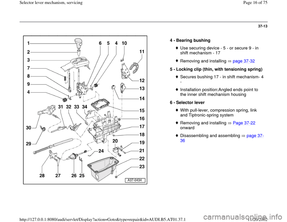
37-13
4 -
Bearing bushing
Use securing device - 5 - or secure 9 - in
shift mechanism - 17 Removing and installing page 37
-32
5 -
Locking clip (thin, with tensioning spring)
Secures bushing 17 - in shift mechanism- 4
- Installation position:Angled ends point to
the inner shift mechanism housing
6 -
Selector lever With pull-lever, compression spring, link
and Tiptronic-spring system Removing and installing Page 37
-22
onward
Disassembling and assembling page 37
-
36
Pa
ge 16 of 75 Selector lever mechanism, servicin
g
11/20/2002 htt
p://127.0.0.1:8080/audi/servlet/Dis
play?action=Goto&t
yp
e=re
pair&id=AUDI.B5.AT01.37.1
Page 17 of 75
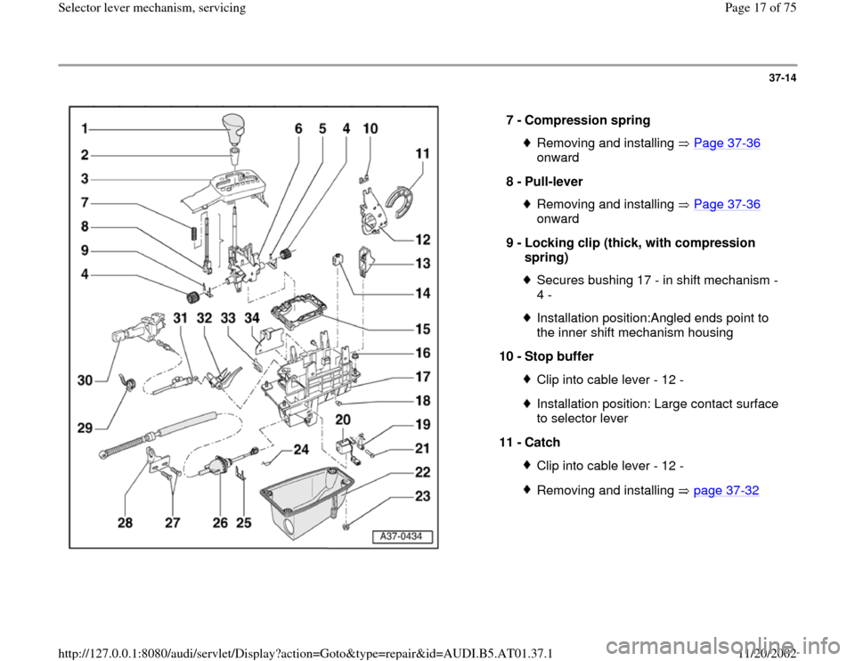
37-14
7 -
Compression spring
Removing and installing Page 37
-36
onward
8 -
Pull-lever
Removing and installing Page 37
-36
onward
9 -
Locking clip (thick, with compression
spring)
Secures bushing 17 - in shift mechanism -
4 - Installation position:Angled ends point to
the inner shift mechanism housing
10 -
Stop buffer Clip into cable lever - 12 -Installation position: Large contact surface
to selector lever
11 -
Catch Clip into cable lever - 12 -Removing and installing page 37
-32
Pa
ge 17 of 75 Selector lever mechanism, servicin
g
11/20/2002 htt
p://127.0.0.1:8080/audi/servlet/Dis
play?action=Goto&t
yp
e=re
pair&id=AUDI.B5.AT01.37.1