AUDI A8 1997 D2 / 1.G ATQ Engine Additional Signals Testing Workshop Manual
Manufacturer: AUDI, Model Year: 1997, Model line: A8, Model: AUDI A8 1997 D2 / 1.GPages: 44, PDF Size: 0.19 MB
Page 1 of 44
24-165
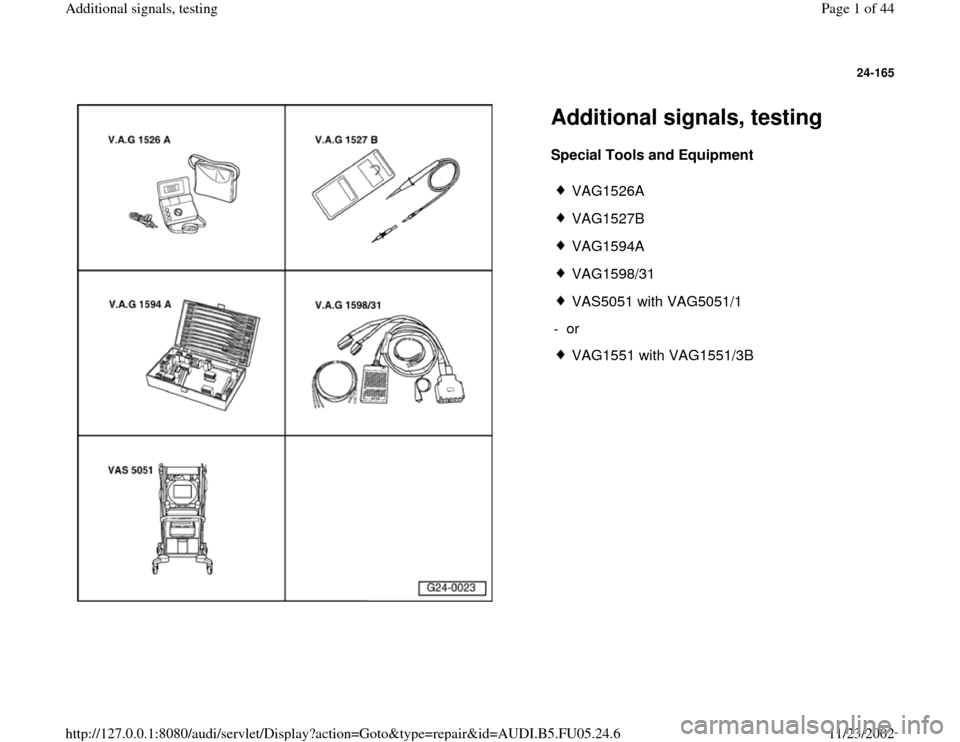
Additional signals, testing Special Tools and Equipment
VAG1526A
VAG1527B
VAG1594A
VAG1598/31
VAS5051 with VAG5051/1
- or
VAG1551 with VAG1551/3B
Pa
ge 1 of 44 Additional si
gnals, testin
g
11/23/2002 htt
p://127.0.0.1:8080/audi/servlet/Dis
play?action=Goto&t
yp
e=re
pair&id=AUDI.B5.FU05.24.6
Page 2 of 44
24-166
Engine speed signal, checking
Note:
The engine speed signal is output at terminal 37
of the Engine Control Module (ECM). The signal
is used, among other things, for RPM display in
the instrument cluster.
- Connect VAG1598/31 test box at wiring harness
to ECM, do not connect ECM Page 24
-17
.
- Check the following wire connection for open
circuit and short circuit to Ground (GND) and B+:
Test box
VAG1598/31
Socket
Instrument cluster
Terminal
37 Electrical Wiring Diagrams,
Troubleshooting & Component
Locations binder
- Repair open circuit or short circuit if
necessary.
Pa
ge 2 of 44 Additional si
gnals, testin
g
11/23/2002 htt
p://127.0.0.1:8080/audi/servlet/Dis
play?action=Goto&t
yp
e=re
pair&id=AUDI.B5.FU05.24.6
Page 3 of 44
24-167
Consumption signal for on board
computer, checking
Notes:
The consumption signal is calculated by the
ECM from the injection time and directed to the
on board computer via terminal 81 of the ECM.
Consumption signal, checking
Electrical Wiring Diagrams, Troubleshooting &
Component Locations binder
Pa
ge 3 of 44 Additional si
gnals, testin
g
11/23/2002 htt
p://127.0.0.1:8080/audi/servlet/Dis
play?action=Goto&t
yp
e=re
pair&id=AUDI.B5.FU05.24.6
Page 4 of 44
24-168
Vehicle speed signal, checking
Notes:
The vehicle speed signal is generated by the
Vehicle Speed Sensor (VSS) -G68- (at
transmission) and processed in the instrument
cluster.
The processed signal enters at terminal 54 of
the ECM and is used for idle stabilization and
tip-in shock reduction during shifting.
Test requirement:
Function and display of speedometer OK.
Troubleshooting:
Electrical Wiring Diagrams, Troubleshooting &
Component Locations binder
Pa
ge 4 of 44 Additional si
gnals, testin
g
11/23/2002 htt
p://127.0.0.1:8080/audi/servlet/Dis
play?action=Goto&t
yp
e=re
pair&id=AUDI.B5.FU05.24.6
Page 5 of 44
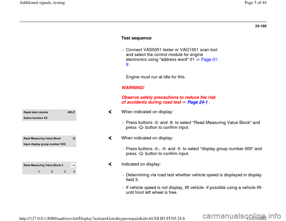
24-169
Test sequence
- Connect VAS5051 tester or VAG1551 scan tool
and select the control module for engine
electronics using "address word" 01 Page 01
-
9 .
Engine must run at idle for this.
WARNING!
Observe safety precautions to reduce the risk
of accidents during road test Page 24
-1 .
Rapid data transfer
HELP
Select function XX
When indicated on display:
- Press buttons -0- and -8- to select "Read Measuring Value Block" and
press -Q- button to confirm input.
Read Measurin
g Value Block
Q
Input displa
y group number XXX
When indicated on display:
- Press buttons -0-, -0- and -5- to select "display group number 005" and
press -Q- button to confirm input.
Read Measuring Value Block 5
1
2
3
4
Indicated on display:
- Determining via road test whether vehicle speed is displayed in display
field 3.
- If vehicle speed is not display, lift vehicle -if possible using a vehicle lift-
until front left wheel is free.
Pa
ge 5 of 44 Additional si
gnals, testin
g
11/23/2002 htt
p://127.0.0.1:8080/audi/servlet/Dis
play?action=Goto&t
yp
e=re
pair&id=AUDI.B5.FU05.24.6
Page 6 of 44
24-170
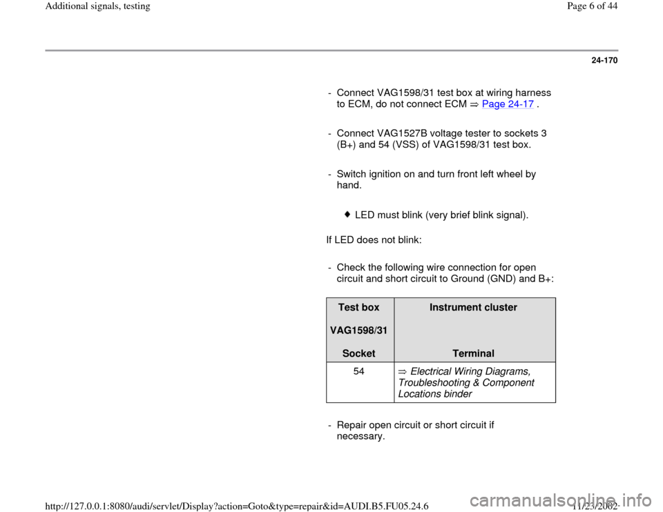
- Connect VAG1598/31 test box at wiring harness
to ECM, do not connect ECM Page 24
-17
.
- Connect VAG1527B voltage tester to sockets 3
(B+) and 54 (VSS) of VAG1598/31 test box.
- Switch ignition on and turn front left wheel by
hand.
LED must blink (very brief blink signal).
If LED does not blink:
- Check the following wire connection for open
circuit and short circuit to Ground (GND) and B+:
Test box
VAG1598/31
Socket
Instrument cluster
Terminal
54 Electrical Wiring Diagrams,
Troubleshooting & Component
Locations binder
- Repair open circuit or short circuit if
necessary.
Pa
ge 6 of 44 Additional si
gnals, testin
g
11/23/2002 htt
p://127.0.0.1:8080/audi/servlet/Dis
play?action=Goto&t
yp
e=re
pair&id=AUDI.B5.FU05.24.6
Page 7 of 44
24-171
Wire for fuel level signal, checking
Notes:
The Engine Control Module (ECM) receives the
fuel level signal from the instrument cluster.
The processed signal enters at terminal 30 of
the ECM and is used to determine the cause of
certain recognized malfunctions (e.g.
combustion misfires).
- Connect VAG1598/31 test box at wiring harness
to ECM, do not connect ECM Page 24
-17
.
- Check the following wire connection for open
circuit and short circuit to Ground (GND) and B+:
Test box
VAG1598/31
Socket
Instrument cluster
Terminal
30 Electrical Wiring Diagrams,
Troubleshooting & Component
Locations binder
- Repair open circuit or short circuit if
necessary.
Pa
ge 7 of 44 Additional si
gnals, testin
g
11/23/2002 htt
p://127.0.0.1:8080/audi/servlet/Dis
play?action=Goto&t
yp
e=re
pair&id=AUDI.B5.FU05.24.6
Page 8 of 44
24-172
A/C compressor shut-off, checking
Notes:
The A/C compressor signal communicates to
the ECM that the compressor will be switched
on in 140 ms.
The ECM can switch off the A/C compressor via
the same wire connection.
Engine Control Module (ECM) switches off A/C
compressor:
-- during hard acceleration (Wide Open
Throttle 1st gear)
-- in emergency mode (emergency
operation)
-- after initiating basic setting (function 04)
Test requirements:
A/C system OK
No DTCs in DTC memory of Engine Control
Module (ECM).
Pa
ge 8 of 44 Additional si
gnals, testin
g
11/23/2002 htt
p://127.0.0.1:8080/audi/servlet/Dis
play?action=Goto&t
yp
e=re
pair&id=AUDI.B5.FU05.24.6
Page 9 of 44
Vehicle at room temperature (warmer than
+15 C).
Pa
ge 9 of 44 Additional si
gnals, testin
g
11/23/2002 htt
p://127.0.0.1:8080/audi/servlet/Dis
play?action=Goto&t
yp
e=re
pair&id=AUDI.B5.FU05.24.6
Page 10 of 44
24-173
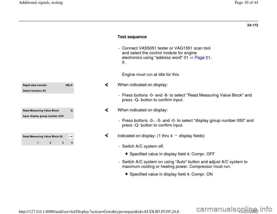
Test sequence
- Connect VAS5051 tester or VAG1551 scan tool
and select the control module for engine
electronics using "address word" 01 Page 01
-
9 .
Engine must run at idle for this.Rapid data transfer
HELP
Select function XX
When indicated on display:
- Press buttons -0- and -8- to select "Read Measuring Value Block" and
press -Q- button to confirm input.
Read Measurin
g Value Block
Q
Input display group number XXX
When indicated on display:
- Press buttons -0-, -5- and -0- to select "display group number 050" and
press -Q- button to confirm input.
Read Measuring Value Block 50
1
2
3
4
Indicated on display: (1 thru 4 display fields) - Switch A/C system off.
Specified value in display field 4: Compr. OFF
- Switch A/C system on using "Auto" button and adjust A/C system to
maximum cooling or heating power. Compressor must run.
Specified value in display field 4: Compr. ON
Pa
ge 10 of 44 Additional si
gnals, testin
g
11/23/2002 htt
p://127.0.0.1:8080/audi/servlet/Dis
play?action=Goto&t
yp
e=re
pair&id=AUDI.B5.FU05.24.6