wheel AUDI A8 1998 D2 / 1.G 01V Transmission Select Lever Mechanism Workshop Manual
[x] Cancel search | Manufacturer: AUDI, Model Year: 1998, Model line: A8, Model: AUDI A8 1998 D2 / 1.GPages: 75, PDF Size: 0.76 MB
Page 9 of 75
37-7
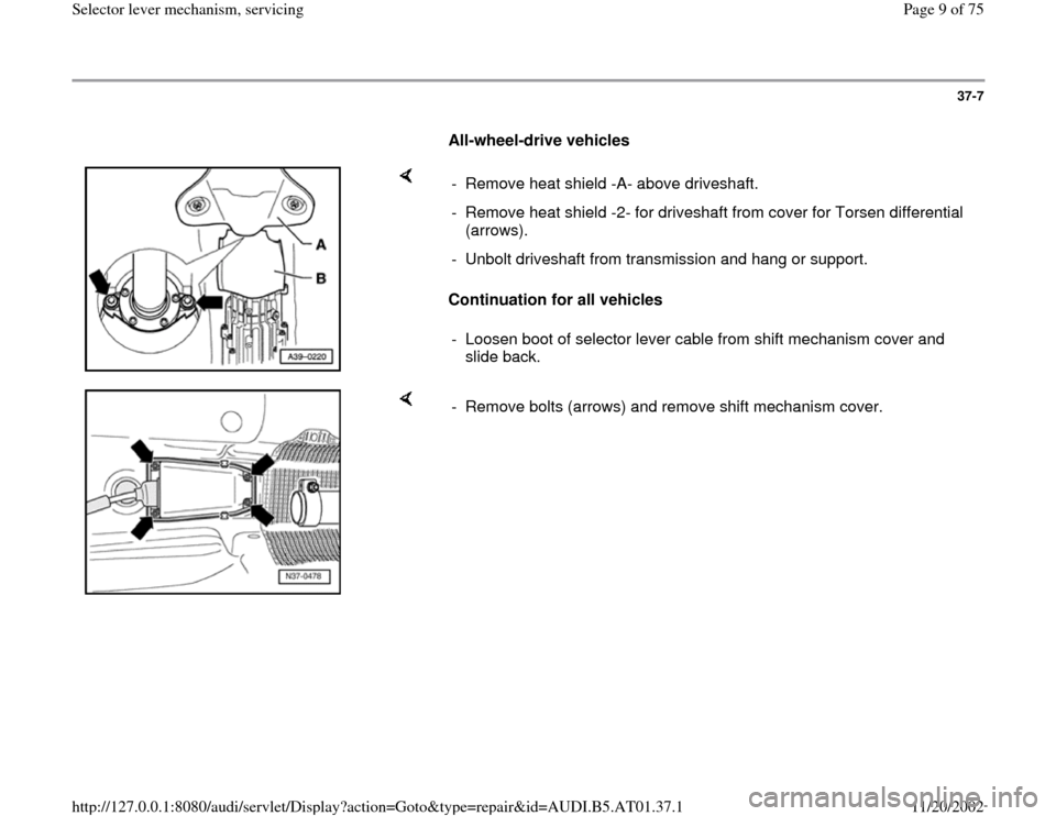
All-wheel-drive vehicles
Continuation for all vehicles - Remove heat shield -A- above driveshaft.
- Remove heat shield -2- for driveshaft from cover for Torsen differential
(arrows).
- Unbolt driveshaft from transmission and hang or support.
- Loosen boot of selector lever cable from shift mechanism cover and
slide back.
- Remove bolts (arrows) and remove shift mechanism cover.
Pa
ge 9 of 75 Selector lever mechanism, servicin
g
11/20/2002 htt
p://127.0.0.1:8080/audi/servlet/Dis
play?action=Goto&t
yp
e=re
pair&id=AUDI.B5.AT01.37.1
Page 13 of 75
37-10
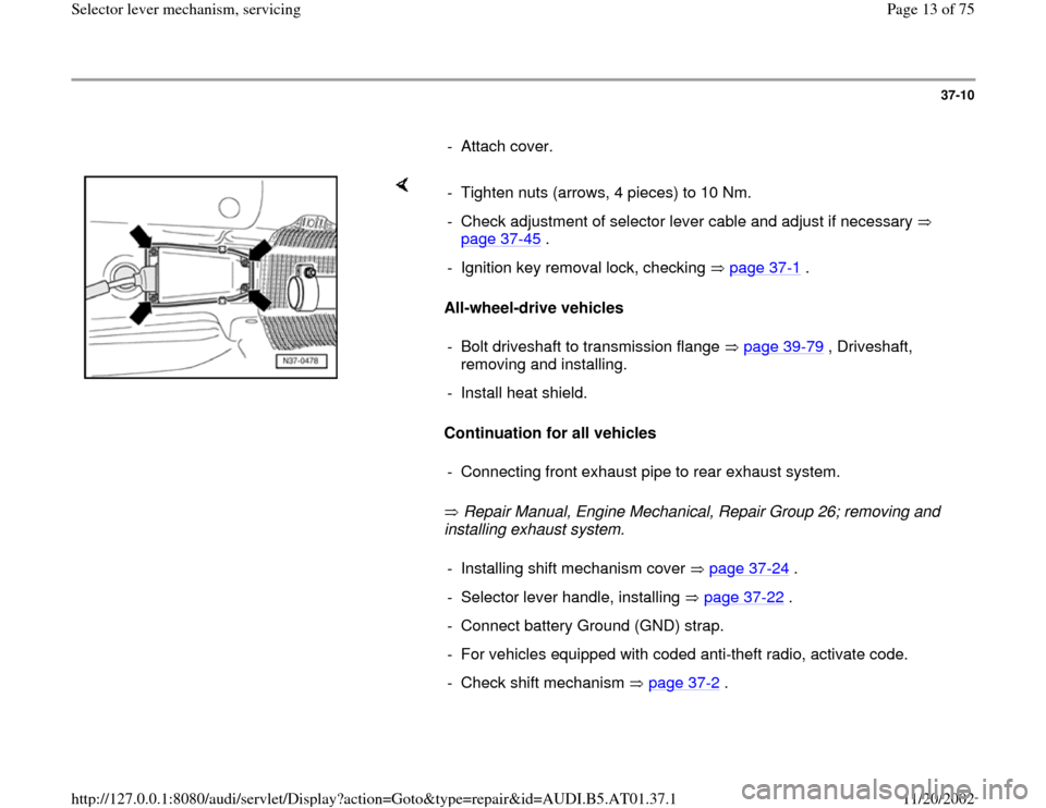
- Attach cover.
All-wheel-drive vehicles
Continuation for all vehicles
Repair Manual, Engine Mechanical, Repair Group 26; removing and
installing exhaust system. - Tighten nuts (arrows, 4 pieces) to 10 Nm.
- Check adjustment of selector lever cable and adjust if necessary
page 37
-45
.
- Ignition key removal lock, checking page 37
-1 .
- Bolt driveshaft to transmission flange page 39
-79
, Driveshaft,
removing and installing.
- Install heat shield.
- Connecting front exhaust pipe to rear exhaust system.- Installing shift mechanism cover page 37
-24
.
- Selector lever handle, installing page 37
-22
.
- Connect battery Ground (GND) strap.
- For vehicles equipped with coded anti-theft radio, activate code.
- Check shift mechanism page 37
-2 .
Pa
ge 13 of 75 Selector lever mechanism, servicin
g
11/20/2002 htt
p://127.0.0.1:8080/audi/servlet/Dis
play?action=Goto&t
yp
e=re
pair&id=AUDI.B5.AT01.37.1
Page 33 of 75
37-30
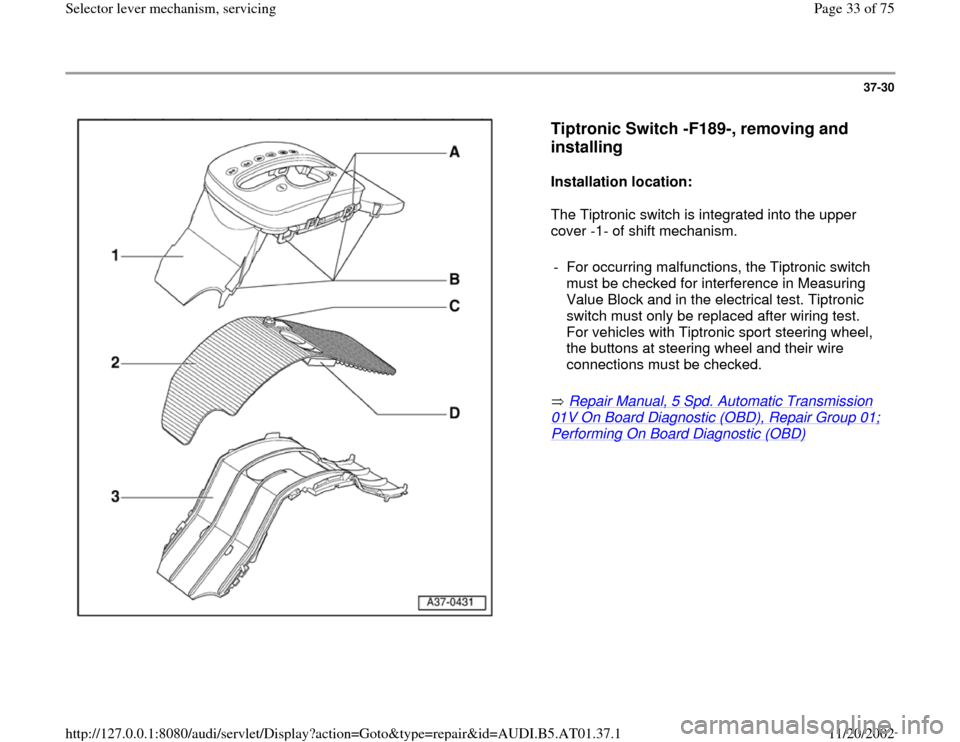
Tiptronic Switch -F189-, removing and
installing
Installation location:
The Tiptronic switch is integrated into the upper
cover -1- of shift mechanism.
Repair Manual, 5 Spd. Automatic Transmission
01V On Board Diagnostic (OBD), Repair Group 01; Performing On Board Diagnostic (OBD)
- For occurring malfunctions, the Tiptronic switch
must be checked for interference in Measuring
Value Block and in the electrical test. Tiptronic
switch must only be replaced after wiring test.
For vehicles with Tiptronic sport steering wheel,
the buttons at steering wheel and their wire
connections must be checked. Pa
ge 33 of 75 Selector lever mechanism, servicin
g
11/20/2002 htt
p://127.0.0.1:8080/audi/servlet/Dis
play?action=Goto&t
yp
e=re
pair&id=AUDI.B5.AT01.37.1
Page 46 of 75
37-41
All-wheel-drive vehicles
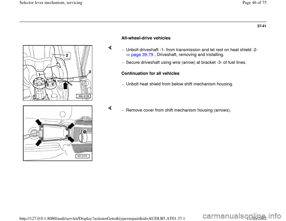
Continuation for all vehicles - Unbolt driveshaft -1- from transmission and let rest on heat shield -2-
page 39
-79
, Driveshaft, removing and installing.
- Secure driveshaft using wire (arrow) at bracket -3- of fuel lines.
- Unbolt heat shield from below shift mechanism housing.
- Remove cover from shift mechanism housing (arrows).
Pa
ge 46 of 75 Selector lever mechanism, servicin
g
11/20/2002 htt
p://127.0.0.1:8080/audi/servlet/Dis
play?action=Goto&t
yp
e=re
pair&id=AUDI.B5.AT01.37.1
Page 49 of 75
37-44
All-wheel-drive vehicles
Continuation for all vehicles
Repair Manual, Engine Mechanical, Repair Group 26, removing and
installing exhaust system.
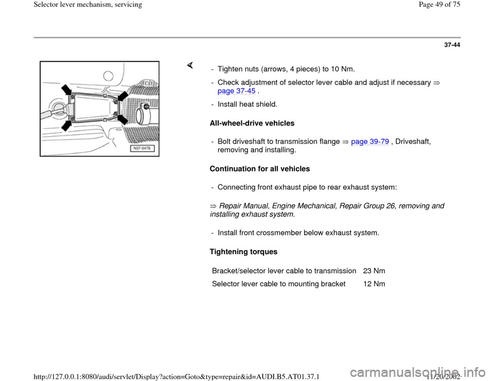
Tightening torques - Tighten nuts (arrows, 4 pieces) to 10 Nm.
- Check adjustment of selector lever cable and adjust if necessary
page 37
-45
.
- Install heat shield.
- Bolt driveshaft to transmission flange page 39
-79
, Driveshaft,
removing and installing.
- Connecting front exhaust pipe to rear exhaust system:- Install front crossmember below exhaust system.
Bracket/selector lever cable to transmission 23 Nm
Selector lever cable to mounting bracket 12 Nm
Pa
ge 49 of 75 Selector lever mechanism, servicin
g
11/20/2002 htt
p://127.0.0.1:8080/audi/servlet/Dis
play?action=Goto&t
yp
e=re
pair&id=AUDI.B5.AT01.37.1
Page 50 of 75
37-45
Selector lever cable for Tiptronic shift
mechanism, checking and adjusting
Checking
- Shift selector lever into position "P".
- Raise vehicle.
- Remove shielding plate/selector lever cable.
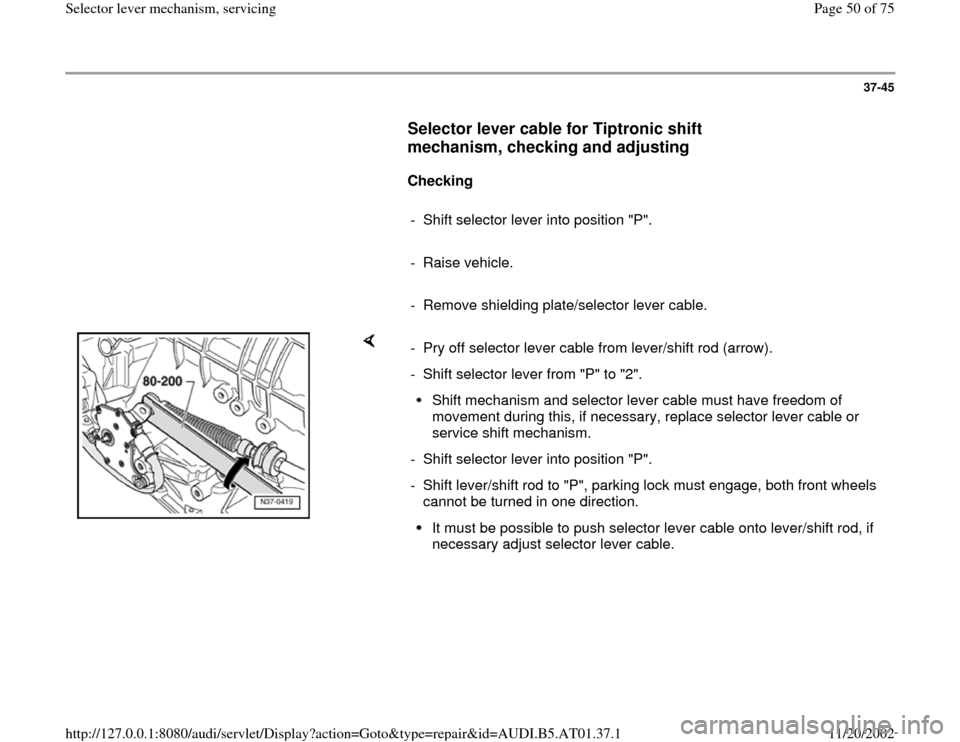
- Pry off selector lever cable from lever/shift rod (arrow).
- Shift selector lever from "P" to "2".
Shift mechanism and selector lever cable must have freedom of
movement during this, if necessary, replace selector lever cable or
service shift mechanism.
- Shift selector lever into position "P".
- Shift lever/shift rod to "P", parking lock must engage, both front wheels
cannot be turned in one direction. It must be possible to push selector lever cable onto lever/shift rod, if
necessary adjust selector lever cable.
Pa
ge 50 of 75 Selector lever mechanism, servicin
g
11/20/2002 htt
p://127.0.0.1:8080/audi/servlet/Dis
play?action=Goto&t
yp
e=re
pair&id=AUDI.B5.AT01.37.1
Page 51 of 75
37-46
Adjusting
Selector lever cable has been loosened from
lever/shift rod.
- Shift selector lever into position "P".
- Shift lever/shift rod to "P", parking lock must
engage, both front wheels cannot be turned in
one direction.
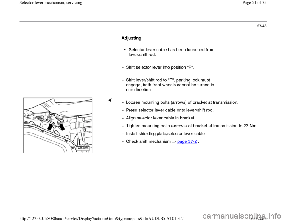
- Loosen mounting bolts (arrows) of bracket at transmission.
- Press selector lever cable onto lever/shift rod.
- Align selector lever cable in bracket.
- Tighten mounting bolts (arrows) of bracket at transmission to 23 Nm.
- Install shielding plate/selector lever cable
- Check shift mechanism page 37
-2 .
Pa
ge 51 of 75 Selector lever mechanism, servicin
g
11/20/2002 htt
p://127.0.0.1:8080/audi/servlet/Dis
play?action=Goto&t
yp
e=re
pair&id=AUDI.B5.AT01.37.1
Page 53 of 75
37-48
Repair Manual, Body Interior, Repair Group 69;
Airbag; Steering wheel, removing and installing
- Remove steering wheel.
- Switch ignition key to driving position (ignition
on).
- Shift selector lever into position "P".
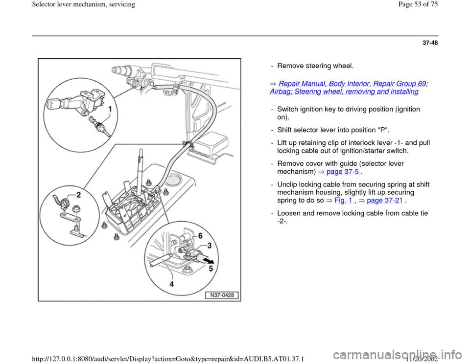
- Lift up retaining clip of interlock lever -1- and pull
locking cable out of ignition/starter switch.
- Remove cover with guide (selector lever
mechanism) page 37
-5 .
- Unclip locking cable from securing spring at shift
mechanism housing, slightly lift up securing
spring to do so Fig. 1
, page 37
-21
.
- Loosen and remove locking cable from cable tie
-2-.
Pa
ge 53 of 75 Selector lever mechanism, servicin
g
11/20/2002 htt
p://127.0.0.1:8080/audi/servlet/Dis
play?action=Goto&t
yp
e=re
pair&id=AUDI.B5.AT01.37.1
Page 56 of 75
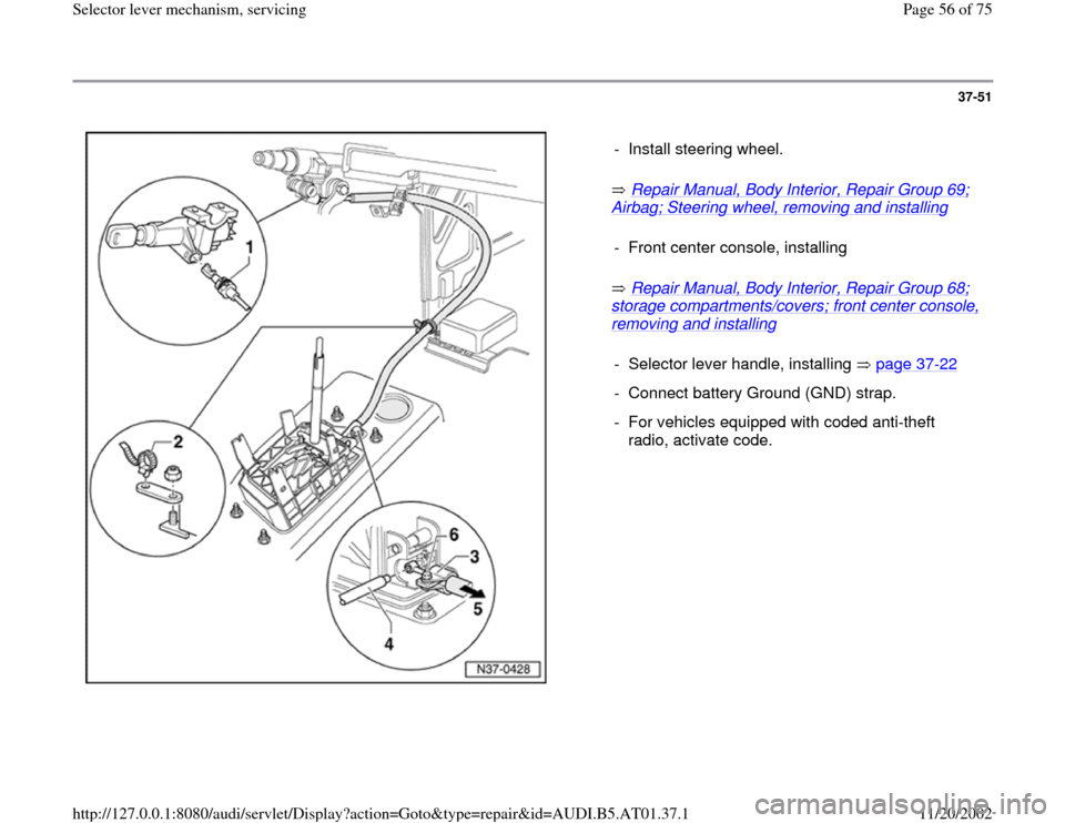
37-51
Repair Manual, Body Interior, Repair Group 69;
Airbag; Steering wheel, removing and installing
Repair Manual, Body Interior, Repair Group 68;
storage compartments/covers; front center console, removing and installing
- Install steering wheel.
- Front center console, installing- Selector lever handle, installing page 37
-22
- Connect battery Ground (GND) strap.
- For vehicles equipped with coded anti-theft
radio, activate code.
Pa
ge 56 of 75 Selector lever mechanism, servicin
g
11/20/2002 htt
p://127.0.0.1:8080/audi/servlet/Dis
play?action=Goto&t
yp
e=re
pair&id=AUDI.B5.AT01.37.1
Page 72 of 75
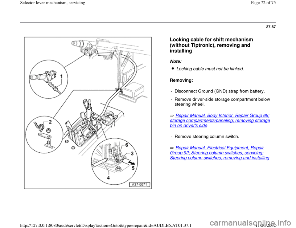
37-67
Locking cable for shift mechanism
(without Tiptronic), removing and
installing
Note:
Removing:
Repair Manual, Body Interior, Repair Group 68;
storage compartments/paneling; removing storage bin on driver's side
Repair Manual, Electrical Equipment, Repair
Group 92; Steering column switches, servicing; Steering column switches, removing and installing
Locking cable must not be kinked.
- Disconnect Ground (GND) strap from battery.
- Remove driver-side storage compartment below
steering wheel.
- Remove steering column switch.
Pa
ge 72 of 75 Selector lever mechanism, servicin
g
11/20/2002 htt
p://127.0.0.1:8080/audi/servlet/Dis
play?action=Goto&t
yp
e=re
pair&id=AUDI.B5.AT01.37.1