wiring AUDI A8 1998 D2 / 1.G AEB Engine Turbocharger Boost Control And Checking
[x] Cancel search | Manufacturer: AUDI, Model Year: 1998, Model line: A8, Model: AUDI A8 1998 D2 / 1.GPages: 17, PDF Size: 0.1 MB
Page 5 of 17
24-127
Wastegate bypass regulator valve,
checking
Function
With power off, the long connector is closed.
Both short connecters are inter-connected.
When triggered, the connection between the
long and both short connectors is opened.
Check for leaks
- Remove wastegate bypass regulator valve (
component location, page Page 24
-1 )
- Re-connect removed wastegate bypass
regulator valve to wiring harness.
- Start output Diagnostic Test Mode (DTM) and
advance through test program to select
wastegate bypass regulator valve -N75- Page
01
-42
- Blow into long connector during DTM to check
whether valve opens properly.
Pa
ge 5 of 17 Turbochar
ger boost controls, checkin
g
11/19/2002 htt
p://127.0.0.1:8080/audi/servlet/Dis
play?action=Goto&t
yp
e=re
pair&id=AUDI.B5.FU02.24.3
Page 8 of 17
24-129
Check voltage supply for wastegate bypass
regulator valve -N75-
Note:
Voltage supply for the wastegate bypass
regulator valve is provided by the fuel pump
relay.
Fuse for -N75- OK
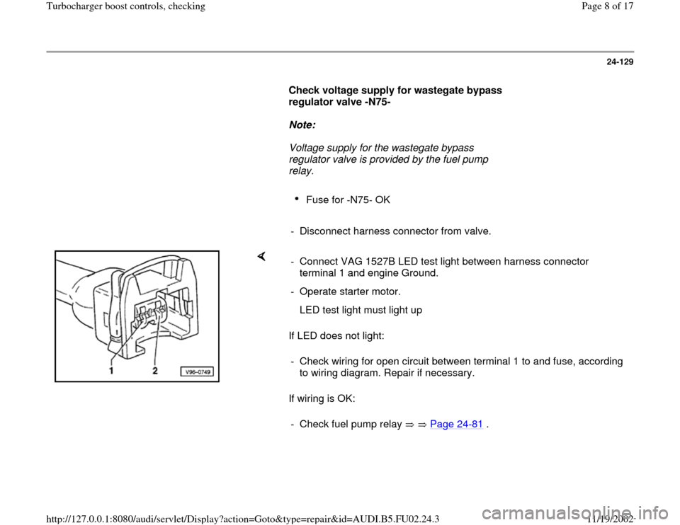
- Disconnect harness connector from valve.
If LED does not light:
If wiring is OK: - Connect VAG 1527B LED test light between harness connector
terminal 1 and engine Ground.
- Operate starter motor.
LED test light must light up
- Check wiring for open circuit between terminal 1 to and fuse, according
to wiring diagram. Repair if necessary.
- Check fuel pump relay Page 24
-81
.
Pa
ge 8 of 17 Turbochar
ger boost controls, checkin
g
11/19/2002 htt
p://127.0.0.1:8080/audi/servlet/Dis
play?action=Goto&t
yp
e=re
pair&id=AUDI.B5.FU02.24.3
Page 9 of 17
24-130
Signal for wastegate bypass regulator valve,
checking
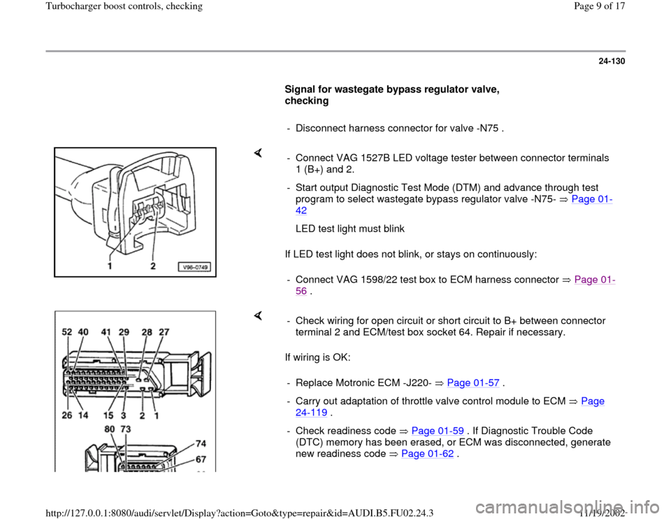
- Disconnect harness connector for valve -N75 .
If LED test light does not blink, or stays on continuously: - Connect VAG 1527B LED voltage tester between connector terminals
1 (B+) and 2.
- Start output Diagnostic Test Mode (DTM) and advance through test
program to select wastegate bypass regulator valve -N75- Page 01
-
42
LED test light must blink
- Connect VAG 1598/22 test box to ECM harness connector Page 01
-
56
.
If wiring is OK: - Check wiring for open circuit or short circuit to B+ between connector
terminal 2 and ECM/test box socket 64. Repair if necessary.
- Replace Motronic ECM -J220- Page 01
-57
.
- Carry out adaptation of throttle valve control module to ECM Page
24
-119
.
- Check readiness code Page 01
-59
. If Diagnostic Trouble Code
(DTC) memory has been erased, or ECM was disconnected, generate
new readiness code Page 01
-62
.
Pa
ge 9 of 17 Turbochar
ger boost controls, checkin
g
11/19/2002 htt
p://127.0.0.1:8080/audi/servlet/Dis
play?action=Goto&t
yp
e=re
pair&id=AUDI.B5.FU02.24.3
Page 10 of 17
24-131
Barometric Pressure (BARO) sensor,
checking
Note:
The signal from Barometric Pressure (BARO)
sensor -F96- influences:
Boost pressure limit
Mixture composition at engine start-up
Required special tools and test equipment
VAG 1551 or VAG 1552 Scan Tool (ST) with
VAG 1551/3 adapter cable
VAG 1598/22 test box
Multimeter US 1119 (Fluke 83 or equivalent)
VW 1594 connector test kit
Wiring diagrams
Checking
Pa
ge 10 of 17 Turbochar
ger boost controls, checkin
g
11/19/2002 htt
p://127.0.0.1:8080/audi/servlet/Dis
play?action=Goto&t
yp
e=re
pair&id=AUDI.B5.FU02.24.3
Page 14 of 17
24-133
- Check air pressure with turbocharger tester VAG
1597/A (actual pressure indication) and compare
with displayed value.
If the displayed value is so high or low that it
seems implausible for the altitude or the air
pressure:
- Check wiring and terminals for excessive
resistance Page 24
-134
.
If displayed value is NOT OK:
- Check readiness code Page 01
-59
. If
Diagnostic Trouble Code (DTC) memory has
been erased, or ECM was disconnected,
generate new readiness code Page 01
-62
.
-
Press button to advance program
sequence.
- Press buttons -0- and -6- to select "End Output"
function 06, and press -Q- button to confirm
input.
Pa
ge 14 of 17 Turbochar
ger boost controls, checkin
g
11/19/2002 htt
p://127.0.0.1:8080/audi/servlet/Dis
play?action=Goto&t
yp
e=re
pair&id=AUDI.B5.FU02.24.3
Page 15 of 17
24-134
Checking wiring
- Disconnect harness connector from Barometric
Pressure (BARO) sensor.
- Switch ignition on.
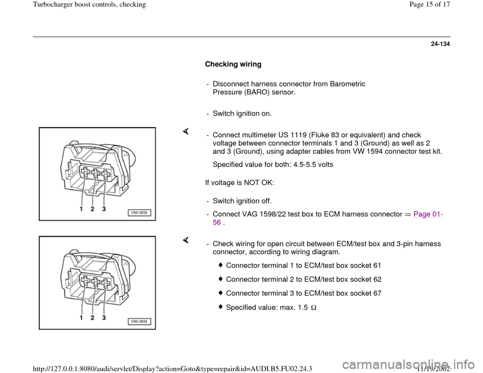
If voltage is NOT OK: - Connect multimeter US 1119 (Fluke 83 or equivalent) and check
voltage between connector terminals 1 and 3 (Ground) as well as 2
and 3 (Ground), using adapter cables from VW 1594 connector test kit.
Specified value for both: 4.5-5.5 volts
- Switch ignition off.
- Connect VAG 1598/22 test box to ECM harness connector Page 01
-
56
.
- Check wiring for open circuit between ECM/test box and 3-pin harness
connector, according to wiring diagram.
Connector terminal 1 to ECM/test box socket 61
Connector terminal 2 to ECM/test box socket 62
Connector terminal 3 to ECM/test box socket 67
Specified value: max. 1.5
Pa
ge 15 of 17 Turbochar
ger boost controls, checkin
g
11/19/2002 htt
p://127.0.0.1:8080/audi/servlet/Dis
play?action=Goto&t
yp
e=re
pair&id=AUDI.B5.FU02.24.3
Page 16 of 17
24-135
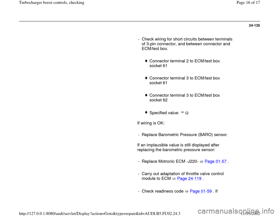
- Check wiring for short circuits between terminals
of 3-pin connector, and between connector and
ECM/test box.
Connector terminal 2 to ECM/test box
socket 61
Connector terminal 3 to ECM/test box
socket 61
Connector terminal 3 to ECM/test box
socket 62
Specified value:
If wiring is OK:
- Replace Barometric Pressure (BARO) sensor.
If an implausible value is still displayed after
replacing the barometric pressure sensor:
- Replace Motronic ECM -J220- Page 01
-57
.
- Carry out adaptation of throttle valve control
module to ECM Page 24
-119
.
-
Check readiness code Page 01
-59
. If
Pa
ge 16 of 17 Turbochar
ger boost controls, checkin
g
11/19/2002 htt
p://127.0.0.1:8080/audi/servlet/Dis
play?action=Goto&t
yp
e=re
pair&id=AUDI.B5.FU02.24.3