fuse box AUDI A8 1999 D2 / 1.G AEB Engine Motronic MFI And Ignition System
[x] Cancel search | Manufacturer: AUDI, Model Year: 1999, Model line: A8, Model: AUDI A8 1999 D2 / 1.GPages: 135, PDF Size: 0.71 MB
Page 6 of 135
BEFORE cranking engine at starting RPM
(e.g. for compression testing) disable ignition
and fuel injection systems:
Disconnect both ignition coil power output
stages, and both Motronic fuses at the E-box
in the plenum.
Disconnect harness connectors from all fuel
injectors.
Afterward, erase DTC memory.
Pa
ge 6 of 135 Motronic Multi
port Fuel In
jection
(MFI
) and i
gnition s
ystem
11/19/2002 htt
p://127.0.0.1:8080/audi/servlet/Dis
play?action=Goto&t
yp
e=re
pair&id=AUDI.B5.FU02.24.1
Page 38 of 135
24-27
Oxygen Sensor (O2S) heater (before
TWC), checking
Notes:
Harness connector for Oxygen Sensor (O2S)
heater: 4-pin, brown
Component locations Page 24
-1 .
Required special tools and test equipment
VAG 1551 or VAG 1552 Scan Tool (ST) with
VAG 1551/3 adapter cable
VAG 1598/22 test box
Multimeter US 1119 (Fluke 83 or equivalent)
VW 1594 connector test kit
Wiring diagram
Test requirements
Fuse for Oxygen Sensor (O2S) heater OK
Pa
ge 38 of 135 Motronic Multi
port Fuel In
jection
(MFI
) and i
gnition s
ystem
11/19/2002 htt
p://127.0.0.1:8080/audi/servlet/Dis
play?action=Goto&t
yp
e=re
pair&id=AUDI.B5.FU02.24.1
Page 57 of 135

24-43
Oxygen Sensor (O2S) heater (behind
TWC), checking
Notes:
Harness connector for Oxygen Sensor (O2S)
heater: 4-pin, black
Component locations Page 24
-1
Required special tools and test equipment
VAG 1551 or VAG 1552 Scan Tool (ST) with
VAG 1551/3 adapter cable
VAG 1598/22 test box
Multimeter US 1119 (Fluke 83 or equivalent)
VW 1594 connector test kit
Wiring diagram
Test requirements
Fuse for Oxygen Sensor (O2S) heater OK
Pa
ge 57 of 135 Motronic Multi
port Fuel In
jection
(MFI
) and i
gnition s
ystem
11/19/2002 htt
p://127.0.0.1:8080/audi/servlet/Dis
play?action=Goto&t
yp
e=re
pair&id=AUDI.B5.FU02.24.1
Page 75 of 135
24-57
Mass Air Flow (MAF) sensor, checking
Required special tools and test equipment
VAG 1551 or VAG 1552 Scan Tool (ST) with
VAG 1551/3 adapter cable
VAG 1598/22 test box
Multimeter US 1119 (Fluke 83 or equivalent)
VW 1594 connector test kit
Wiring diagram
Test requirements
All electrical consumers switched off (coolant
fan must not run during test).
A/C must be switched off
Fuse for MAF sensor OK
Pa
ge 75 of 135 Motronic Multi
port Fuel In
jection
(MFI
) and i
gnition s
ystem
11/19/2002 htt
p://127.0.0.1:8080/audi/servlet/Dis
play?action=Goto&t
yp
e=re
pair&id=AUDI.B5.FU02.24.1
Page 106 of 135
24-79
Evaluation of display group 4 Display group: 4
Display field: 2
Possible cause
Corrective action
No VAG 1551 display
Fuse for ECM faulty- Replace fuse
Open circuit in wiring- Voltage supply at terminal 15 Page 24
-
80
Displayed value changes between 10.0-14.5
V
Intermittent connection - Voltage supply at terminal 30 Page 24
-
79
0.0-10.0 V
Battery
discharged/faulty Voltage regulator faulty - Check battery
- Check generator
- Check voltage regulator
14.5-16.5 V Generator faultyVoltage regulator faulty - Check generator
- Check voltage regulator
Checking voltage supply at terminal 30
- Switch ignition off.
- Connect VAG 1598/22 test box to ECM harness
connector Page 01
-56
.
Pa
ge 106 of 135 Motronic Multi
port Fuel In
jection
(MFI
) and i
gnition s
ystem
11/19/2002 htt
p://127.0.0.1:8080/audi/servlet/Dis
play?action=Goto&t
yp
e=re
pair&id=AUDI.B5.FU02.24.1
Page 116 of 135
24-85
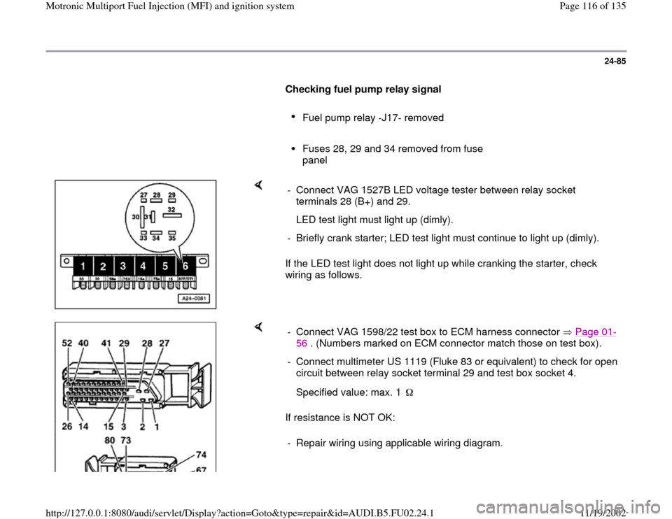
Checking fuel pump relay signal
Fuel pump relay -J17- removed
Fuses 28, 29 and 34 removed from fuse
panel
If the LED test light does not light up while cranking the starter, check
wiring as follows. - Connect VAG 1527B LED voltage tester between relay socket
terminals 28 (B+) and 29.
LED test light must light up (dimly).
- Briefly crank starter; LED test light must continue to light up (dimly).
If resistance is NOT OK: - Connect VAG 1598/22 test box to ECM harness connector Page 01
-
56
. (Numbers marked on ECM connector match those on test box).
- Connect multimeter US 1119 (Fluke 83 or equivalent) to check for open
circuit between relay socket terminal 29 and test box socket 4.
Specified value: max. 1 - Repair wiring using applicable wiring diagram.
Pa
ge 116 of 135 Motronic Multi
port Fuel In
jection
(MFI
) and i
gnition s
ystem
11/19/2002 htt
p://127.0.0.1:8080/audi/servlet/Dis
play?action=Goto&t
yp
e=re
pair&id=AUDI.B5.FU02.24.1
Page 119 of 135
24-87
Fuel injector actuation, checking
Triggering fuel injectors via output Diagnostic
Test Mode (DTM) Page 01
-42
Required special tools and test equipment
VAG 1598/22 test box
Multimeter US 1119 (Fluke 83 or equivalent)
VAG 1527B LED voltage tester
VW 1594 connector test kit
Wiring diagram
Test requirements
Fuse for fuel injectors OK
Engine speed (RPM) sensor OK
Fuel pump relay OK
Pa
ge 119 of 135 Motronic Multi
port Fuel In
jection
(MFI
) and i
gnition s
ystem
11/19/2002 htt
p://127.0.0.1:8080/audi/servlet/Dis
play?action=Goto&t
yp
e=re
pair&id=AUDI.B5.FU02.24.1