AUDI A8 1999 D2 / 1.G AHA Engine Intake Manifold Tuning System Workshop Manual
Manufacturer: AUDI, Model Year: 1999,
Model line: A8,
Model: AUDI A8 1999 D2 / 1.G
Pages: 11, PDF Size: 0.1 MB
AUDI A8 1999 D2 / 1.G AHA Engine Intake Manifold Tuning System Workshop Manual
A8 1999 D2 / 1.G
AUDI
AUDI
https://www.carmanualsonline.info/img/6/1043/w960_1043-0.png
AUDI A8 1999 D2 / 1.G AHA Engine Intake Manifold Tuning System Workshop Manual
Trending: ignition, change time, oil change, wiring diagram, check engine, oil, checking oil
Page 1 of 11
24-154
Intake Manifold Tuning (IMT)
system
Notes:
The change-over of the manifold from long to
short intake path occurs at approx. 4500 RPM.
Component location page 24
-1
Required special tools and test equipment
VAG1551 or VAG1552 Scan Tool (ST) with
VAG1551/3 adapter cable
VAG1598/22 test box
Multimeter US1119 (Fluke 83 or equivalent)
VW1594 connector test kit
VAG1348/3A remote control connection
VAG1348/3-2 adapter cable
VAG1390 hand pump
Pa
ge 1 of 11 Intake Manifold Tunin
g (IMT
) syste
m
11/23/2002 htt
p://127.0.0.1:8080/audi/servlet/Dis
play?action=Goto&t
yp
e=re
pair&id=AUDI.B5.FU03.24.3
Page 2 of 11
Wiring diagrams
Pa
ge 2 of 11 Intake Manifold Tunin
g (IMT
) syste
m
11/23/2002 htt
p://127.0.0.1:8080/audi/servlet/Dis
play?action=Goto&t
yp
e=re
pair&id=AUDI.B5.FU03.24.3
Page 3 of 11
24-155
Intake Manifold Tuning (IMT) function,
checking
Note:
The following test should only be conducted if
performance deficiencies occur.
- Increase engine rpm clearly above 4500 RPM.
Intake manifold tuning vacuum solenoid must be
actuated (solenoid is located on intake manifold,
left-front, under the ignition coils).
If the vacuum solenoid is not actuated:
- Check intake manifold tuning valve -N156-
(change-over valve) page 24
-156
.
- Check vacuum system for leaks page 24
-
162
.
- Check that vacuum lines are correctly installed,
do not leak and are not blocked.
- Check change-over mechanism for ease of
movement (activate change-over linkage by
hand).
Pa
ge 3 of 11 Intake Manifold Tunin
g (IMT
) syste
m
11/23/2002 htt
p://127.0.0.1:8080/audi/servlet/Dis
play?action=Goto&t
yp
e=re
pair&id=AUDI.B5.FU03.24.3
Page 4 of 11
24-156
Intake Manifold Tuning (IMT) valve,
checking
Notes:
Without current the tuning -N156- is closed.
Component locations page 24
-1
Checking flow and for leaks
- Remove intake manifold tuning valve -N156-.
- After removing, re-connect valve -N156- to
harness connector.
- Conduct output Diagnostic Test Mode (DTM) for
intake manifold tuning valve -N156- page 01
-
51
.
- Blow through hose to valve output DTM and
make sure that -N156- opens and closes
correctly.
If -N156- does not open and close:
- Replace intake manifold tuning valve -N156-.
Pa
ge 4 of 11 Intake Manifold Tunin
g (IMT
) syste
m
11/23/2002 htt
p://127.0.0.1:8080/audi/servlet/Dis
play?action=Goto&t
yp
e=re
pair&id=AUDI.B5.FU03.24.3
Page 5 of 11
24-157
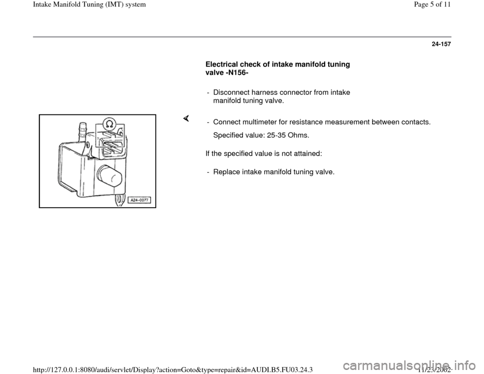
Electrical check of intake manifold tuning
valve -N156-
- Disconnect harness connector from intake
manifold tuning valve.
If the specified value is not attained:
- Connect multimeter for resistance measurement between contacts.
Specified value: 25-35 Ohms.
- Replace intake manifold tuning valve.
Pa
ge 5 of 11 Intake Manifold Tunin
g (IMT
) syste
m
11/23/2002 htt
p://127.0.0.1:8080/audi/servlet/Dis
play?action=Goto&t
yp
e=re
pair&id=AUDI.B5.FU03.24.3
Page 6 of 11
24-158
Checking voltage supply for intake manifold
tuning valve -N156-
Test requirements
Fuse for for intake manifold tuning valve OK
- Disconnect harness connector from intake manifold tuning valve.
If LED does not light up: - Connect LED test lamp VAG1527 with wires from test kit VAG1594
between terminal 1 (B+) of 2-pin connector and engine Ground.
- Crank starter.
LED must light up.
- Check fuse for -N156-
Pa
ge 6 of 11 Intake Manifold Tunin
g (IMT
) syste
m
11/23/2002 htt
p://127.0.0.1:8080/audi/servlet/Dis
play?action=Goto&t
yp
e=re
pair&id=AUDI.B5.FU03.24.3
Page 7 of 11
24-159
- Check wiring from terminal 1 of 2-pin connector
to fuse per wiring diagram for continuity.
Specified value: max. 1 Ohm
If wiring is OK:
- Check fuel pump relay and signal to relay
page 24
-95
.
Pa
ge 7 of 11 Intake Manifold Tunin
g (IMT
) syste
m
11/23/2002 htt
p://127.0.0.1:8080/audi/servlet/Dis
play?action=Goto&t
yp
e=re
pair&id=AUDI.B5.FU03.24.3
Page 8 of 11
24-160
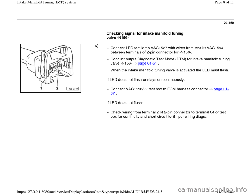
Checking signal for intake manifold tuning
valve -N156-
If LED does not flash or stays on continuously:
If LED does not flash: - Connect LED test lamp VAG1527 with wires from test kit VAG1594
between terminals of 2-pin connector for -N156-.
- Conduct output Diagnostic Test Mode (DTM) for intake manifold tuning
valve -N156- page 01
-51
.
When the intake manifold tuning valve is activated the LED must flash.
- Connect VAG1598/22 test box to ECM harness connector page 01
-
67
.
- Check wiring from terminal 2 of 2-pin connector to terminal 64 of test
box for continuity and short circuit to B+ per wiring diagram.
Pa
ge 8 of 11 Intake Manifold Tunin
g (IMT
) syste
m
11/23/2002 htt
p://127.0.0.1:8080/audi/servlet/Dis
play?action=Goto&t
yp
e=re
pair&id=AUDI.B5.FU03.24.3
Page 9 of 11
24-161
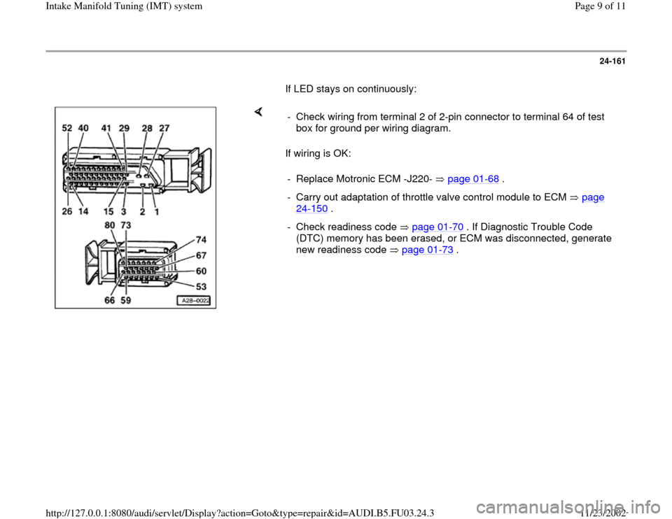
If LED stays on continuously:
If wiring is OK: - Check wiring from terminal 2 of 2-pin connector to terminal 64 of test
box for ground per wiring diagram.
- Replace Motronic ECM -J220- page 01
-68
.
- Carry out adaptation of throttle valve control module to ECM page
24
-150
.
- Check readiness code page 01
-70
. If Diagnostic Trouble Code
(DTC) memory has been erased, or ECM was disconnected, generate
new readiness code page 01
-73
.
Pa
ge 9 of 11 Intake Manifold Tunin
g (IMT
) syste
m
11/23/2002 htt
p://127.0.0.1:8080/audi/servlet/Dis
play?action=Goto&t
yp
e=re
pair&id=AUDI.B5.FU03.24.3
Page 10 of 11
24-162
Vacuum system, checking for leaks
- Let engine run 2 to 3 minutes at idle (for vacuum
to build up).
- Switch ignition off.
- Remove 2-pin connector from intake manifold
tuning valve -N156- (change-over valve).
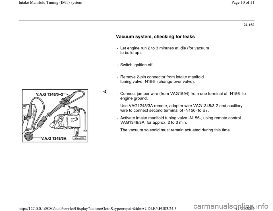
- Connect jumper wire (from VAG1594) from one terminal of -N156- to
engine ground.
- Use VAG1248/3A remote, adapter wire VAG1348/3-2 and auxiliary
wire to connect second terminal of -N156- to B+.
- Activate intake manifold tuning valve -N156-, using remote control
VAG1348/3A, for approx. 2 to 3 min.
The vacuum solenoid must remain actuated during this time.
Pa
ge 10 of 11 Intake Manifold Tunin
g (IMT
) syste
m
11/23/2002 htt
p://127.0.0.1:8080/audi/servlet/Dis
play?action=Goto&t
yp
e=re
pair&id=AUDI.B5.FU03.24.3
Trending: check engine, oil, remote control, fuel pump, checking oil, oil change, relay
