engine AUDI A8 1999 D2 / 1.G AEB Engine OBD and DTC
[x] Cancel search | Manufacturer: AUDI, Model Year: 1999, Model line: A8, Model: AUDI A8 1999 D2 / 1.GPages: 57, PDF Size: 0.2 MB
Page 1 of 57
01-1
On Board Diagnostic (OBD)
Function
The Multiport Fuel Injection (MFI) system is
equipped with an Engine Control Module (ECM) -
J220- with On Board Diagnostic (OBD)
capability.
When malfunctions occur in sensors or
components monitored by OBD, Diagnostic
Trouble Codes (DTC) are stored in DTC
memory.
Stored DTCs are identified using the VAG 1551
Scan Tool (ST) Page 01
-15
.
After the necessary repairs are completed, DTC
memory must be erased Page 01
-40
.
OBD II legal regulations require a display
(readiness code) that shows inspection
readiness for the annual exhaust emissions test.
The readiness code shows that every component
and/or system that affects exhaust emissions,
which can lead to the Malfunction Indicator Lamp
(MIL) being switched on, has been operated at
least once with positive results.
The readiness code is reset and/or erased and
must be regenerated every time DTC memory is
erased, the power supply to the ECM -J220- is
interrupted (example: when connecting test box
Pa
ge 1 of 57 On Board Dia
gnostic
(OBD
)
11/19/2002 htt
p://127.0.0.1:8080/audi/servlet/Dis
play?action=Goto&t
yp
e=re
pair&id=AUDI.B5.FU02.01.1
Page 3 of 57
01-2
Malfunction Indicator Lamp (MIL)
function, checking
If a malfunction is recognized by the Engine
Control Module (ECM), this is indicated by the
MIL coming on.
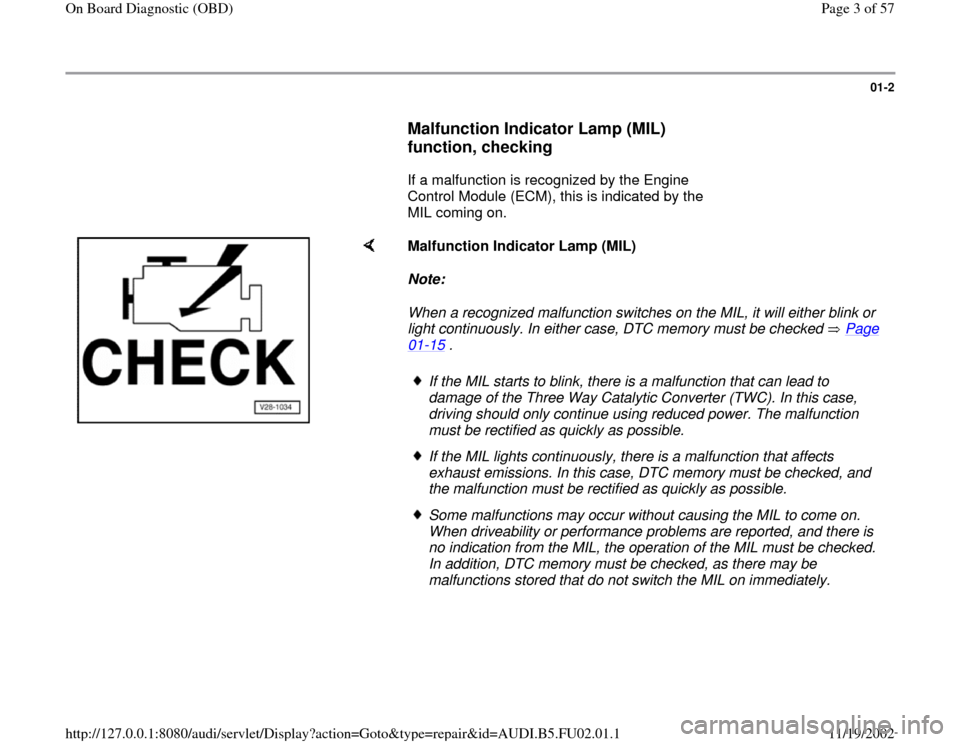
Malfunction Indicator Lamp (MIL)
Note:
When a recognized malfunction switches on the MIL, it will either blink or
light continuously. In either case, DTC memory must be checked Page 01
-15
.
If the MIL starts to blink, there is a malfunction that can lead to
damage of the Three Way Catalytic Converter (TWC). In this case,
driving should only continue using reduced power. The malfunction
must be rectified as quickly as possible. If the MIL lights continuously, there is a malfunction that affects
exhaust emissions. In this case, DTC memory must be checked, and
the malfunction must be rectified as quickly as possible. Some malfunctions may occur without causing the MIL to come on.
When driveability or performance problems are reported, and there is
no indication from the MIL, the operation of the MIL must be checked.
In addition, DTC memory must be checked, as there may be
malfunctions stored that do not switch the MIL on immediately.
Pa
ge 3 of 57 On Board Dia
gnostic
(OBD
)
11/19/2002 htt
p://127.0.0.1:8080/audi/servlet/Dis
play?action=Goto&t
yp
e=re
pair&id=AUDI.B5.FU02.01.1
Page 6 of 57
01-4
If MIL lights up when ignition is switched on,
continue checking as follows:
- Start engine and let run at idle.
MIL must go out after a few seconds.
If MIL does not go out:
- Check Diagnostic Trouble Code (DTC) memory
Page 01
-15
.
If there are no malfunctions stored in DTC
memory: Cause:
MIL is triggered continuously due to short
circuit to Ground. Remedy:
- Switch ignition off.
- Connect VAG 1598/22 test box.
- Check resistance between test box socket 17 and vehicle Ground,
specified value: (no continuity) If the specified value is not obtained:
- Check for short circuit to Ground in wiring from Motronic Engine Control
Module (ECM) -J220- to MIL.
- Trace malfunction using applicable wiring diagram and repair as
necessary.
Pa
ge 6 of 57 On Board Dia
gnostic
(OBD
)
11/19/2002 htt
p://127.0.0.1:8080/audi/servlet/Dis
play?action=Goto&t
yp
e=re
pair&id=AUDI.B5.FU02.01.1
Page 8 of 57
01-5
On Board Diagnostic (OBD) technical data
Memory
Temporary memory and permanent memory (If the engine control module is disconnected from the Battery Positive
Voltage (B+) supply, the readiness code and learning values will be erased. Any malfunctions stored in DTC memory are
not erased)
Data output
Rapid data transfer
Additional malfunction indication by Malfunction Indicator Lamp (MIL) lighting up
ECM identification
Page 01
-7 ; VAG 1551 Scan Tool (ST), connecting and selecting "Engine Electronics" address word 01
ECM functions
The Motronic ECM -J220- performs different OBD functions, carried out with the ignition switched on or with the engine
running. Following are the conditions required to carry out each of the specific functions.
Address words:
Address word 00: Automatic Test Sequence r Ignition switched on -or- Engine running at idle
Address word 01: Engine Electronics r Ignition switched on -or- Engine running at idle
Address word 33: OBD II (generic scan tool) r Ignition switched on -or- Engine running at idle
Pa
ge 8 of 57 On Board Dia
gnostic
(OBD
)
11/19/2002 htt
p://127.0.0.1:8080/audi/servlet/Dis
play?action=Goto&t
yp
e=re
pair&id=AUDI.B5.FU02.01.1
Page 9 of 57
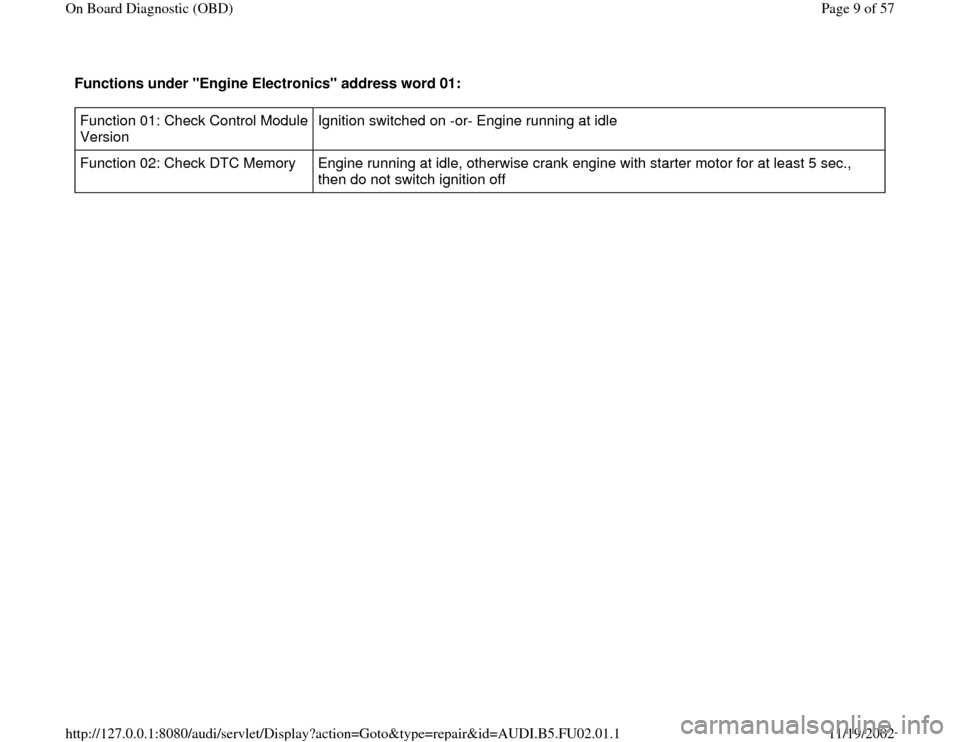
Functions under "Engine Electronics" address word 01: Function 01: Check Control Module
Version Ignition switched on -or- Engine running at idle
Function 02: Check DTC Memory Engine running at idle, otherwise crank engine with starter motor for at least 5 sec.,
then do not switch ignition off
Pa
ge 9 of 57 On Board Dia
gnostic
(OBD
)
11/19/2002 htt
p://127.0.0.1:8080/audi/servlet/Dis
play?action=Goto&t
yp
e=re
pair&id=AUDI.B5.FU02.01.1
Page 10 of 57
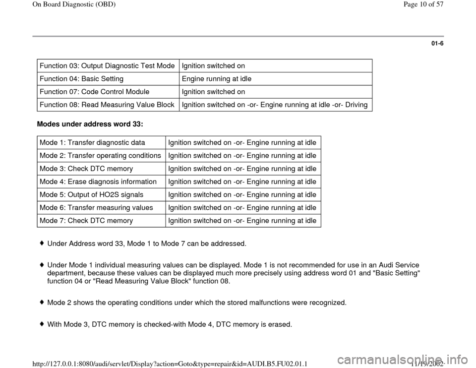
01-6
Function 03: Output Diagnostic Test Mode Ignition switched on
Function 04: Basic Setting Engine running at idle
Function 07: Code Control Module Ignition switched on
Function 08: Read Measuring Value Block Ignition switched on -or- Engine running at idle -or- Driving Modes under address word 33: Mode 1: Transfer diagnostic data Ignition switched on -or- Engine running at idle
Mode 2: Transfer operating conditions Ignition switched on -or- Engine running at idle
Mode 3: Check DTC memory Ignition switched on -or- Engine running at idle
Mode 4: Erase diagnosis information Ignition switched on -or- Engine running at idle
Mode 5: Output of HO2S signals Ignition switched on -or- Engine running at idle
Mode 6: Transfer measuring values Ignition switched on -or- Engine running at idle
Mode 7: Check DTC memory Ignition switched on -or- Engine running at idle Under Address word 33, Mode 1 to Mode 7 can be addressed.
Under Mode 1 individual measuring values can be displayed. Mode 1 is not recommended for use in an Audi Service
department, because these values can be displayed much more precisely using address word 01 and "Basic Setting"
function 04 or "Read Measuring Value Block" function 08.
Mode 2 shows the operating conditions under which the stored malfunctions were recognized.
With Mode 3, DTC memory is checked-with Mode 4, DTC memory is erased.
Pa
ge 10 of 57 On Board Dia
gnostic
(OBD
)
11/19/2002 htt
p://127.0.0.1:8080/audi/servlet/Dis
play?action=Goto&t
yp
e=re
pair&id=AUDI.B5.FU02.01.1
Page 12 of 57
01-7
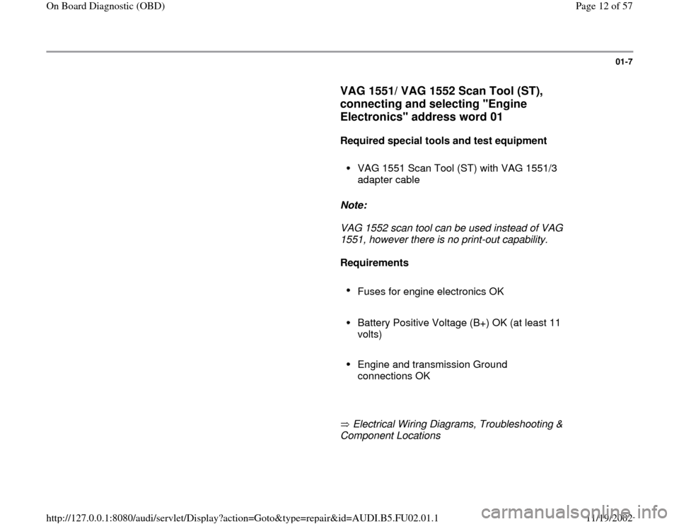
VAG 1551/ VAG 1552 Scan Tool (ST),
connecting and selecting "Engine
Electronics" address word 01
Required special tools and test equipment
VAG 1551 Scan Tool (ST) with VAG 1551/3
adapter cable
Note:
VAG 1552 scan tool can be used instead of VAG
1551, however there is no print-out capability.
Requirements
Fuses for engine electronics OK
Battery Positive Voltage (B+) OK (at least 11
volts)
Engine and transmission Ground
connections OK
Electrical Wiring Diagrams, Troubleshooting &
Component Locations
Pa
ge 12 of 57 On Board Dia
gnostic
(OBD
)
11/19/2002 htt
p://127.0.0.1:8080/audi/servlet/Dis
play?action=Goto&t
yp
e=re
pair&id=AUDI.B5.FU02.01.1
Page 14 of 57
01-8
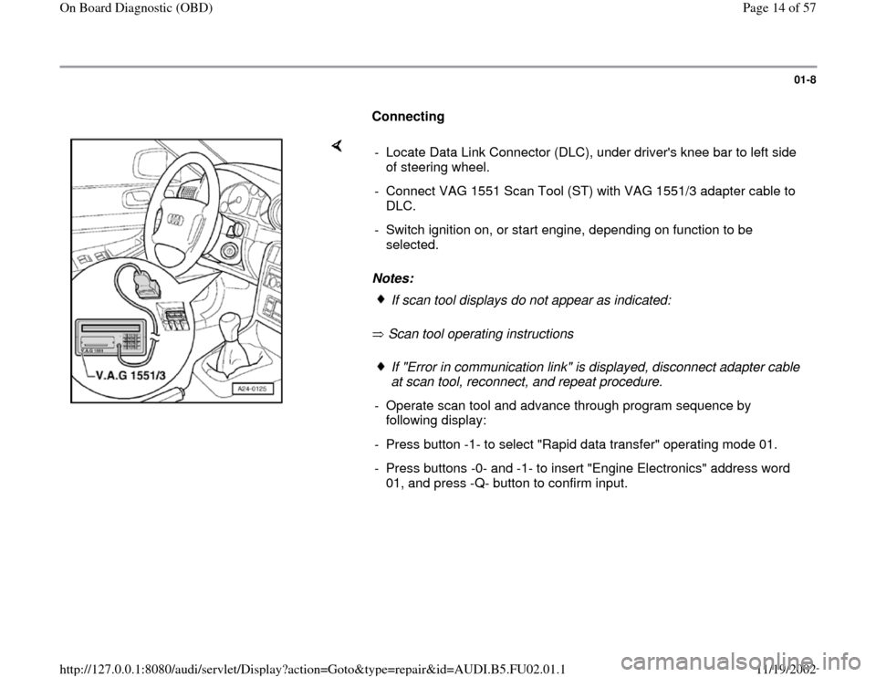
Connecting
Notes:
Scan tool operating instructions - Locate Data Link Connector (DLC), under driver's knee bar to left side
of steering wheel.
- Connect VAG 1551 Scan Tool (ST) with VAG 1551/3 adapter cable to
DLC.
- Switch ignition on, or start engine, depending on function to be
selected.
If scan tool displays do not appear as indicated:If "Error in communication link" is displayed, disconnect adapter cable
at scan tool, reconnect, and repeat procedure.
- Operate scan tool and advance through program sequence by
following display:
- Press button -1- to select "Rapid data transfer" operating mode 01.
- Press buttons -0- and -1- to insert "Engine Electronics" address word
01, and press -Q- button to confirm input.
Pa
ge 14 of 57 On Board Dia
gnostic
(OBD
)
11/19/2002 htt
p://127.0.0.1:8080/audi/servlet/Dis
play?action=Goto&t
yp
e=re
pair&id=AUDI.B5.FU02.01.1
Page 15 of 57
01-9
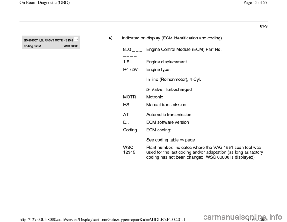
8D0907557 1,8L R4/5VT MOTR HS D02 Coding 06051
WSC 00000
Indicated on display (ECM identification and coding)
8D0 _ _ _
_ _ _ _ Engine Control Module (ECM) Part No.
1.8 L Engine displacement
R4 / 5VT Engine type:
In-line (Reihenmotor), 4-Cyl.
5- Valve, Turbocharged
MOTR Motronic
HS
AT Manual transmission
Automatic transmission
D.. ECM software version
Coding ECM coding:
See coding table page WSC
12345 Plant number: indicates where the VAG 1551 scan tool was
used for the last coding and/or adaptation (as long as factory
coding has not been changed, WSC 00000 is displayed)
Pa
ge 15 of 57 On Board Dia
gnostic
(OBD
)
11/19/2002 htt
p://127.0.0.1:8080/audi/servlet/Dis
play?action=Goto&t
yp
e=re
pair&id=AUDI.B5.FU02.01.1
Page 17 of 57
01-11
Code Control Module (function 07)
If vehicle coding information is not as specified,
or if the ECM has been replaced, the ECM must
be coded as follows.
Required special tools and test equipment
VAG 1551/ VAG 1552 Scan Tool (ST) with VAG
1551/3 adapter cable
Coding procedure
- Connect VAG 1551/ VAG 1552 Scan Tool (ST)
and press buttons -0- and -1- to insert "Engine
Electronics" address word 01 (ignition switched
on) Page 01
-7 .
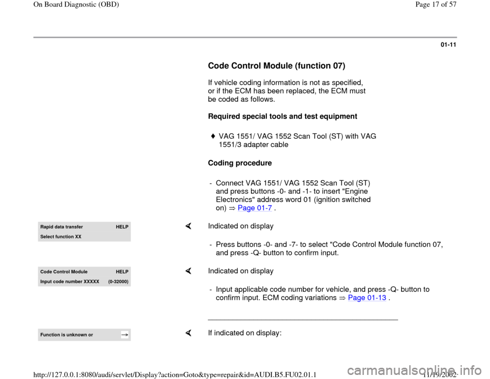
Rapid data transfer
HELP
Select function XX
Indicated on display
- Press buttons -0- and -7- to select "Code Control Module function 07,
and press -Q- button to confirm input.
Code Control Module
HELP
Input code number XXXXX
(0-32000
)
Indicated on display
______________________________________________ - Input applicable code number for vehicle, and press -Q- button to
confirm input. ECM coding variations Page 01
-13
.
Function is unknown or
If indicated on display:
Pa
ge 17 of 57 On Board Dia
gnostic
(OBD
)
11/19/2002 htt
p://127.0.0.1:8080/audi/servlet/Dis
play?action=Goto&t
yp
e=re
pair&id=AUDI.B5.FU02.01.1