automatic transmission AUDI A8 2000 D2 / 1.G 01V Transmission Electrical Testing User Guide
[x] Cancel search | Manufacturer: AUDI, Model Year: 2000, Model line: A8, Model: AUDI A8 2000 D2 / 1.GPages: 66, PDF Size: 0.28 MB
Page 37 of 66
Electrical Wiring Diagrams & Component Locations binder A) Signal is transmitted to Transmission Control Module (TCM) via the Engine Control Module (ECM). Test is only for vehicles
without CAN-Bus
Repair Manual, 5 Spd. Automatic Transmission 01V, Repair Group 00; Code letters, aggregate allocation, ratios, equipment
3) Pin 28 at the control module is vacant for vehicles with 10-pin connector of multi-function switch -F125-.
Pa
ge 37 of 66 Electrical testin
g
11/20/2002 htt
p://127.0.0.1:8080/audi/servlet/Dis
play?action=Goto&t
yp
e=re
pair&id=AUDI.B5.AT02.01.16
Page 39 of 66
Repair Manual, 5 Spd. Automatic Transmission 01V, Repair Group 00; Code letters, aggregate allocation, ratios,
equipment
3) Pin 28 at the control module is vacant for vehicles with 10-pin connector of multi-function switch -F125-.
Pa
ge 39 of 66 Electrical testin
g
11/20/2002 htt
p://127.0.0.1:8080/audi/servlet/Dis
play?action=Goto&t
yp
e=re
pair&id=AUDI.B5.AT02.01.16
Page 40 of 66
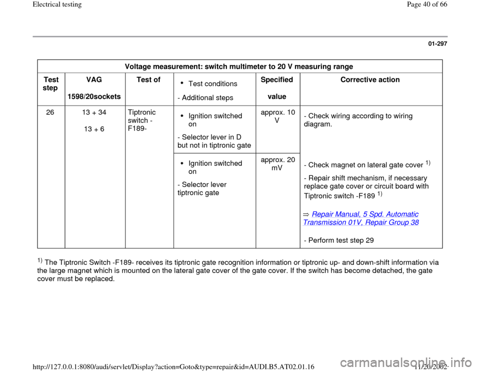
01-297
Voltage measurement: switch multimeter to 20 V measuring range
Test
step VAG
1598/20sockets Test of
Test conditions
- Additional stepsSpecified
value Corrective action
26 13 + 34
13 + 6 Tiptronic
switch -
F189- Ignition switched
on
- Selector lever in D
but not in tiptronic gateapprox. 10
V - Check wiring according to wiring
diagram.
Ignition switched
on
- Selector lever
tiptronic gate approx. 20
mV
Repair Manual, 5 Spd. Automatic
Transmission 01V, Repair Group 38
- Check magnet on lateral gate cover
1)
- Repair shift mechanism, if necessary
replace gate cover or circuit board with
Tiptronic switch -F189
1)
- Perform test step 29
1) The Tiptronic Switch -F189- receives its tiptronic gate recognition information or tiptronic up- and down-shift information via
the large magnet which is mounted on the lateral gate cover of the gate cover. If the switch has become detached, the gate
cover must be replaced.
Pa
ge 40 of 66 Electrical testin
g
11/20/2002 htt
p://127.0.0.1:8080/audi/servlet/Dis
play?action=Goto&t
yp
e=re
pair&id=AUDI.B5.AT02.01.16
Page 41 of 66
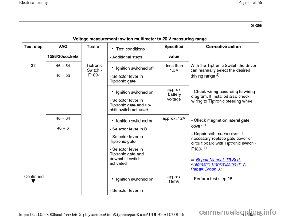
01-298
Voltage measurement: switch multimeter to 20 V measuring range
Test step
VAG
1598/20sockets Test of
Test conditions
- Additional stepsSpecified
value Corrective action
27
46 + 54
46 + 55 Tiptronic
Switch -
F189- Ignition switched off
- Selector lever in
Tiptronic gate less than
1.5V With the Tiptronic Switch the driver
can manually select the desired
driving range
2)
Ignition switched on
- Selector lever in
Tiptronic gate and up-
shift switch actuated approx.
battery
voltage - Check wiring according to wiring
diagram. If installed also check
wiring to Tiptronic steering wheel
46 + 34
46 + 6 Ignition switched on
- Selector lever in D
- Selector lever in
Tiptronic gate
- Selector lever in
Tiptronic gate and
downshift switch
activated approx. 12V
Repair Manual, T5 Spd.
Automatic Transmission 01V, Repair Group 37
- Check magnet on lateral gate
cover
1)
- Repair shift mechanism, if
necessary replace gate cover or
circuit board with Tiptronic switch -
F189- 1)
Continued
Ignition switched on
- Selector lever in approx.
15mV - Perform test step 28
Pa
ge 41 of 66 Electrical testin
g
11/20/2002 htt
p://127.0.0.1:8080/audi/servlet/Dis
play?action=Goto&t
yp
e=re
pair&id=AUDI.B5.AT02.01.16
Page 43 of 66
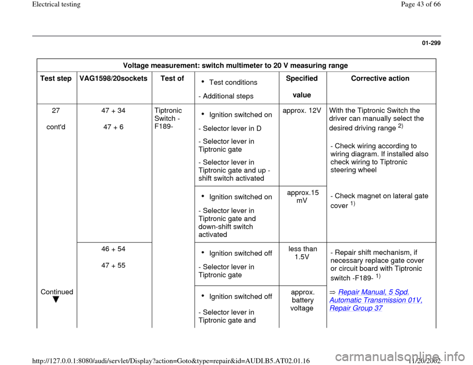
01-299
Voltage measurement: switch multimeter to 20 V measuring range
Test step
VAG1598/20sockets
Test of
Test conditions
- Additional stepsSpecified
value Corrective action
27
cont'd 47 + 34
47 + 6 Tiptronic
Switch -
F189- Ignition switched on
- Selector lever in D
- Selector lever in
Tiptronic gate
- Selector lever in
Tiptronic gate and up -
shift switch activated approx. 12V With the Tiptronic Switch the
driver can manually select the
desired driving range
2)
- Check wiring according to
wiring diagram. If installed also
check wiring to Tiptronic
steering wheel
Ignition switched on
- Selector lever in
Tiptronic gate and
down-shift switch
activated approx.15
mV - Check magnet on lateral gate
cover
1)
46 + 54
47 + 55
Ignition switched off
- Selector lever in
Tiptronic gate less than
1.5V - Repair shift mechanism, if
necessary replace gate cover
or circuit board with Tiptronic
switch -F189-
1)
Continued
Ignition switched off
- Selector lever in
Tiptronic gate and approx.
battery
voltage Repair Manual, 5 Spd.
Automatic Transmission 01V, Repair Group 37
Pa
ge 43 of 66 Electrical testin
g
11/20/2002 htt
p://127.0.0.1:8080/audi/servlet/Dis
play?action=Goto&t
yp
e=re
pair&id=AUDI.B5.AT02.01.16
Page 47 of 66
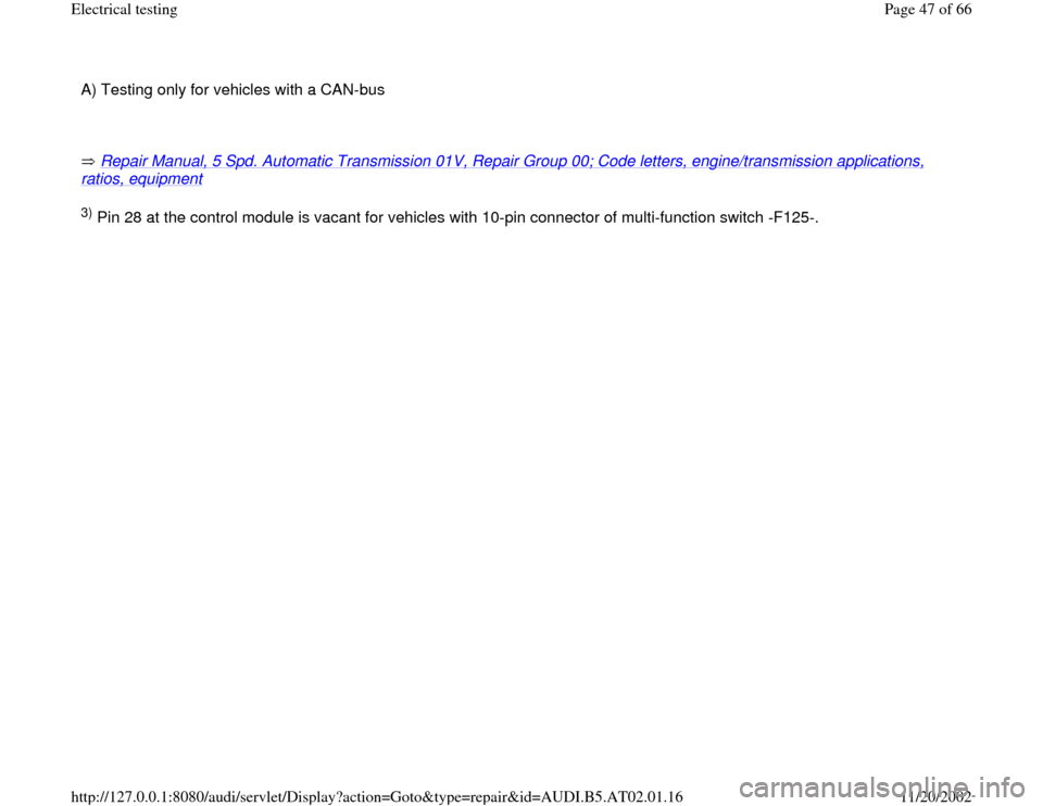
A) Testing only for vehicles with a CAN-bus
Repair Manual, 5 Spd. Automatic Transmission 01V, Repair Group 00; Code letters, engine/transmission applications, ratios, equipment
3) Pin 28 at the control module is vacant for vehicles with 10-pin connector of multi-function switch -F125-.
Pa
ge 47 of 66 Electrical testin
g
11/20/2002 htt
p://127.0.0.1:8080/audi/servlet/Dis
play?action=Goto&t
yp
e=re
pair&id=AUDI.B5.AT02.01.16
Page 52 of 66
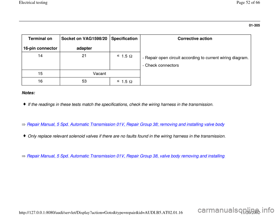
01-305
Terminal on
16-pin connector Socket on VAG1598/20
adapter Specification
Corrective action
14 21
1.5
- Repair open circuit according to current wiring diagram.
- Check connectors
15 Vacant
16 53
1.5
Notes:
If the readings in these tests match the specifications, check the wiring harness in the transmission.
Repair Manual, 5 Spd. Automatic Transmission 01V, Repair Group 38; removing and installing valve body
Only replace relevant solenoid valves if there are no faults found in the wiring harness in the transmission.
Repair Manual, 5 Spd. Automatic Transmission 01V, Repair Group 38, valve body removing and installing
Pa
ge 52 of 66 Electrical testin
g
11/20/2002 htt
p://127.0.0.1:8080/audi/servlet/Dis
play?action=Goto&t
yp
e=re
pair&id=AUDI.B5.AT02.01.16
Page 55 of 66
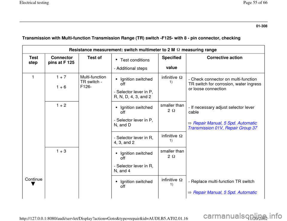
01-308
Transmission with Multi-function Transmission Range (TR) switch -F125- with 8 - pin connector, checking
Resistance measurement: switch multimeter to 2 M measuring range
Test
step Connector
pins at F 125 Test of
Test conditions
- Additional stepsSpecified
value Corrective action
1 1 + 7
1 + 6 Multi-function
TR switch -
F126- Ignition switched
off
- Selector lever in P,
R, N, D, 4, 3, and 2 infinitive
1)
- Check connector on multi-function
TR switch for corrosion, water ingress
or loose connection
1 + 2
Ignition switched
off
- Selector lever in P,
N, and D smaller than
2
Repair Manual, 5 Spd. Automatic
Transmission 01V, Repair Group 37
- If necessary adjust selector lever
cable
- Selector lever in R,
4, 3, and 2 infinitive
1)
1 + 3
Ignition switched
off
- Selector lever in R,
N, and 4 smaller than
2
Continue
Ignition switched
off infinitive
1)
Repair Manual, 5 Spd. Automatic - Replace multi-function TR switch
Pa
ge 55 of 66 Electrical testin
g
11/20/2002 htt
p://127.0.0.1:8080/audi/servlet/Dis
play?action=Goto&t
yp
e=re
pair&id=AUDI.B5.AT02.01.16
Page 57 of 66
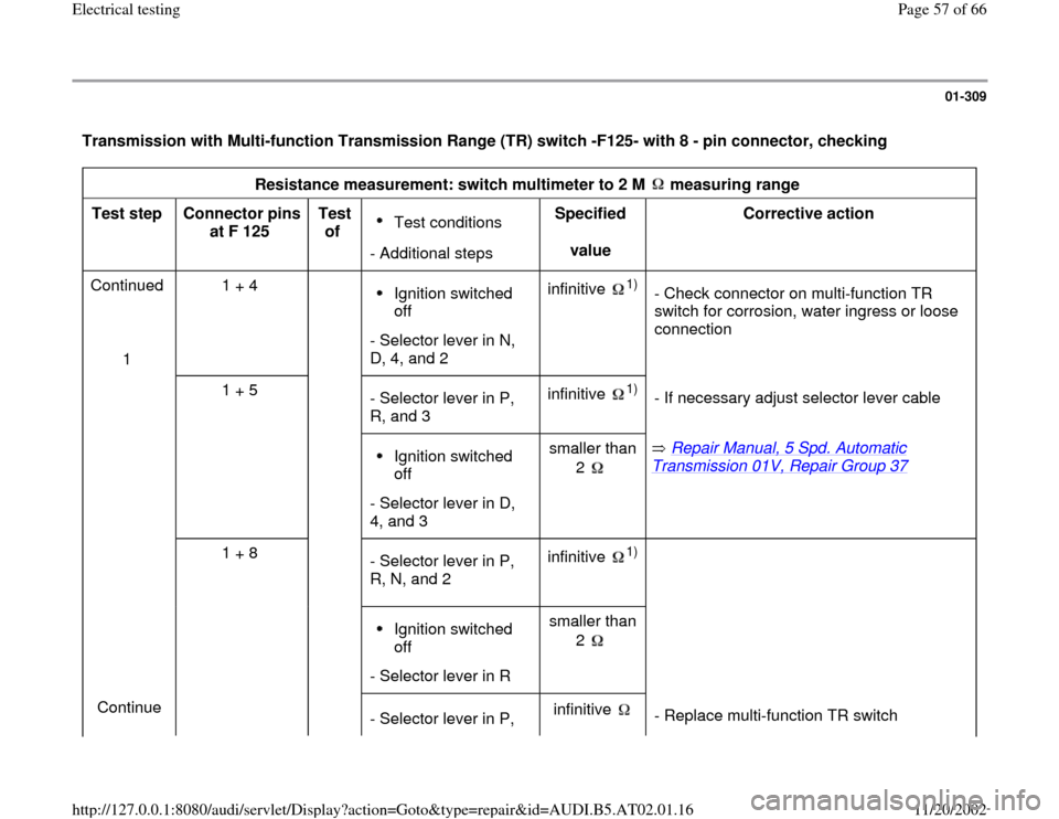
01-309
Transmission with Multi-function Transmission Range (TR) switch -F125- with 8 - pin connector, checking
Resistance measurement: switch multimeter to 2 M measuring range
Test step
Connector pins
at F 125 Test
of
Test conditions
- Additional stepsSpecified
value Corrective action
Continued
1 1 + 4 Ignition switched
off
- Selector lever in N,
D, 4, and 2 infinitive
1)
- Check connector on multi-function TR
switch for corrosion, water ingress or loose
connection
1 + 5
- Selector lever in P,
R, and 3 infinitive
1)
- If necessary adjust selector lever cable
Ignition switched
off
- Selector lever in D,
4, and 3 smaller than
2
Repair Manual, 5 Spd. Automatic
Transmission 01V, Repair Group 37
1 + 8
- Selector lever in P,
R, N, and 2 infinitive
1)
Ignition switched
off
- Selector lever in Rsmaller than
2
Continue
- Selector lever in P, infinitive
- Replace multi-function TR switch
Pa
ge 57 of 66 Electrical testin
g
11/20/2002 htt
p://127.0.0.1:8080/audi/servlet/Dis
play?action=Goto&t
yp
e=re
pair&id=AUDI.B5.AT02.01.16
Page 58 of 66
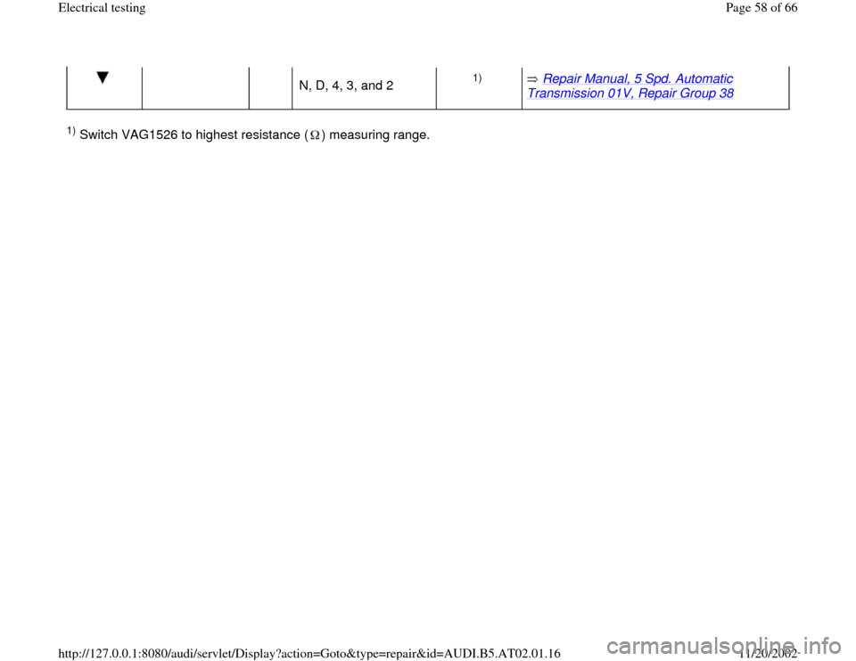
N, D, 4, 3, and 2
1)
Repair Manual, 5 Spd. Automatic
Transmission 01V, Repair Group 38
1) Switch VAG1526 to highest resistance ( ) measuring range.
Pa
ge 58 of 66 Electrical testin
g
11/20/2002 htt
p://127.0.0.1:8080/audi/servlet/Dis
play?action=Goto&t
yp
e=re
pair&id=AUDI.B5.AT02.01.16