light AUDI A8 2000 D2 / 1.G 01V Transmission Remove And Install Workshop Manual
[x] Cancel search | Manufacturer: AUDI, Model Year: 2000, Model line: A8, Model: AUDI A8 2000 D2 / 1.GPages: 64, PDF Size: 1.44 MB
Page 16 of 64
37-86
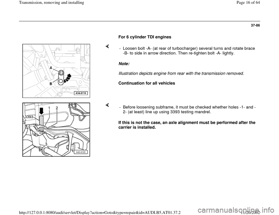
For 6 cylinder TDI engines
Note:
Illustration depicts engine from rear with the transmission removed.
Continuation for all vehicles - Loosen bolt -A- (at rear of turbocharger) several turns and rotate brace
-B- to side in arrow direction. Then re-tighten bolt -A- lightly.
If this is not the case, an axle alignment must be performed after the
carrier is installed. - Before loosening subframe, it must be checked whether holes -1- and -
2- (at least) line up using 3393 testing mandrel.
Pa
ge 16 of 64 Transmission, removin
g and installin
g
11/20/2002 htt
p://127.0.0.1:8080/audi/servlet/Dis
play?action=Goto&t
yp
e=re
pair&id=AUDI.B5.AT01.37.2
Page 17 of 64
37-87
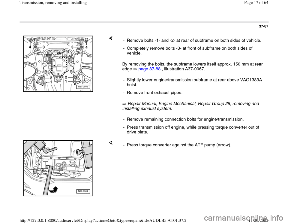
By removing the bolts, the subframe lowers itself approx. 150 mm at rear
edge page 37
-88
, illustration A37-0067.
Repair Manual, Engine Mechanical, Repair Group 26; removing and
installing exhaust system. - Remove bolts -1- and -2- at rear of subframe on both sides of vehicle.
- Completely remove bolts -3- at front of subframe on both sides of
vehicle.
- Slightly lower engine/transmission subframe at rear above VAG1383A
hoist.
- Remove front exhaust pipes:- Remove remaining connection bolts for engine/transmission.
- Press transmission off engine, while pressing torque converter out of
drive plate.
- Press torque converter against the ATF pump (arrow).
Pa
ge 17 of 64 Transmission, removin
g and installin
g
11/20/2002 htt
p://127.0.0.1:8080/audi/servlet/Dis
play?action=Goto&t
yp
e=re
pair&id=AUDI.B5.AT01.37.2
Page 24 of 64
37-94
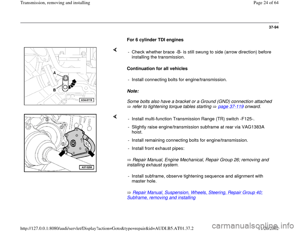
For 6 cylinder TDI engines
Continuation for all vehicles
Note:
Some bolts also have a bracket or a Ground (GND) connection attached
refer to tightening torque tables starting page 37
-119
onward. - Check whether brace -B- is still swung to side (arrow direction) before
installing the transmission.
- Install connecting bolts for engine/transmission.
Repair Manual, Engine Mechanical, Repair Group 26; removing and
installing exhaust system.
Repair Manual, Suspension, Wheels, Steering, Repair Group 40;
Subframe, removing and installing
- Install multi-function Transmission Range (TR) switch -F125-.
- Slightly raise engine/transmission subframe at rear via VAG1383A
hoist.
- Install remaining connecting bolts for engine/transmission.
- Install front exhaust pipes:
- Install subframe, observe tightening sequence and alignment with
master hole.
Pa
ge 24 of 64 Transmission, removin
g and installin
g
11/20/2002 htt
p://127.0.0.1:8080/audi/servlet/Dis
play?action=Goto&t
yp
e=re
pair&id=AUDI.B5.AT01.37.2
Page 26 of 64
37-96
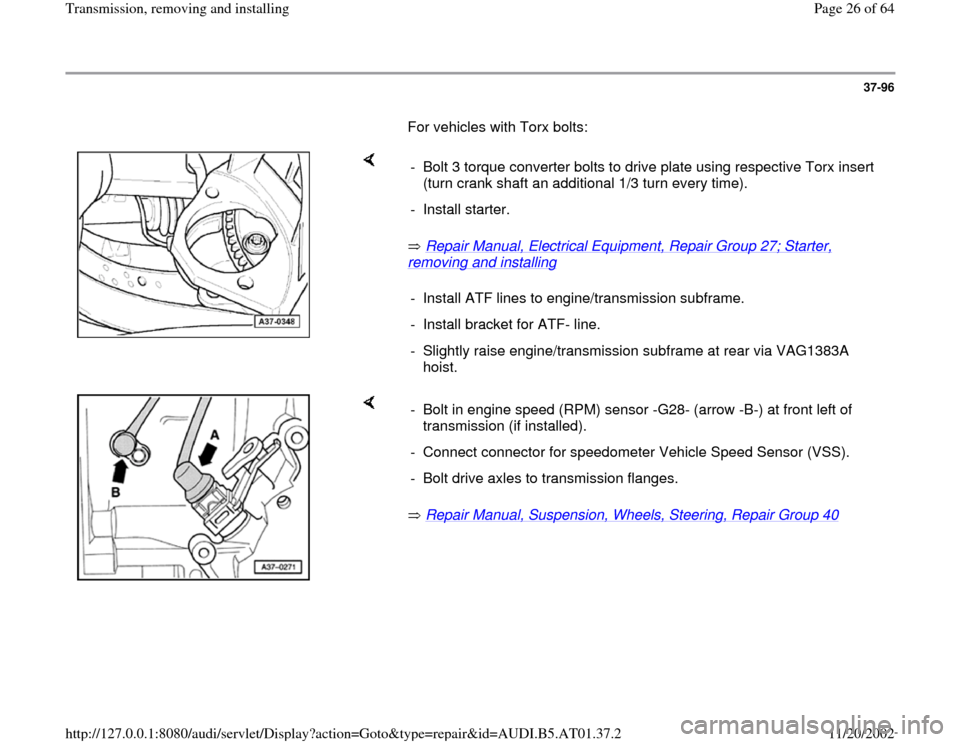
For vehicles with Torx bolts:
Repair Manual, Electrical Equipment, Repair Group 27; Starter,
removing and installing
- Bolt 3 torque converter bolts to drive plate using respective Torx insert
(turn crank shaft an additional 1/3 turn every time).
- Install starter.
- Install ATF lines to engine/transmission subframe.
- Install bracket for ATF- line.
- Slightly raise engine/transmission subframe at rear via VAG1383A
hoist.
Repair Manual, Suspension, Wheels, Steering, Repair Group 40
- Bolt in engine speed (RPM) sensor -G28- (arrow -B-) at front left of
transmission (if installed).
- Connect connector for speedometer Vehicle Speed Sensor (VSS).
- Bolt drive axles to transmission flanges.
Pa
ge 26 of 64 Transmission, removin
g and installin
g
11/20/2002 htt
p://127.0.0.1:8080/audi/servlet/Dis
play?action=Goto&t
yp
e=re
pair&id=AUDI.B5.AT01.37.2
Page 35 of 64
37-105
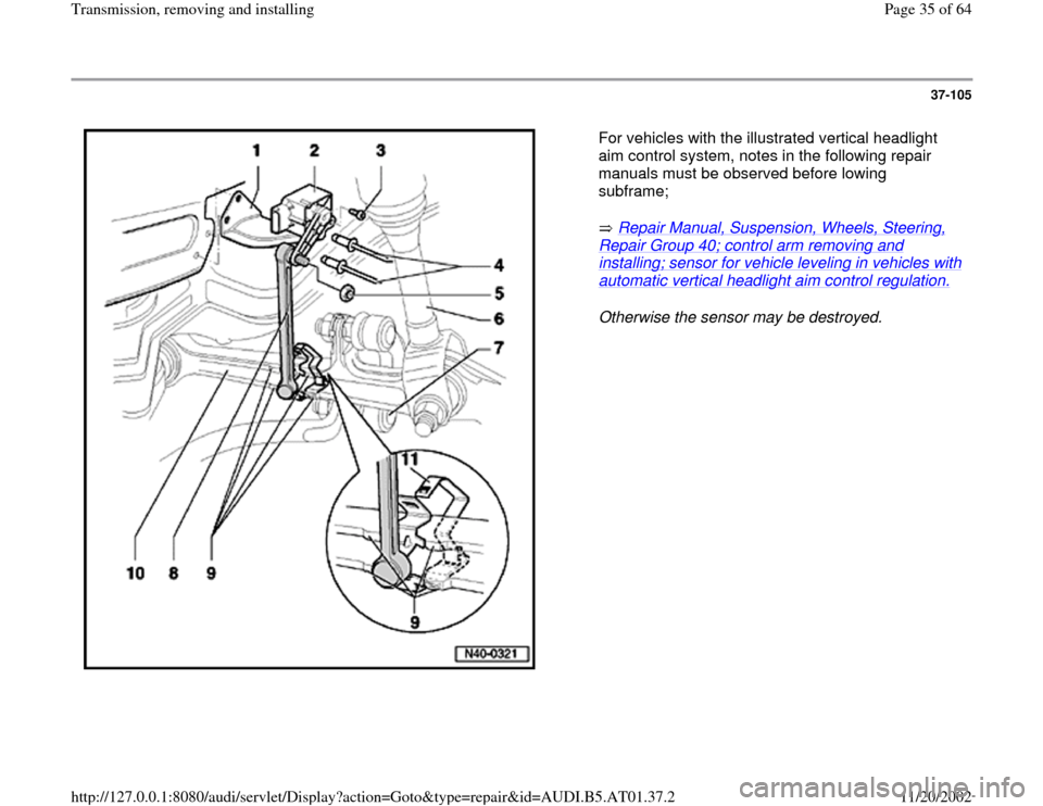
For vehicles with the illustrated vertical headlight
aim control system, notes in the following repair
manuals must be observed before lowing
subframe;
Repair Manual, Suspension, Wheels, Steering,
Repair Group 40; control arm removing and installing; sensor for vehicle leveling in vehicles with automatic vertical headlight aim control regulation.
Otherwise the sensor may be destroyed.
Pa
ge 35 of 64 Transmission, removin
g and installin
g
11/20/2002 htt
p://127.0.0.1:8080/audi/servlet/Dis
play?action=Goto&t
yp
e=re
pair&id=AUDI.B5.AT01.37.2
Page 50 of 64
37-119
Tightening torques
Notes:
Tightening torques are valid only for nuts and
bolts that are lightly greased, oiled, covered
with a thin coat of phosphate or blackened.
Other lubricants are permitted, e.g. engine oil or
transmission fluid, however they may not
contain graphite.
Do not use any degreased parts.
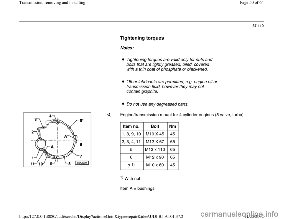
Engine/transmission mount for 4 cylinder engines (5 valve, turbo) 1) With nut
Item A = bushings Item no.
Bolt
Nm
1, 8, 9, 10 M10 X 45 45
2, 3, 4, 11 M12 X 67 65
5 M12 x 110 65
6 M12 x 90 65
7
1)
M10 x 60 45
Pa
ge 50 of 64 Transmission, removin
g and installin
g
11/20/2002 htt
p://127.0.0.1:8080/audi/servlet/Dis
play?action=Goto&t
yp
e=re
pair&id=AUDI.B5.AT01.37.2