fuel AUDI A8 2003 D3 / 2.G Technical Features Manual
[x] Cancel search | Manufacturer: AUDI, Model Year: 2003, Model line: A8, Model: AUDI A8 2003 D3 / 2.GPages: 96, PDF Size: 5.51 MB
Page 39 of 96

Downloaded from www.Manualslib.com manuals search engine 39
Advantages:
– Longer service life thanks to noncontacting
measurement system
– Protection against dirt and deposits
– Low contact currents
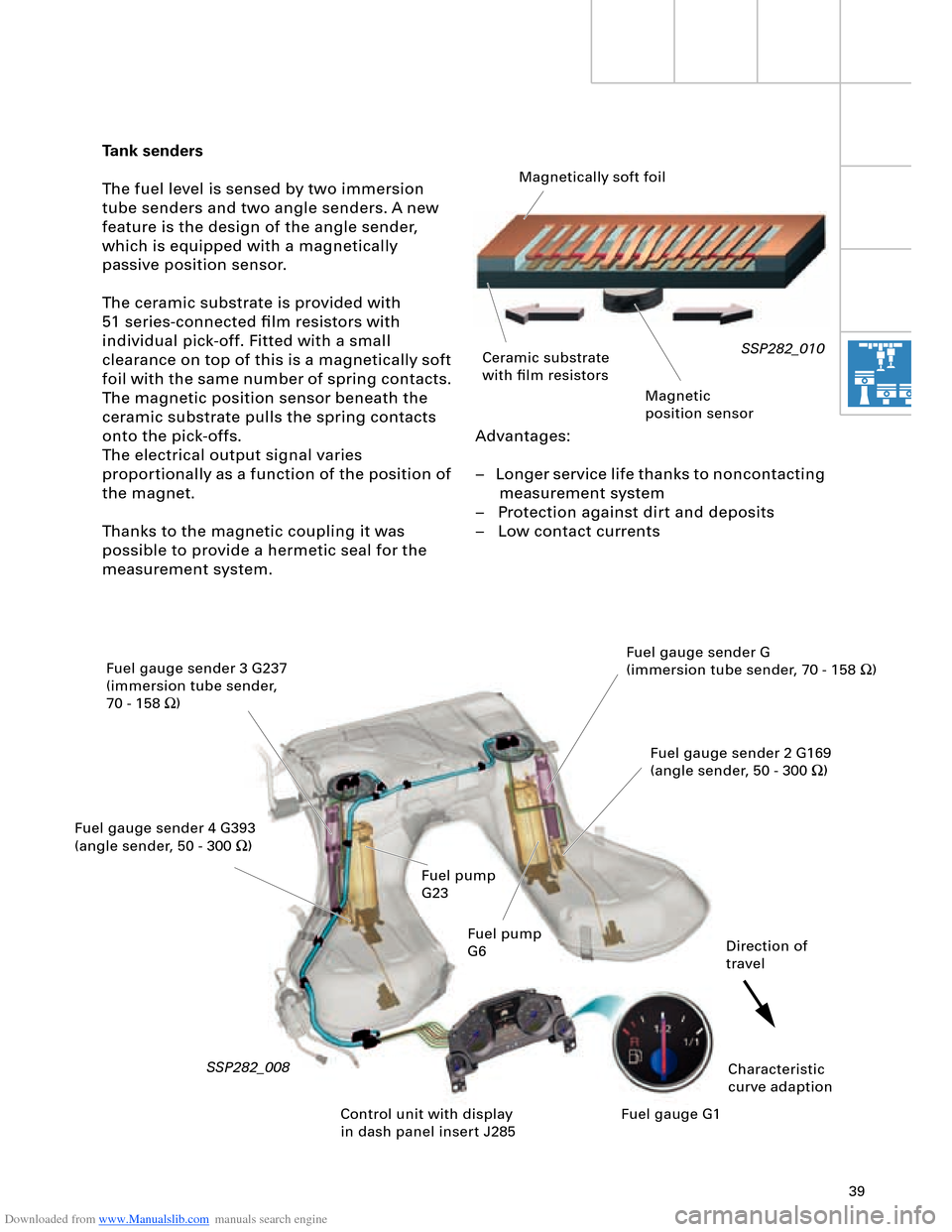
Tank senders
The fuel level is sensed by two immersion
tube senders and two angle senders. A new
feature is the design of the angle sender,
which is equipped with a magnetically
passive position sensor.
The ceramic substrate is provided with
51 series-connected film resistors with
individual pick-off. Fitted with a small
clearance on top of this is a magnetically soft
foil with the same number of spring contacts.
The magnetic position sensor beneath the
ceramic substrate pulls the spring contacts
onto the pick-offs.
The electrical output signal varies
proportionally as a function of the position of
the magnet.
Thanks to the magnetic coupling it was
possible to provide a hermetic seal for the
measurement system.
SSP282_010
SSP282_008
Magnetically soft foil
Ceramic substrate
with film resistors
Magnetic
position sensor
Fuel gauge sender 3 G237
(immersion tube sender,
70 - 158 W)
Fuel gauge sender 4 G393
(angle sender, 50 - 300 W)Fuel gauge sender G
(immersion tube sender, 70 - 158 W)
Fuel gauge sender 2 G169
(angle sender, 50 - 300 W)
Characteristic
curve adaption Direction of
travel
Control unit with display
in dash panel insert J285Fuel gauge G1 Fuel pump
G23
Fuel pump
G6
Page 40 of 96

Downloaded from www.Manualslib.com manuals search engine 40
Engine, Mechanics
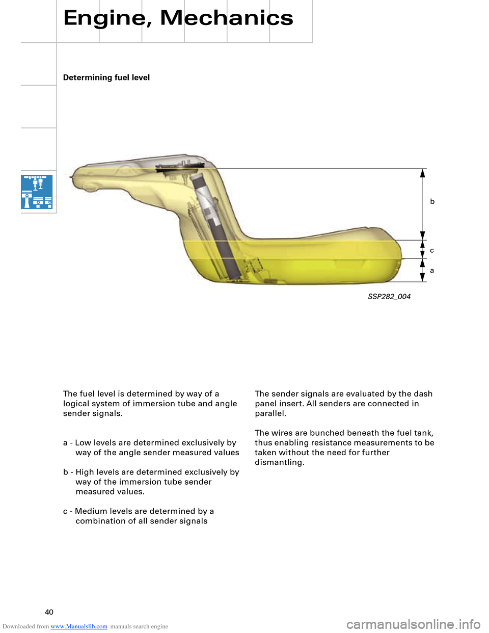
The fuel level is determined by way of a
logical system of immersion tube and angle
sender signals.
a - Low levels are determined exclusively by
way of the angle sender measured values
b - High levels are determined exclusively by
way of the immersion tube sender
measured values.
c - Medium levels are determined by a
combination of all sender signals
SSP282_004
The sender signals are evaluated by the dash
panel insert. All senders are connected in
parallel.
The wires are bunched beneath the fuel tank,
thus enabling resistance measurements to be
taken without the need for further
dismantling. Determining fuel level
a c b
Page 91 of 96

Downloaded from www.Manualslib.com manuals search engine 91
4.2 Auxiliary heating sequence
The level of fuel in the tank is
interrogated. If the fuel tank is "empty",
the auxiliary heating function is not
permitted and the auxiliary heater symbol
in the dash panel insert goes out. "Empty"
roughly corresponds to the red display
zone. The energy management control
unit J644 checks whether there is
sufficient energy to accept auxiliary
heating. If this is the case, the auxiliary
heater is switched on in the various
operating modes depending on the
characteristic temperature curve and the
fresh-air blower is actuated.
If the auxiliary heating temperature
reaches a level of 30 °C, the fresh-air
blower is activated and the coolant
shutoff valve N279 pulsed in line with the
characteristic curve.
The auxiliary heater is switched off
automatically on completion of the operating
time transmitted by the MMI system to the
Climatronic control unit or it can be switched
off using the remote control OFF button.
Auxiliary heater circulation pump control
To speed up heating of the passenger
compartment and to achieve a better "heat
yield" in the air conditioner unit heat
exchanger, the circulation pump V55 and
coolant shutoff valve N279 are pulsed as a
function of water temperature and the
heating circuit flow rate is thus reduced.
An electric circulation pump is used for the
auxiliary heater. It is not possible to reduce
the supply voltage in the auxiliary heater
control unit and the circulation pump is thus
actuated at specific intervals to decrease its
output.
Additional control curve for "auxiliary heater"
and "additional heater"
When the engine is on, the auxiliary heater
and engine temperatures are constantly
compared. A switch to the large coolant
circuit is made as soon as the engine
temperature exceeds the auxiliary heater
temperature.
Activation of auxiliary heater circulation
pump with engine on
(pulsed operation of circulation pump)
In order to be able to ensure a sufficient flow
of water through the heat exchanger, the
auxiliary heater circulation pump must
additionally be switched on, as is the case for
instance with the 12-cylinder engine.If the engine is switched off again and not
all additional heater criteria (temperature,
time) are satisfied, the auxiliary heater
remains in operation for any residual
operating time before being deactivated.
This function can be encoded.