clutch AUDI A8 2003 D3 / 2.G Technical Features Manual
[x] Cancel search | Manufacturer: AUDI, Model Year: 2003, Model line: A8, Model: AUDI A8 2003 D3 / 2.GPages: 96, PDF Size: 5.51 MB
Page 30 of 96
Downloaded from www.Manualslib.com manuals search engine 30
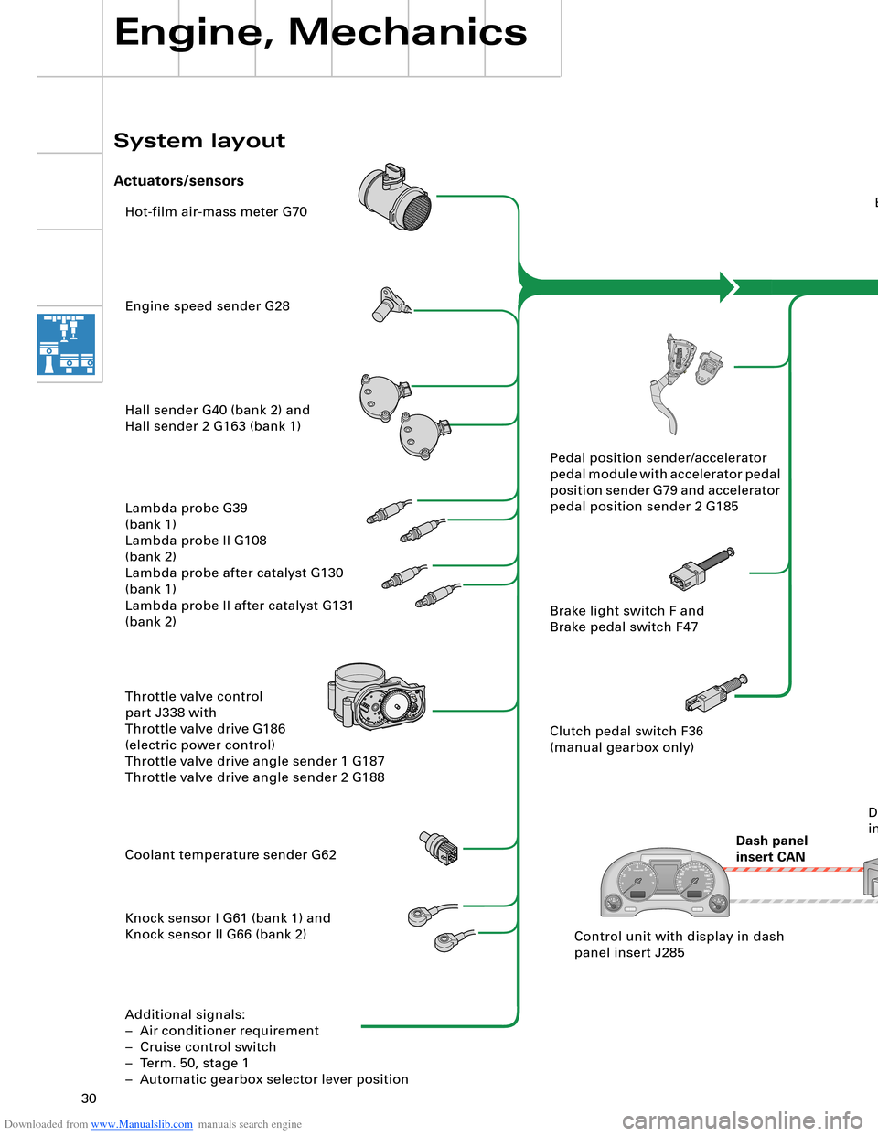
Hot-film air-mass meter G70
Engine speed sender G28
Hall sender G40 (bank 2) and
Hall sender 2 G163 (bank 1)
Lambda probe G39
(bank 1)
Lambda probe II G108
(bank 2)
Lambda probe after catalyst G130
(bank 1)
Lambda probe II after catalyst G131
(bank 2)
Throttle valve control
part J338 with
Throttle valve drive G186
(electric power control)
Throttle valve drive angle sender 1 G187
Throttle valve drive angle sender 2 G188
Coolant temperature sender G62
Knock sensor I G61 (bank 1) and
Knock sensor II G66 (bank 2)
Additional signals:
– Air conditioner requirement
– Cruise control switch
– Term. 50, stage 1
– Automatic gearbox selector lever positionEngine control unit J623
Steering
angle sender G85
ESP
control unit J104
Dash panel
insert CANAutomatic
gearbox
control unit J217
Airbag
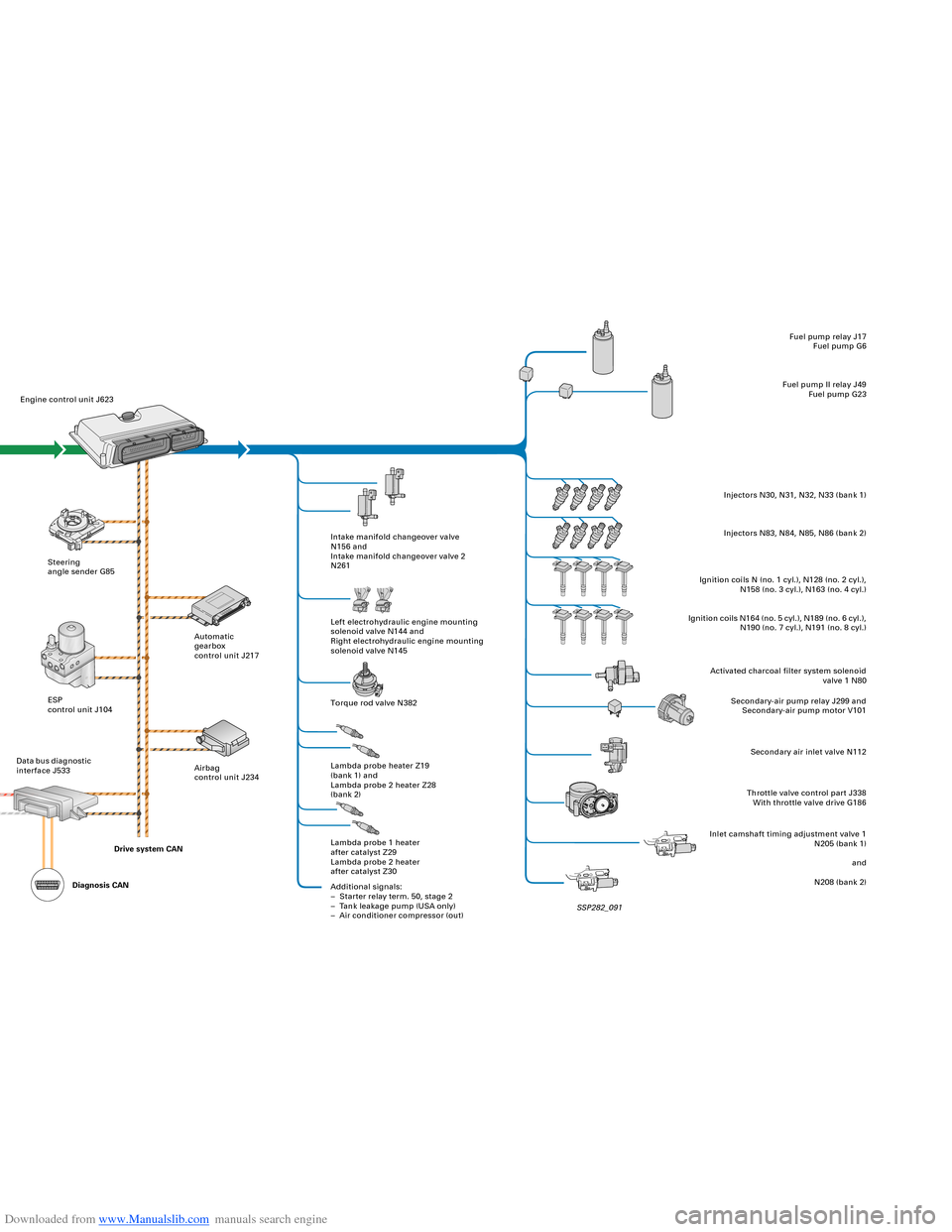
control unit J234Intake manifold changeover valve
N156 and
Intake manifold changeover valve 2
N261
Left electrohydraulic engine mounting
solenoid valve N144 and
Right electrohydraulic engine mounting
solenoid valve N145
Torque rod valve N382
Lambda probe heater Z19
(bank 1) and
Lambda probe 2 heater Z28
(bank 2)
Lambda probe 1 heater
after catalyst Z29
Lambda probe 2 heater
after catalyst Z30
Additional signals:
– Starter relay term. 50, stage 2
– Tank leakage pump (USA only)
– Air conditioner compressor (out)Fuel pump relay J17
Fuel pump G6
Fuel pump II relay J49
Fuel pump G23
Injectors N30, N31, N32, N33 (bank 1)
Injectors N83, N84, N85, N86 (bank 2)
Ignition coils N (no. 1 cyl.), N128 (no. 2 cyl.),
N158 (no. 3 cyl.), N163 (no. 4 cyl.)
Ignition coils N164 (no. 5 cyl.), N189 (no. 6 cyl.),
N190 (no. 7 cyl.), N191 (no. 8 cyl.)
Activated charcoal filter system solenoid
valve 1 N80
Secondary-air pump relay J299 and
Secondary-air pump motor V101
Secondary air inlet valve N112
Throttle valve control part J338
With throttle valve drive G186
Inlet camshaft timing adjustment valve 1
N205 (bank 1)
and
N208 (bank 2) Pedal position sender/accelerator
pedal module with accelerator pedal
position sender G79 and accelerator
pedal position sender 2 G185
Brake light switch F and
Brake pedal switch F47
Clutch pedal switch F36
(manual gearbox only)
Control unit with display in dash
panel insert J285Data bus diagnostic
interface J533
Engine, Mechanics
System layout
Actuators/sensors
SSP282_091 Drive system CAN
Diagnosis CAN
Page 31 of 96
Downloaded from www.Manualslib.com manuals search engine 30
Hot-film air-mass meter G70
Engine speed sender G28
Hall sender G40 (bank 2) and
Hall sender 2 G163 (bank 1)
Lambda probe G39
(bank 1)
Lambda probe II G108
(bank 2)
Lambda probe after catalyst G130
(bank 1)
Lambda probe II after catalyst G131
(bank 2)
Throttle valve control
part J338 with
Throttle valve drive G186
(electric power control)
Throttle valve drive angle sender 1 G187
Throttle valve drive angle sender 2 G188
Coolant temperature sender G62
Knock sensor I G61 (bank 1) and
Knock sensor II G66 (bank 2)
Additional signals:
– Air conditioner requirement
– Cruise control switch
– Term. 50, stage 1
– Automatic gearbox selector lever positionEngine control unit J623
Steering
angle sender G85
ESP
control unit J104
Dash panel
insert CANAutomatic
gearbox
control unit J217
Airbag
control unit J234Intake manifold changeover valve
N156 and
Intake manifold changeover valve 2
N261
Left electrohydraulic engine mounting
solenoid valve N144 and
Right electrohydraulic engine mounting
solenoid valve N145
Torque rod valve N382
Lambda probe heater Z19
(bank 1) and
Lambda probe 2 heater Z28
(bank 2)
Lambda probe 1 heater
after catalyst Z29
Lambda probe 2 heater
after catalyst Z30
Additional signals:
– Starter relay term. 50, stage 2
– Tank leakage pump (USA only)
– Air conditioner compressor (out)Fuel pump relay J17
Fuel pump G6
Fuel pump II relay J49
Fuel pump G23
Injectors N30, N31, N32, N33 (bank 1)
Injectors N83, N84, N85, N86 (bank 2)
Ignition coils N (no. 1 cyl.), N128 (no. 2 cyl.),
N158 (no. 3 cyl.), N163 (no. 4 cyl.)
Ignition coils N164 (no. 5 cyl.), N189 (no. 6 cyl.),
N190 (no. 7 cyl.), N191 (no. 8 cyl.)
Activated charcoal filter system solenoid
valve 1 N80
Secondary-air pump relay J299 and
Secondary-air pump motor V101
Secondary air inlet valve N112
Throttle valve control part J338
With throttle valve drive G186
Inlet camshaft timing adjustment valve 1
N205 (bank 1)
and
N208 (bank 2) Pedal position sender/accelerator
pedal module with accelerator pedal
position sender G79 and accelerator
pedal position sender 2 G185
Brake light switch F and
Brake pedal switch F47
Clutch pedal switch F36
(manual gearbox only)
Control unit with display in dash
panel insert J285Data bus diagnostic
interface J533
Engine, Mechanics
System layout
Actuators/sensors
SSP282_091 Drive system CAN
Diagnosis CAN
Page 41 of 96
Downloaded from www.Manualslib.com manuals search engine 41
Automatically controlled
starting
The automatic start control is integrated into
the engine control unit.
A new feature is that starter control is no
longer implemented by way of the ignition/
starter switch D (switching of terminal 50),
but rather it is performed automatically by
the engine control unit.
Release for starter actuation is always
transmitted by the entry and start
authorisation control unit J518 to the engine
control unit J623.
In addition to general release by the
immobilizer, the following start release
conditions also have to be satisfied:
– Start signal from entry and start
authorisation switch E415 or entry and
start authorisation button E408
– Clutch pedal pressed, signal from clutch
pedal switch F194 (manual gearbox only)
– Selector lever position P or N (automatic
gearbox control unit J217)
– In the event of start signal via entry and
start authorisation button E408, brake
must be pressed (signal from brake light
switch F via separate interface)
As a safeguard, P/N signal or signal from
clutch pedal switch F194 must be applied
to the separate interfaces of the two
control units (J623 and J518).
Additional safeguard, as entry and start
authorisation button E408 can be
actuated by front passenger.
1
2 1
1
2
Page 42 of 96
Downloaded from www.Manualslib.com manuals search engine 42
Engine, Mechanics
Sequence of operations
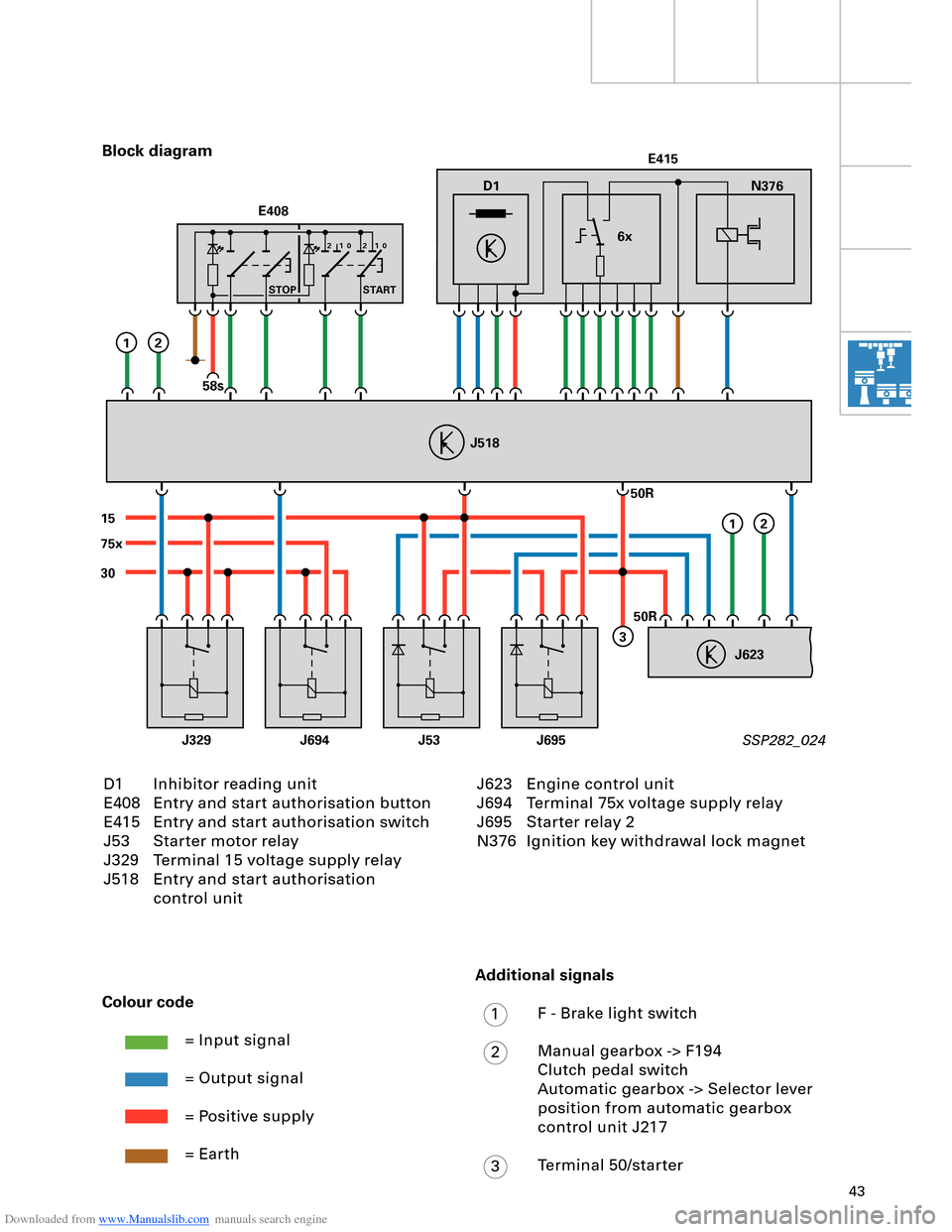
1 Entry and start authorisation switch E415/entry and start authorisation button E408
2 Entry and start authorisation control unit J518
The entry and start authorisation control
unit checks for authorisation – in the form
of information on selector slide position N
or P – from the automatic gearbox control
unit J217 and for brake application in the
case of a start signal from the entry and
start authorisation button E408.
3 Engine control unit J623 Application of selector slide position P/N or
"clutch pressed" information to the engine
control unit (separate interface) causes the
two starter relays J53 and J695 to be
actuated simultaneously. The relays then
switch terminal 50 for starter actuation.
The starter operates and cranks the engine.
On exceeding a defined engine speed, the
engine control unit J623 recognises that
the engine has started and the relays are
deenergised (thus terminating starting
process).
As a safeguard, two relays are connected in
series. In the event of fusion welding of the
make contacts (relay remains closed
following deenergisation), the engine
control unit J623 can thus interrupt the
circuit (terminal 50) by way of the other
relay in each case.
The two relays are deenergised alternately
in order to ensure even make contact wear
(break spark) in both relays. The
deenergisation sequence alternates. The driver triggers a brief start signal
(min. 20 ms) by turning the ignition key to
start position or by pressing the entry and
start authorisation button E408.
If the start prerequisites have been
satisfied, the entry and start authorisation
control unit J518 transmits a start request
– terminal 50 ON – to the engine control
unit J623.
The entry and start authorisation control unit J518 also controls the terminal 15 and
terminal 75x circuits.
Relay operation is monitored and faults diagnosed by evaluating the alternating
deenergisation with the aid of the terminal
50R interface.
The terminal 50R interface represents a link
with terminal 50 and provides the engine
control unit J623 with feedback for start
control/diagnosis.
Automatically controlled starting is not
permitted in the event of undervoltage or a
system fault.
The engine can however be started
manually by way of corresponding start
signal actuation.
To relieve the load on the starter and
battery, the relay actuation time is
limited to approx. 10 seconds per starting
operation (automatic or manual starting).
Page 43 of 96
Downloaded from www.Manualslib.com manuals search engine 43
D1
30
15
J329J53J695J694
75xE415
N376
6x
J623
J518
50R
50R
3
12
12
E408
STOP START
58s
210 210
D1 Inhibitor reading unit
E408 Entry and start authorisation button
E415 Entry and start authorisation switch
J53 Starter motor relay
J329 Terminal 15 voltage supply relay
J518 Entry and start authorisation
control unit Block diagram
SSP282_024
Colour code
= Input signal
= Output signal
= Positive supply
= Earth
J623 Engine control unit
J694 Terminal 75x voltage supply relay
J695 Starter relay 2
N376 Ignition key withdrawal lock magnet
Additional signals
F - Brake light switch
Manual gearbox -> F194
Clutch pedal switch
Automatic gearbox -> Selector lever
position from automatic gearbox
control unit J217
Terminal 50/starter
1
2
3
Page 45 of 96
Downloaded from www.Manualslib.com manuals search engine 45
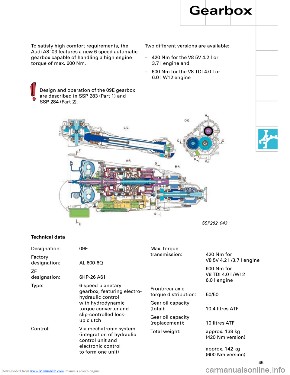
Two different versions are available:
– 420 Nm for the V8 5V 4.2 l or
3.7 l engine and
– 600 Nm for the V8 TDI 4.0 l or
6.0 l W12 engine To satisfy high comfort requirements, the
Audi A8 ´03 features a new 6-speed automatic
gearbox capable of handling a high engine
torque of max. 600 Nm.
Gearbox
Design and operation of the 09E gearbox
are described in SSP 283 (Part 1) and
SSP 284 (Part 2).
SSP282_043
Technical data
Designation: 09E
Factory
designation: AL 600-6Q
ZF
designation: 6HP-26 A61
Type: 6-speed planetary
gearbox, featuring electro-
hydraulic control
with hydrodynamic
torque converter and
slip-controlled lock-
up clutch
Control: Via mechatronic system
(integration of hydraulic
control unit and
electronic control
to form one unit)Max. torque
transmission: 420 Nm for
V8 5V 4.2 l /3.7 l engine
600 Nm for
V8 TDI 4.0 l /W12
6.0 l engine
Front/rear axle
torque distribution: 50/50
Gear oil capacity
(total): 10.4 litres ATF
Gear oil capacity
(replacement): 10 litres ATF
Total weight: approx. 138 kg
(420 Nm version)
approx. 142 kg
(600 Nm version)