Downloaded from www.Manualslib.com manuals search engine 27
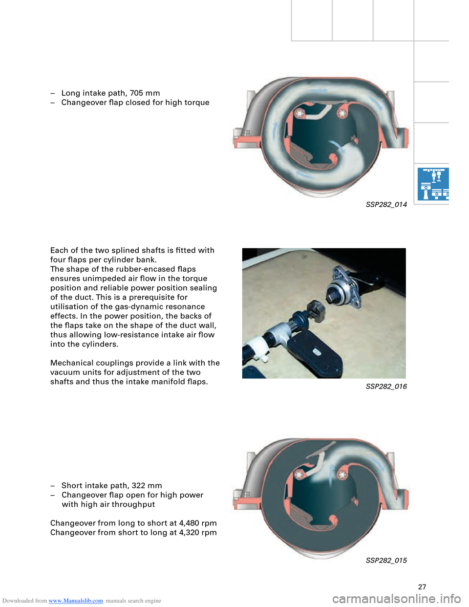
– Long intake path, 705 mm
– Changeover flap closed for high torque
Each of the two splined shafts is fitted with
four flaps per cylinder bank.
The shape of the rubber-encased flaps
ensures unimpeded air flow in the torque
position and reliable power position sealing
of the duct. This is a prerequisite for
utilisation of the gas-dynamic resonance
effects. In the power position, the backs of
the flaps take on the shape of the duct wall,
thus allowing low-resistance intake air flow
into the cylinders.
Mechanical couplings provide a link with the
vacuum units for adjustment of the two
shafts and thus the intake manifold flaps.
– Short intake path, 322 mm
– Changeover flap open for high power
with high air throughput
Changeover from long to short at 4,480 rpm
Changeover from short to long at 4,320 rpm
SSP282_014
SSP282_016
SSP282_015
Downloaded from www.Manualslib.com manuals search engine 28
Engine, Mechanics
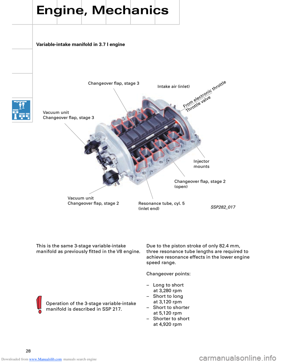
Variable-intake manifold in 3.7 l engine
Operation of the 3-stage variable-intake
manifold is described in SSP 217.
SSP282_017
This is the same 3-stage variable-intake
manifold as previously fitted in the V8 engine.Due to the piston stroke of only 82.4 mm,
three resonance tube lengths are required to
achieve resonance effects in the lower engine
speed range.
Changeover points:
– Long to short
at 3,280 rpm
– Short to long
at 3,120 rpm
– Short to shorter
at 5,120 rpm
– Shorter to short
at 4,920 rpm
Changeover flap, stage 3
From electronic throttle
Throttle valve
Intake air (inlet)
Changeover flap, stage 2
(open)
Resonance tube, cyl. 5
(inlet end) Vacuum unit
Changeover flap, stage 2 Vacuum unit
Changeover flap, stage 3
Injector
mounts

