module AUDI A8 2003 D3 / 2.G Technical Features Manual
[x] Cancel search | Manufacturer: AUDI, Model Year: 2003, Model line: A8, Model: AUDI A8 2003 D3 / 2.GPages: 96, PDF Size: 5.51 MB
Page 30 of 96
Downloaded from www.Manualslib.com manuals search engine 30
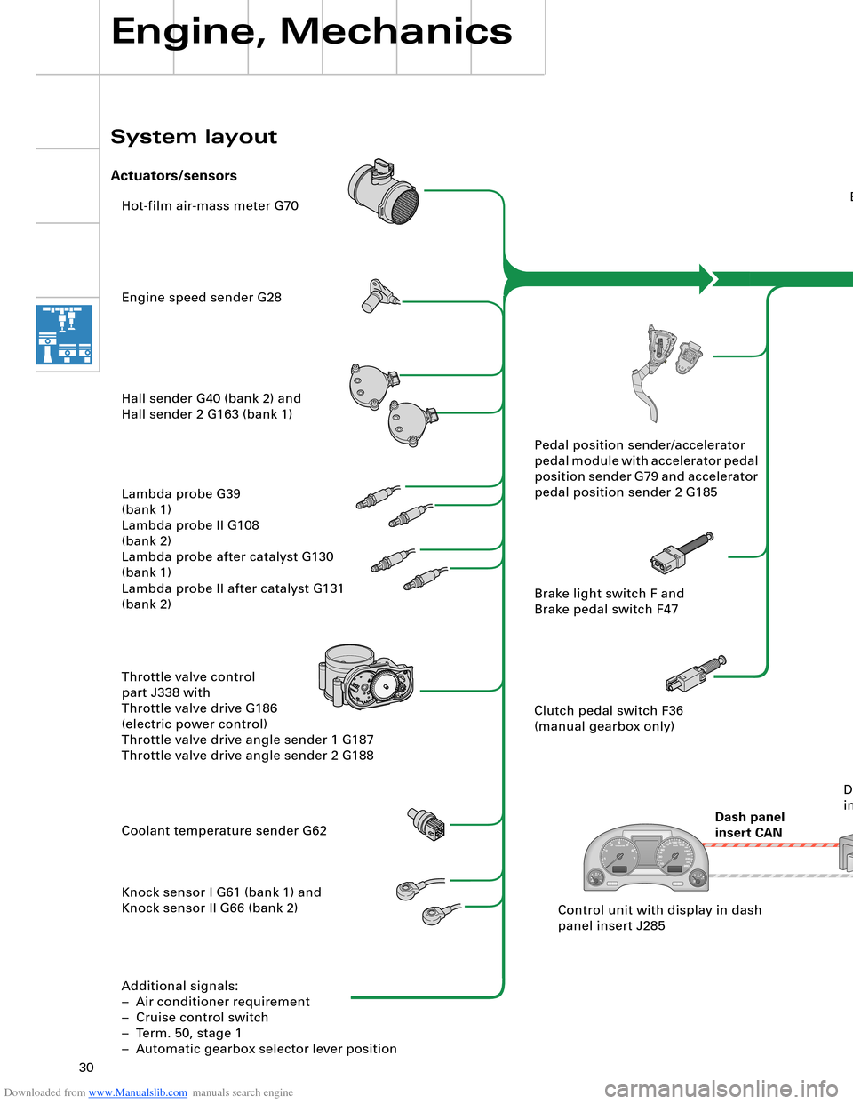
Hot-film air-mass meter G70
Engine speed sender G28
Hall sender G40 (bank 2) and
Hall sender 2 G163 (bank 1)
Lambda probe G39
(bank 1)
Lambda probe II G108
(bank 2)
Lambda probe after catalyst G130
(bank 1)
Lambda probe II after catalyst G131
(bank 2)
Throttle valve control
part J338 with
Throttle valve drive G186
(electric power control)
Throttle valve drive angle sender 1 G187
Throttle valve drive angle sender 2 G188
Coolant temperature sender G62
Knock sensor I G61 (bank 1) and
Knock sensor II G66 (bank 2)
Additional signals:
– Air conditioner requirement
– Cruise control switch
– Term. 50, stage 1
– Automatic gearbox selector lever positionEngine control unit J623
Steering
angle sender G85
ESP
control unit J104
Dash panel
insert CANAutomatic
gearbox
control unit J217
Airbag
control unit J234Intake manifold changeover valve
N156 and
Intake manifold changeover valve 2
N261
Left electrohydraulic engine mounting
solenoid valve N144 and
Right electrohydraulic engine mounting
solenoid valve N145
Torque rod valve N382
Lambda probe heater Z19
(bank 1) and
Lambda probe 2 heater Z28
(bank 2)
Lambda probe 1 heater
after catalyst Z29
Lambda probe 2 heater
after catalyst Z30
Additional signals:
– Starter relay term. 50, stage 2
– Tank leakage pump (USA only)
– Air conditioner compressor (out)Fuel pump relay J17
Fuel pump G6
Fuel pump II relay J49
Fuel pump G23
Injectors N30, N31, N32, N33 (bank 1)
Injectors N83, N84, N85, N86 (bank 2)
Ignition coils N (no. 1 cyl.), N128 (no. 2 cyl.),
N158 (no. 3 cyl.), N163 (no. 4 cyl.)
Ignition coils N164 (no. 5 cyl.), N189 (no. 6 cyl.),
N190 (no. 7 cyl.), N191 (no. 8 cyl.)
Activated charcoal filter system solenoid
valve 1 N80
Secondary-air pump relay J299 and
Secondary-air pump motor V101
Secondary air inlet valve N112
Throttle valve control part J338
With throttle valve drive G186
Inlet camshaft timing adjustment valve 1
N205 (bank 1)
and
N208 (bank 2) Pedal position sender/accelerator
pedal module with accelerator pedal
position sender G79 and accelerator
pedal position sender 2 G185
Brake light switch F and
Brake pedal switch F47
Clutch pedal switch F36
(manual gearbox only)
Control unit with display in dash
panel insert J285Data bus diagnostic
interface J533
Engine, Mechanics
System layout
Actuators/sensors
SSP282_091 Drive system CAN
Diagnosis CAN
Page 31 of 96
Downloaded from www.Manualslib.com manuals search engine 30
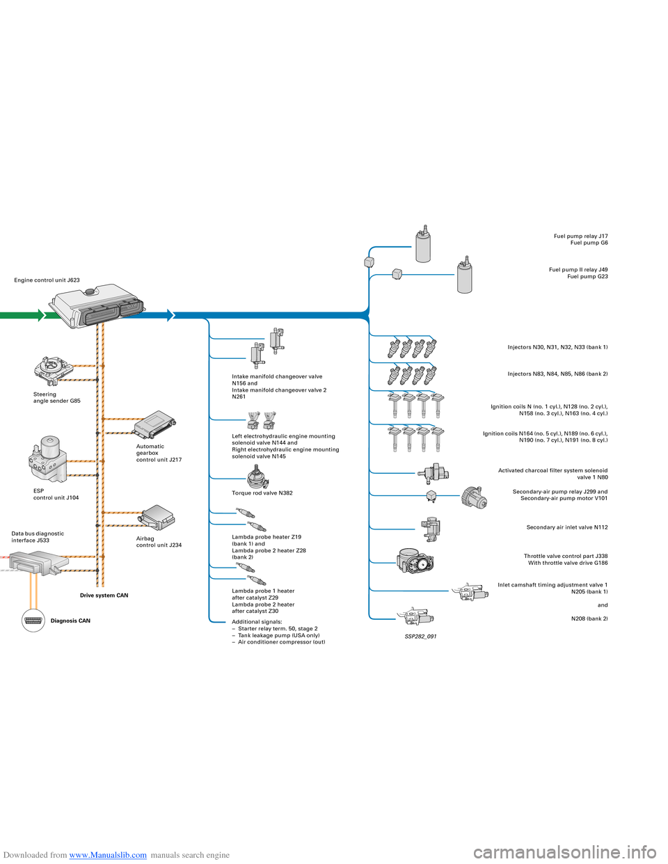
Hot-film air-mass meter G70
Engine speed sender G28
Hall sender G40 (bank 2) and
Hall sender 2 G163 (bank 1)
Lambda probe G39
(bank 1)
Lambda probe II G108
(bank 2)
Lambda probe after catalyst G130
(bank 1)
Lambda probe II after catalyst G131
(bank 2)
Throttle valve control
part J338 with
Throttle valve drive G186
(electric power control)
Throttle valve drive angle sender 1 G187
Throttle valve drive angle sender 2 G188
Coolant temperature sender G62
Knock sensor I G61 (bank 1) and
Knock sensor II G66 (bank 2)
Additional signals:
– Air conditioner requirement
– Cruise control switch
– Term. 50, stage 1
– Automatic gearbox selector lever positionEngine control unit J623
Steering
angle sender G85
ESP
control unit J104
Dash panel
insert CANAutomatic
gearbox
control unit J217
Airbag
control unit J234Intake manifold changeover valve
N156 and
Intake manifold changeover valve 2
N261
Left electrohydraulic engine mounting
solenoid valve N144 and
Right electrohydraulic engine mounting
solenoid valve N145
Torque rod valve N382
Lambda probe heater Z19
(bank 1) and
Lambda probe 2 heater Z28
(bank 2)
Lambda probe 1 heater
after catalyst Z29
Lambda probe 2 heater
after catalyst Z30
Additional signals:
– Starter relay term. 50, stage 2
– Tank leakage pump (USA only)
– Air conditioner compressor (out)Fuel pump relay J17
Fuel pump G6
Fuel pump II relay J49
Fuel pump G23
Injectors N30, N31, N32, N33 (bank 1)
Injectors N83, N84, N85, N86 (bank 2)
Ignition coils N (no. 1 cyl.), N128 (no. 2 cyl.),
N158 (no. 3 cyl.), N163 (no. 4 cyl.)
Ignition coils N164 (no. 5 cyl.), N189 (no. 6 cyl.),
N190 (no. 7 cyl.), N191 (no. 8 cyl.)
Activated charcoal filter system solenoid
valve 1 N80
Secondary-air pump relay J299 and
Secondary-air pump motor V101
Secondary air inlet valve N112
Throttle valve control part J338
With throttle valve drive G186
Inlet camshaft timing adjustment valve 1
N205 (bank 1)
and
N208 (bank 2) Pedal position sender/accelerator
pedal module with accelerator pedal
position sender G79 and accelerator
pedal position sender 2 G185
Brake light switch F and
Brake pedal switch F47
Clutch pedal switch F36
(manual gearbox only)
Control unit with display in dash
panel insert J285Data bus diagnostic
interface J533
Engine, Mechanics
System layout
Actuators/sensors
SSP282_091 Drive system CAN
Diagnosis CAN
Page 59 of 96
Downloaded from www.Manualslib.com manuals search engine 59SSP282_063
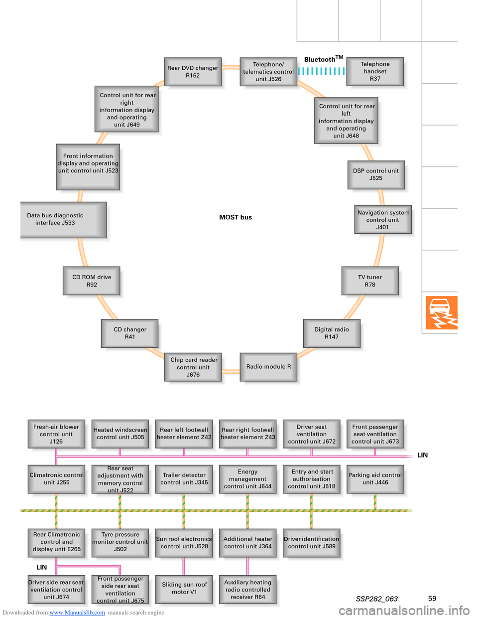
Telephone/
telematics control
unit J526
Front information
display and operating
unit control unit J523Rear DVD changer
R162Telephone
handset
R37
Control unit for rear
left
information display
and operating
unit J648
DSP control unit
J525
Navigation system
control unit
J401
TV tuner
R78
Digital radio
R147
Radio module R Chip card reader
control unit
J676 CD changer
R41 CD ROM drive
R92 Data bus diagnostic
interface J533
Fresh-air blower
control unit
J126Heated windscreen
control unit J505Rear left footwell
heater element Z42Rear right footwell
heater element Z43Driver seat
ventilation
control unit J672Front passenger
seat ventilation
control unit J673
Parking aid control
unit J446 Entry and start
authorisation
control unit J518 Energy
management
control unit J644 Rear seat
adjustment with
memory control
unit J522 Climatronic control
unit J255
Trailer detector
control unit J345
Rear Climatronic
control and
display unit E265Tyre pressure
monitor control unit
J502
Sun roof electronics
control unit J528
Additional heater
control unit J364Driver identification
control unit J589
Auxiliary heating
radio controlled
receiver R64 Sliding sun roof
motor V1 Front passenger
side rear seat
ventilation
control unit J675 Driver side rear seat
ventilation control
unit J674 Control unit for rear
right
information display
and operating
unit J649
MOST busBluetooth
TM
LIN
LIN
Page 63 of 96
Downloaded from www.Manualslib.com manuals search engine 63
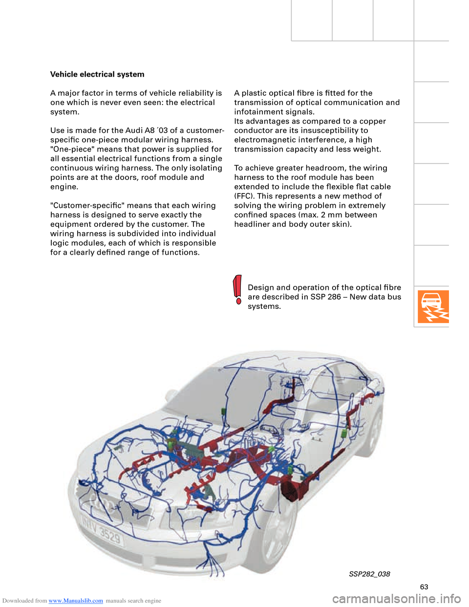
Vehicle electrical system
A major factor in terms of vehicle reliability is
one which is never even seen: the electrical
system.
Use is made for the Audi A8 ´03 of a customer-
specific one-piece modular wiring harness.
"One-piece" means that power is supplied for
all essential electrical functions from a single
continuous wiring harness. The only isolating
points are at the doors, roof module and
engine.
"Customer-specific" means that each wiring
harness is designed to serve exactly the
equipment ordered by the customer. The
wiring harness is subdivided into individual
logic modules, each of which is responsible
for a clearly defined range of functions.
SSP282_038
Design and operation of the optical fibre
are described in SSP 286 – New data bus
systems. A plastic optical fibre is fitted for the
transmission of optical communication and
infotainment signals.
Its advantages as compared to a copper
conductor are its insusceptibility to
electromagnetic interference, a high
transmission capacity and less weight.
To achieve greater headroom, the wiring
harness to the roof module has been
extended to include the flexible flat cable
(FFC). This represents a new method of
solving the wiring problem in extremely
confined spaces (max. 2 mm between
headliner and body outer skin).
Page 68 of 96
Downloaded from www.Manualslib.com manuals search engine 68
Electrical System
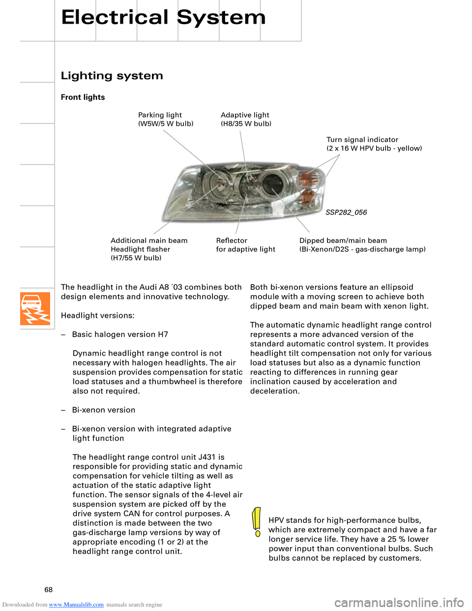
The headlight in the Audi A8 ´03 combines both
design elements and innovative technology.
Headlight versions:
– Basic halogen version H7
Dynamic headlight range control is not
necessary with halogen headlights. The air
suspension provides compensation for static
load statuses and a thumbwheel is therefore
also not required.
– Bi-xenon version
– Bi-xenon version with integrated adaptive
light function
The headlight range control unit J431 is
responsible for providing static and dynamic
compensation for vehicle tilting as well as
actuation of the static adaptive light
function. The sensor signals of the 4-level air
suspension system are picked off by the
drive system CAN for control purposes. A
distinction is made between the two
gas-discharge lamp versions by way of
appropriate encoding (1 or 2) at the
headlight range control unit.
Lighting system
Front lights
SSP282_056
HPV stands for high-performance bulbs,
which are extremely compact and have a far
longer service life. They have a 25 % lower
power input than conventional bulbs. Such
bulbs cannot be replaced by customers.
Both bi-xenon versions feature an ellipsoid
module with a moving screen to achieve both
dipped beam and main beam with xenon light.
The automatic dynamic headlight range control
represents a more advanced version of the
standard automatic control system. It provides
headlight tilt compensation not only for various
load statuses but also as a dynamic function
reacting to differences in running gear
inclination caused by acceleration and
deceleration.
Dipped beam/main beam
(Bi-Xenon/D2S - gas-discharge lamp)Turn signal indicator
(2 x 16 W HPV bulb - yellow) Parking light
(W5W/5 W bulb)Adaptive light
(H8/35 W bulb)
Additional main beam
Headlight flasher
(H7/55 W bulb)Reflector
for adaptive light