wheel AUDI A8 2003 D3 / 2.G Technical Features Manual
[x] Cancel search | Manufacturer: AUDI, Model Year: 2003, Model line: A8, Model: AUDI A8 2003 D3 / 2.GPages: 96, PDF Size: 5.51 MB
Page 18 of 96
Downloaded from www.Manualslib.com manuals search engine 18
Safety systems
2-stage front airbags
The 2-stage triggering of the front airbags
provides optimum restraint in crash
situations at around 30 km/h. There is a
separate firing pellet for each stage in the
driver's and front passenger's airbag. These
ignite successively at specified time intervals.
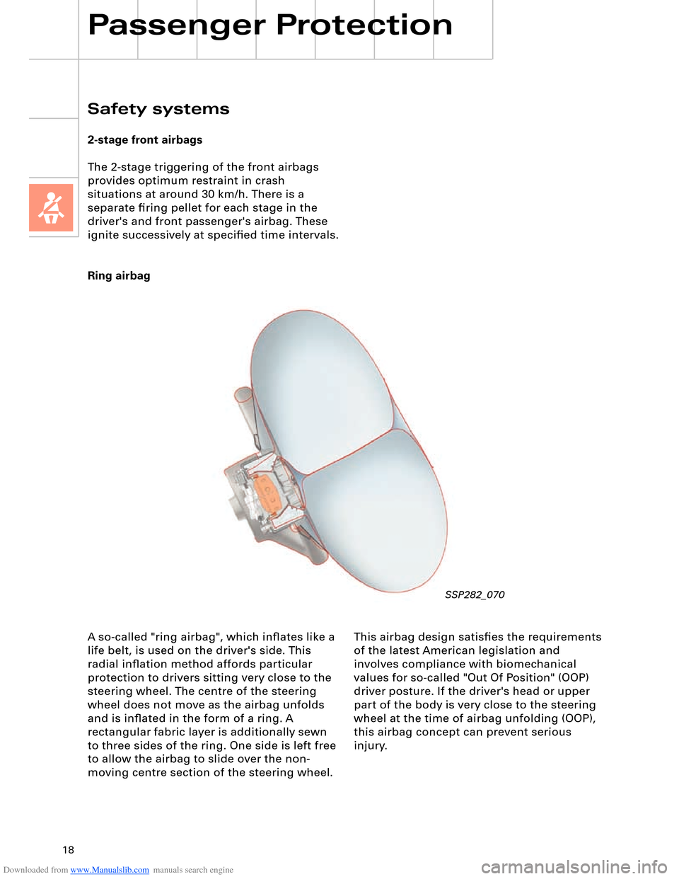
Ring airbag
Passenger Protection
SSP282_070
A so-called "ring airbag", which inflates like a
life belt, is used on the driver's side. This
radial inflation method affords particular
protection to drivers sitting very close to the
steering wheel. The centre of the steering
wheel does not move as the airbag unfolds
and is inflated in the form of a ring. A
rectangular fabric layer is additionally sewn
to three sides of the ring. One side is left free
to allow the airbag to slide over the non-
moving centre section of the steering wheel. This airbag design satisfies the requirements
of the latest American legislation and
involves compliance with biomechanical
values for so-called "Out Of Position" (OOP)
driver posture. If the driver's head or upper
part of the body is very close to the steering
wheel at the time of airbag unfolding (OOP),
this airbag concept can prevent serious
injury.
Page 49 of 96
Downloaded from www.Manualslib.com manuals search engine 49
All axle components are new on account of
the geometric and kinematic modifications as
compared to the predecessor model, the air
suspension and the weight reductions
achieved.
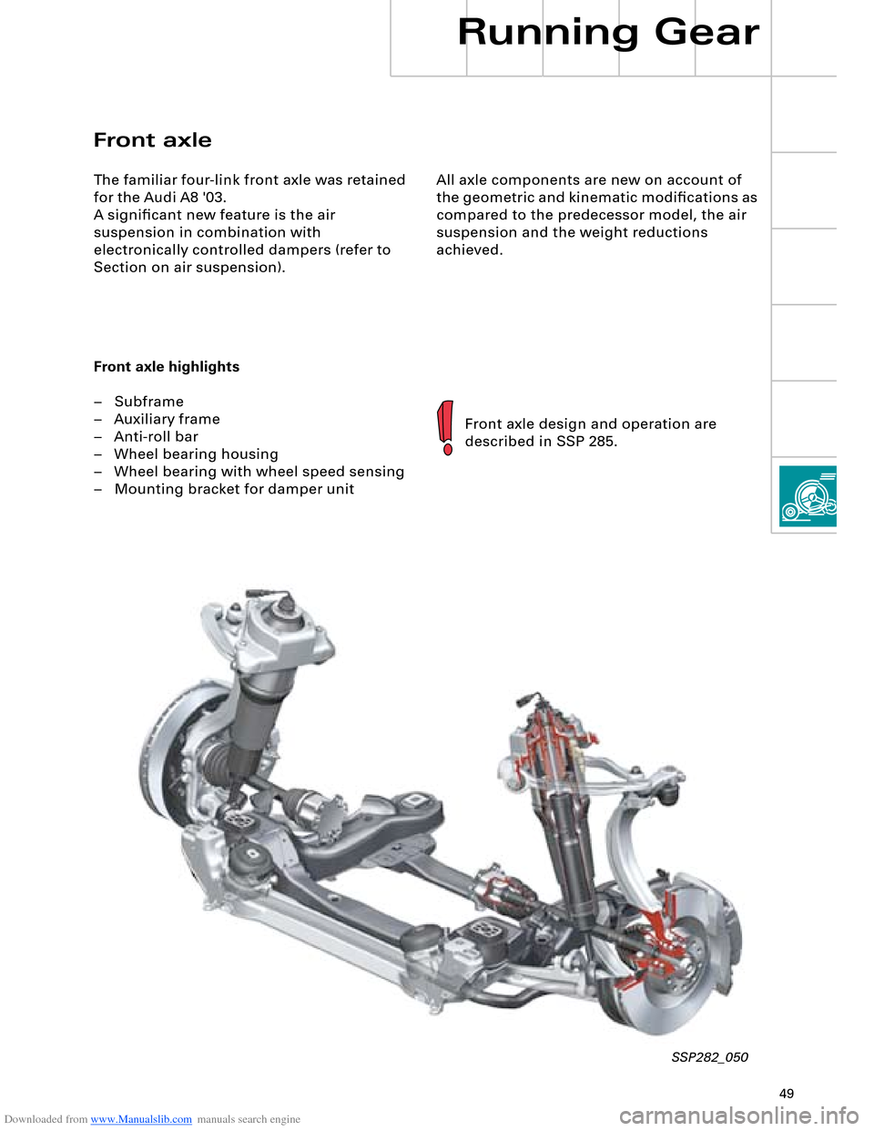
Front axle
The familiar four-link front axle was retained
for the Audi A8 '03.
A significant new feature is the air
suspension in combination with
electronically controlled dampers (refer to
Section on air suspension).
Front axle highlights
– Subframe
– Auxiliary frame
– Anti-roll bar
– Wheel bearing housing
– Wheel bearing with wheel speed sensing
– Mounting bracket for damper unit
Front axle design and operation are
described in SSP 285.
SSP282_050
Running Gear
Page 50 of 96
Downloaded from www.Manualslib.com manuals search engine 50
All axle components are new on account of
the geometric and kinematic modifications as
compared to the predecessor model, the air
suspension and the weight reductions
achieved.
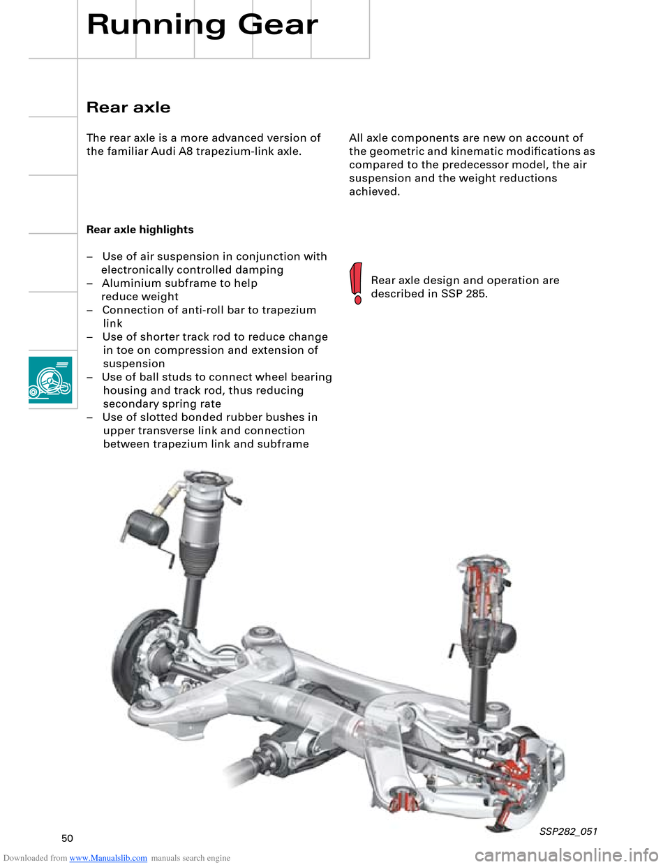
Rear axle highlights
– Use of air suspension in conjunction with
electronically controlled damping
– Aluminium subframe to help
reduce weight
– Connection of anti-roll bar to trapezium
link
– Use of shorter track rod to reduce change
in toe on compression and extension of
suspension
– Use of ball studs to connect wheel bearing
housing and track rod, thus reducing
secondary spring rate
– Use of slotted bonded rubber bushes in
upper transverse link and connection
between trapezium link and subframe
Rear axle design and operation are
described in SSP 285.
Rear axle
The rear axle is a more advanced version of
the familiar Audi A8 trapezium-link axle.
Running Gear
SSP282_051
Page 51 of 96
Downloaded from www.Manualslib.com manuals search engine 51
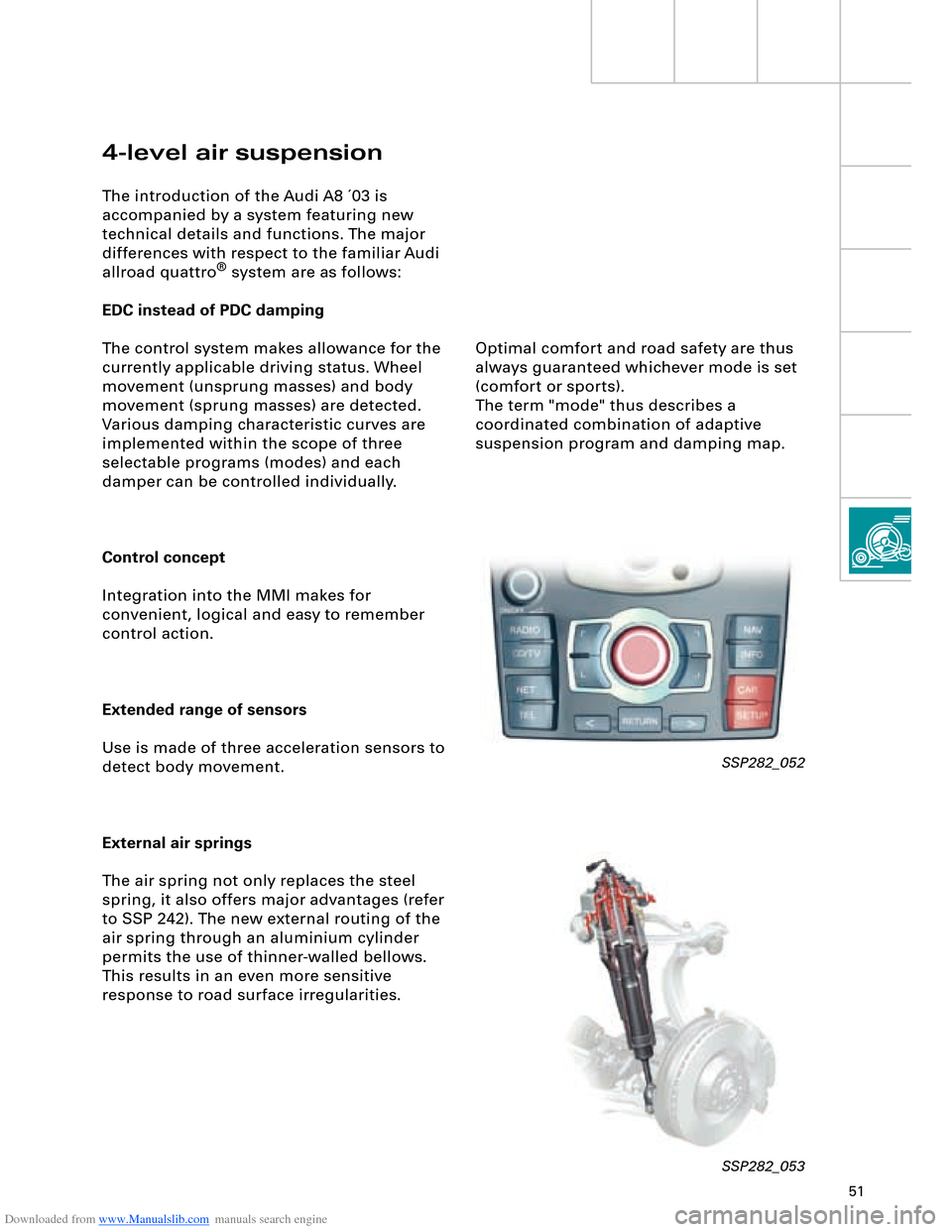
4-level air suspension
The introduction of the Audi A8 ´03 is
accompanied by a system featuring new
technical details and functions. The major
differences with respect to the familiar Audi
allroad quattro
® system are as follows:
EDC instead of PDC damping
The control system makes allowance for the
currently applicable driving status. Wheel
movement (unsprung masses) and body
movement (sprung masses) are detected.
Various damping characteristic curves are
implemented within the scope of three
selectable programs (modes) and each
damper can be controlled individually.
Control concept
Integration into the MMI makes for
convenient, logical and easy to remember
control action.
Extended range of sensors
Use is made of three acceleration sensors to
detect body movement.
External air springs
The air spring not only replaces the steel
spring, it also offers major advantages (refer
to SSP 242). The new external routing of the
air spring through an aluminium cylinder
permits the use of thinner-walled bellows.
This results in an even more sensitive
response to road surface irregularities.
SSP282_052
SSP282_053
Optimal comfort and road safety are thus
always guaranteed whichever mode is set
(comfort or sports).
The term "mode" thus describes a
coordinated combination of adaptive
suspension program and damping map.
Page 53 of 96
Downloaded from www.Manualslib.com manuals search engine 53
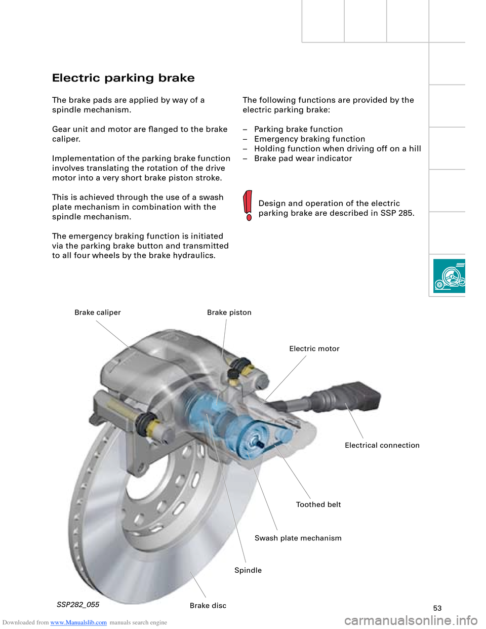
The following functions are provided by the
electric parking brake:
– Parking brake function
– Emergency braking function
– Holding function when driving off on a hill
– Brake pad wear indicator
Electric parking brake
The brake pads are applied by way of a
spindle mechanism.
Gear unit and motor are flanged to the brake
caliper.
Implementation of the parking brake function
involves translating the rotation of the drive
motor into a very short brake piston stroke.
This is achieved through the use of a swash
plate mechanism in combination with the
spindle mechanism.
The emergency braking function is initiated
via the parking brake button and transmitted
to all four wheels by the brake hydraulics.
Design and operation of the electric
parking brake are described in SSP 285.
SSP282_055
Toothed belt
Swash plate mechanismElectric motor Brake piston
SpindleElectrical connection
Brake disc Brake caliper
Page 58 of 96
Downloaded from www.Manualslib.com manuals search engine 58
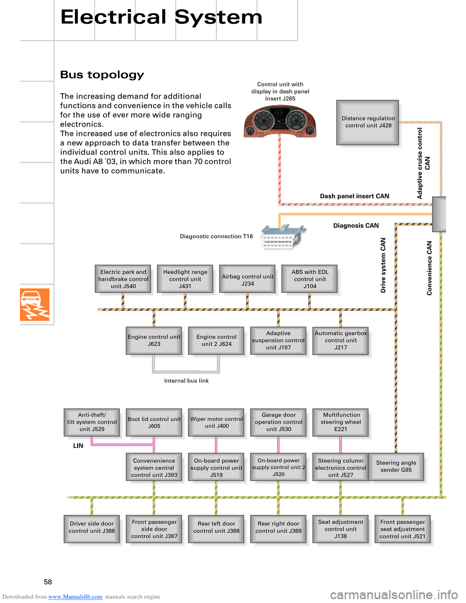
Bus topology
Electrical System
The increasing demand for additional
functions and convenience in the vehicle calls
for the use of ever more wide ranging
electronics.
The increased use of electronics also requires
a new approach to data transfer between the
individual control units. This also applies to
the Audi A8 ´03, in which more than 70 control
units have to communicate.
Distance regulation
control unit J428
Electric park and
handbrake control
unit J540Headlight range
control unit
J431Airbag control unit
J234ABS with EDL
control unit
J104
Engine control unit
J623Adaptive
suspension control
unit J197 Engine control
unit 2 J624Automatic gearbox
control unit
J217
Anti-theft/
tilt system control
unit J529
Boot lid control unit
J605Wiper motor control
unit J400Garage door
operation control
unit J530 Multifunction
steering wheel
E221
Convenenience
system central
control unit J393On-board power
supply control unit
J519
On-board power
supply control unit 2
J520Steering column
electronics control
unit J527Steering angle
sender G85
Driver side door
control unit J386Front passenger
side door
control unit J387Rear left door
control unit J388Rear right door
control unit J389Seat adjustment
control unit
J136Front passenger
seat adjustment
control unit J521 Control unit with
display in dash panel
insert J285
Diagnostic connection T16
Dash panel insert CAN
Drive system CAN
Diagnosis CAN
Convenience CAN
Internal bus link
LIN
Adaptive cruise control
CAN
Page 65 of 96
Downloaded from www.Manualslib.com manuals search engine 65
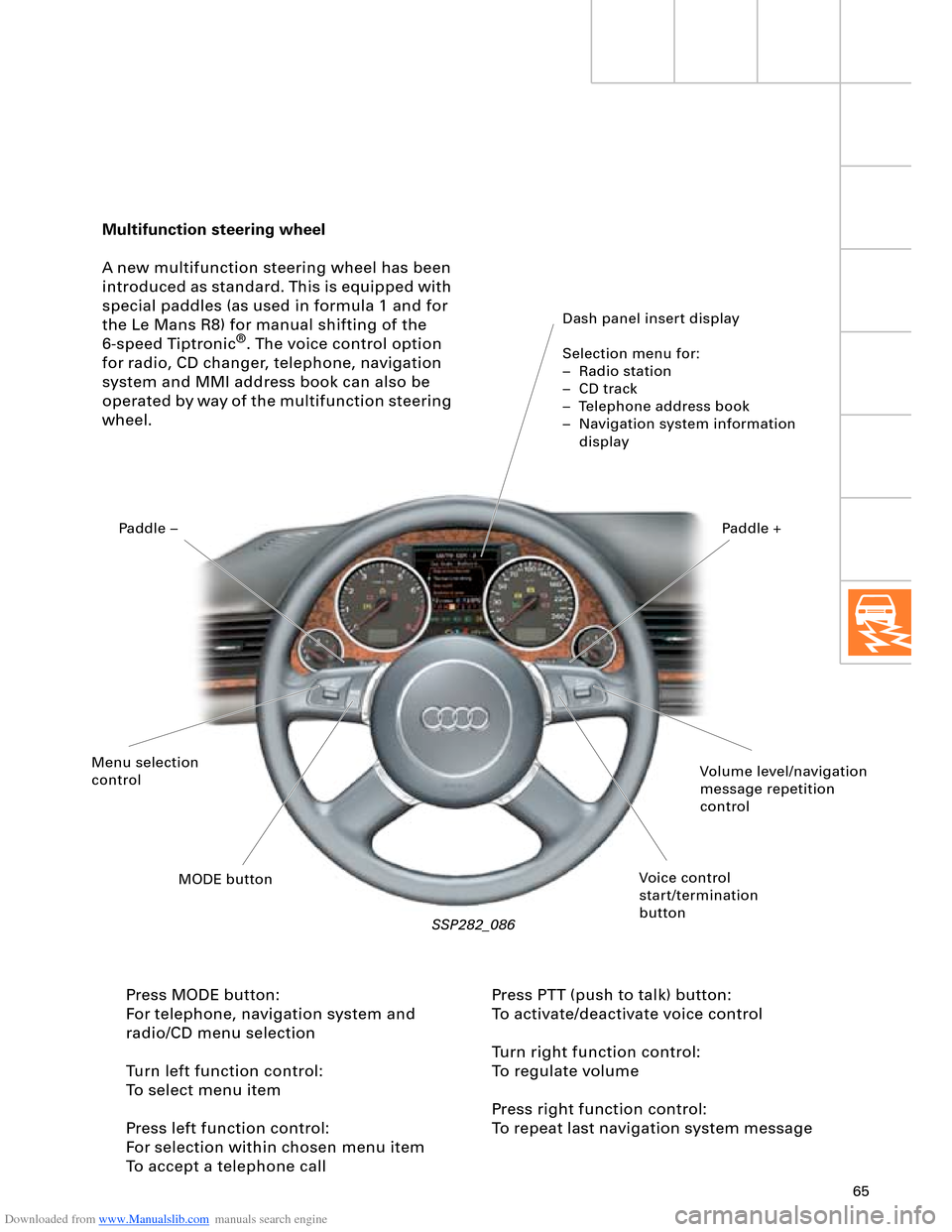
Multifunction steering wheel
A new multifunction steering wheel has been
introduced as standard. This is equipped with
special paddles (as used in formula 1 and for
the Le Mans R8) for manual shifting of the
6-speed Tiptronic
®. The voice control option
for radio, CD changer, telephone, navigation
system and MMI address book can also be
operated by way of the multifunction steering
wheel.
Dash panel insert display
Selection menu for:
– Radio station
– CD track
– Telephone address book
– Navigation system information
display
SSP282_086
Press MODE button:
For telephone, navigation system and
radio/CD menu selection
Turn left function control:
To select menu item
Press left function control:
For selection within chosen menu item
To accept a telephone callPress PTT (push to talk) button:
To activate/deactivate voice control
Turn right function control:
To regulate volume
Press right function control:
To repeat last navigation system message
Volume level/navigation
message repetition
control
Voice control
start/termination
button MODE button Menu selection
controlPaddle –Paddle +
Page 68 of 96
Downloaded from www.Manualslib.com manuals search engine 68
Electrical System
The headlight in the Audi A8 ´03 combines both
design elements and innovative technology.
Headlight versions:
– Basic halogen version H7
Dynamic headlight range control is not
necessary with halogen headlights. The air
suspension provides compensation for static
load statuses and a thumbwheel is therefore
also not required.
– Bi-xenon version
– Bi-xenon version with integrated adaptive
light function
The headlight range control unit J431 is
responsible for providing static and dynamic
compensation for vehicle tilting as well as
actuation of the static adaptive light
function. The sensor signals of the 4-level air
suspension system are picked off by the
drive system CAN for control purposes. A
distinction is made between the two
gas-discharge lamp versions by way of
appropriate encoding (1 or 2) at the
headlight range control unit.
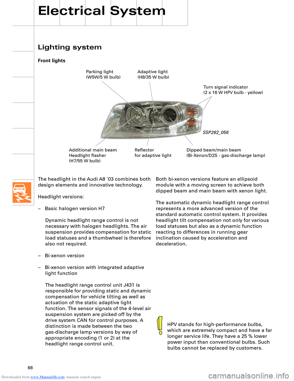
Lighting system
Front lights
SSP282_056
HPV stands for high-performance bulbs,
which are extremely compact and have a far
longer service life. They have a 25 % lower
power input than conventional bulbs. Such
bulbs cannot be replaced by customers.
Both bi-xenon versions feature an ellipsoid
module with a moving screen to achieve both
dipped beam and main beam with xenon light.
The automatic dynamic headlight range control
represents a more advanced version of the
standard automatic control system. It provides
headlight tilt compensation not only for various
load statuses but also as a dynamic function
reacting to differences in running gear
inclination caused by acceleration and
deceleration.
Dipped beam/main beam
(Bi-Xenon/D2S - gas-discharge lamp)Turn signal indicator
(2 x 16 W HPV bulb - yellow) Parking light
(W5W/5 W bulb)Adaptive light
(H8/35 W bulb)
Additional main beam
Headlight flasher
(H7/55 W bulb)Reflector
for adaptive light