service indicator AUDI A8 2014 Owners Manual
[x] Cancel search | Manufacturer: AUDI, Model Year: 2014, Model line: A8, Model: AUDI A8 2014Pages: 314, PDF Size: 78.47 MB
Page 19 of 314
Instruments and warning/indicator lights 17
Seek professional assistance if the battery
charge leve l is too low.
(•) Low battery charge: battery will be
c harged while driving
If the indicator light turns on and the mes
sage appears, there may be limited start ing
ability.
If th is message turns off after a little wh ile,
the battery charged enough wh ile driving .
If the message does not turn off, have your
author ized Audi dealer or qualified workshop
correct the malfunction.
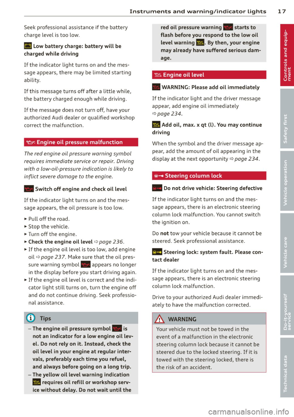
~ Engine oil pressure malfunction
The red engine oil pressure warning symbol
requires immediate service or repair . Driving
with a low-oil-pressure indication is likely to
inflict severe damage to the engine.
• Switch off engine and check oil level
If the indicator light turns on and the mes
sage appears, the oil pressure is too low.
.. Pull off the road.
.. Stop the vehicle .
.. Turn off the engine.
.,. Check the engine oil level¢ page 236 .
.. If the engine oil level is too low, add engine
o il ¢
page 237 . Make sure that the oil pres
sure warning symbol. appears no longer
in the d isplay before you start driving again.
.,. If the engine oil level is correct and the indi
cator light st ill turns on, turn the engine off
and do not continue driving. Seek professio
nal assistance.
(D Tips
- The engine oil pressure symbol. is
not an indicator for a low engine oil lev
el. Do not rely on it. Instead, check the
oil level in your engine at regular inter·
vals, preferably each time you refuel,
and always before going on a long trip.
- The yellow oil level warning indication
Ill requires oil refill or workshop serv
ice without delay. Do not wait until the red oil pressure
warning. starts to
flash before you respond to the low oil
level warning
II. By then, your engine
may already have suffered serious dam
age.
~"' Engine oil level
• WARNING : Please add oil immediately
If the indicator light and the driver message
appear, add engine o il immed iately
¢ page 234.
II Add oil, max . x qt (l). You may continue
driving
When the symbol and the driver message ap
pear, add the amount of oil appearing in the
display at the next opportunity ¢
page 234.
@-Steering column lock
• Do not drive vehicle: Steering defective
If the indicator light turns on and the mes
sage appears, there is an e lectronic steering
column lock malfunction. You cannot switch
the ignit ion on .
Do
not tow your vehicle because it cannot be
steered. Seek professiona l assistance .
!'II Steering lock: system fault. Please con
tact deale r
If the indicator light turns on and the mes
sage appears, there is an e lectronic stee ring
column lock malfunction.
Drive to your authorized Audi dealer immedi
ate ly to have the malfunction corrected .
A WARNING
Your vehicle must not be towed in the
event of a malfunction in the elec tron ic
steering column lock because it cannot be
steered due to the locked steering . If it is
towed with the steering locked, there is
the r isk of an accident.
Page 20 of 314
18 Instruments and warning/indicator lights
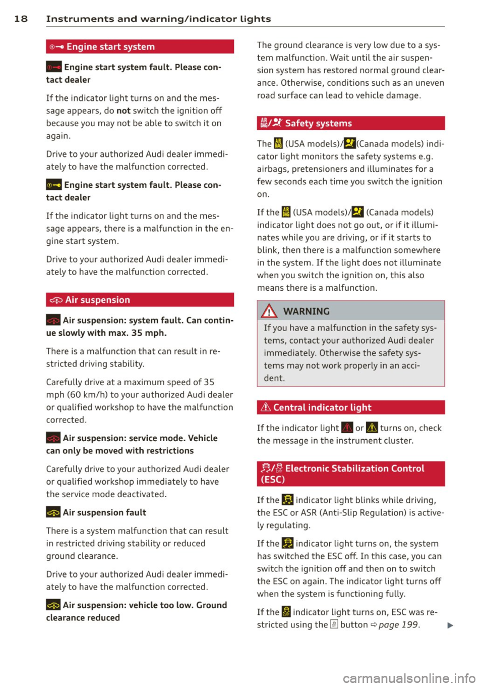
©-Engine start system
• Engine start sy stem fault. Please con
tact dealer
If t h e in dicator light turns on and the mes
sage appears, do
not sw itch the ignition off
be cause you may not be able to switch it on
aga in .
D rive to you r autho rized Aud i deale r immedi
ate ly to hav e th e malfunction corrected.
11111 Engine start system fault. Please con
tact dealer
If the indicator light t urns on and the mes
sage appears, there is a ma lfunction in the en
g ine start system.
D rive to yo ur autho rize d Au di dea le r immedi
ate ly to have t he mal function cor rected .
0 Air suspension
• Air suspension: system fault. Can cont in
ue slowly with max. 35 mph .
There is a malfunctio n that can res ult in re
stricted dr iving stability.
Ca re fully d rive a t a maxim um s peed o f 35
mph ( 60 km/h) to your author ized A udi dealer
or qua lified wor kshop to have the malfunction
corrected.
• Air suspension: service mode. Vehicle
can only be moved with restrictions
Ca re fully drive to your au thori zed A udi d ealer
or quali fied wor kshop immedi ate ly to have
the servi ce mode deac tiva ted.
l!IJ Air suspension fault
There is a system ma lfunction that can result
in restr icted dr iving stability or red uced
g ro und cleara nce.
Drive to yo ur authorized Aud i dealer immedi
ately to have t he malfunction corrected .
l!IJ Air suspension: vehicle too low. Ground
clearance reduced
T he groun d clearance is very low due to a sys
tem malfunction. Wa it until the air suspen
s io n system has resto red no rma l ground clear
ance. Ot herwise, cond it ions such as an uneven
road surface can lead to vehicle damage.
tli1!.t Safety systems
T he fl (U SA models)/ El(Canada models) indi
cator lig ht monitors the safety sys tems e .g.
airbags , p retens ione rs and illuminates fo r a
f ew seco nds ea ch time y ou swit ch t he ign ition
o n .
If th e
I (USA mod els)/ EI (Can ada models)
i ndica to r li ght does no t go o ut, or if it illum i
n at es while yo u are d riving, o r if it start s to
blink, the n t here is a m alf u nctio n somewhe re
in the sys tem . If the ligh t does no t illumina te
whe n you switch the ig nitio n on, t his also
means there is a mal funct ion .
A WARNING ....._
If yo u have a ma lf u nction in t he safety sys
tems, contact you r auth orized Audi dea le r
immedia tely. Othe rwise t he safety sys
t ems may not work properly i n an acc i
d en t.
~ Central indicator light
If th e indicato r light . or D tur ns o n, check
th e m essage in th e i nstru men t cluster.
F!,J [}; Electronic Stabilization Control
(ESC)
If the bl indicator light b links w hile d riving,
the ESC or AS R (Anti-Slip Re gulation) is active
ly reg ulating.
If the
bl indicator light turns on , th e system
has switc hed the ESC off . In t his case, yo u can
switch the ign ition off and then on to switch
the ESC o n aga in. The ind icator lig ht tu rns off
whe n the system is functioni ng fu lly.
If the
fl indicato r light turns on, ESC was re-
stricted using the
[!I button ¢ page 199. ..,.
Page 24 of 314
22 Instruments and warning/indicator lights
If the symbol illuminates, add windshield
washer fluid to the washer system/headlight
washer system* ¢
page 247.
~ Windshield wipers
g,.5 Windshield wiper defective
There is a malfunction with the windshield
wipers.
Drive to your authorized Audi dealer immedi
ately to have the malfunction corrected.
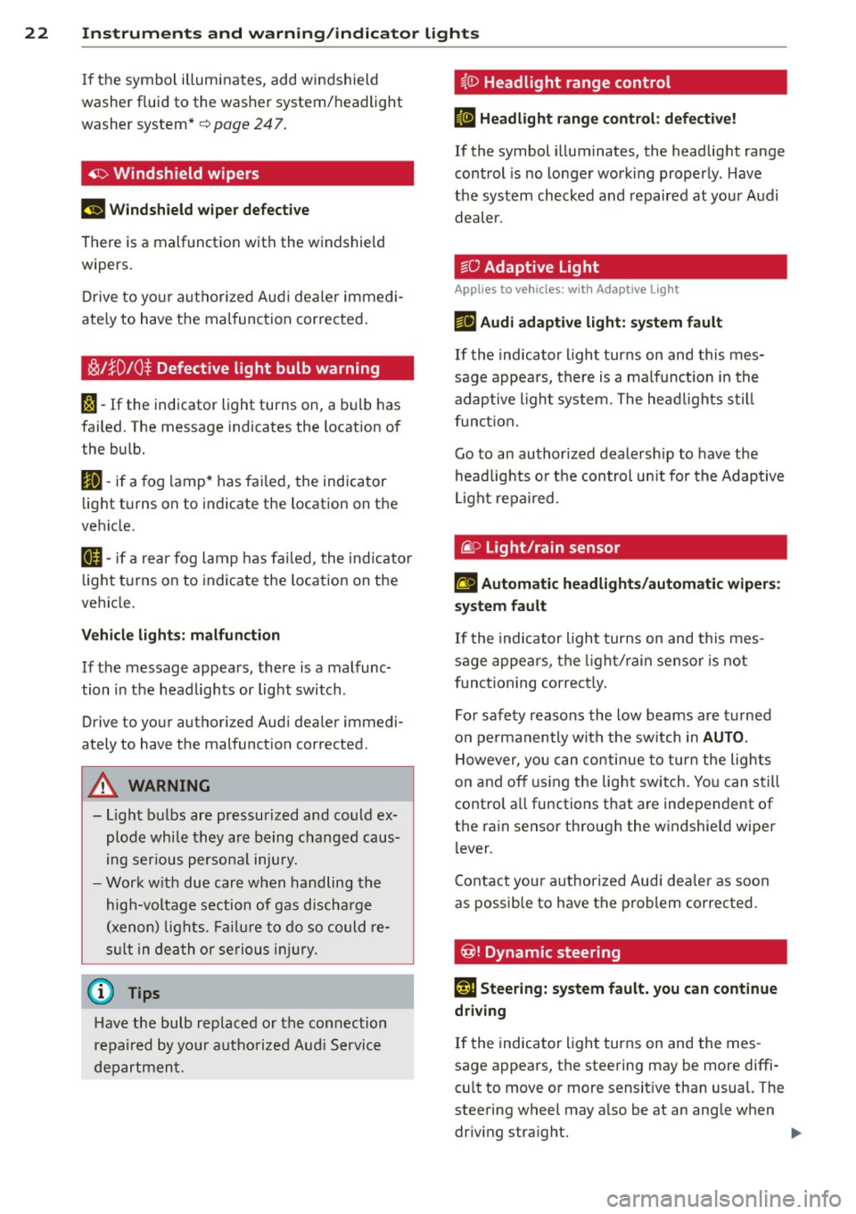
i§i l}D 10 $ Defective light bulb warning
I-If the indicator light turns on, a bulb has
failed. The message indicates the location of
the bulb.
II-if a fog lamp* has failed, the indicator
light turns on to indicate the location on the
vehicle.
a-if a rear fog lamp has failed, the indicator
light turns on to indicate the location on the
vehicle.
Vehicle lights: malfunction
If the message appears, there is a malfunc
tion in the headlights or light switch .
Drive to your authorized Audi dealer immedi
ately to have the malfunction corrected.
A WARNING
, -
- Light bulbs are pressurized and could ex-
plode while they are being changed caus
ing serious personal injury.
- Work with due care when handling the
high-voltage section of gas discharge
(xenon) lights. Failure to do so could re
sult in death or serious injury.
Have the bulb replaced or the connection
repaired by your authorized Audi Service
department.
~(D Headlight range control
II Headlight range control: defective!
If the symbol illuminates, the headlight range
control is no longer working properly. Have
the system checked and repaired at your Audi
dealer.
§0 Adaptive Light
Applies to veh icles: w ith Adapt ive light
m;J Audi adaptive light: system fault
If the indicator light turns on and this mes
sage appears, there is a malfunction in the
adaptive light system. The headlights still
function.
Go to an authorized dealership to have the
headlights or the control unit for the Adaptive
Light repaired.
@.D Light /rain sen sor
l;I Automatic headlights/automatic wipers:
system fault
If the indicator light turns on and this mes
sage appears, the light/rain sensor is not
functioning correctly.
For safety reasons the low beams are turned
on permanently with the switch in
AUTO.
However, you can continue to turn the lights
on and off using the light switch. You can still
control all functions that are independent of
the rain sensor through the windshield wiper
lever .
Contact your authorized Audi dealer as soon
as possible to have the problem corrected.
@! Dynamic steering
l:rj Steering: system fault. you can continue
driving
If the indicator light turns on and the mes
sage appears, the steering may be more diffi
cult to move or more sensitive than usual. The
steering wheel may also be at an angle when driving straight. .,..
Page 26 of 314
24 Instruments and warning/indicator lights
Driver information
display
Overview
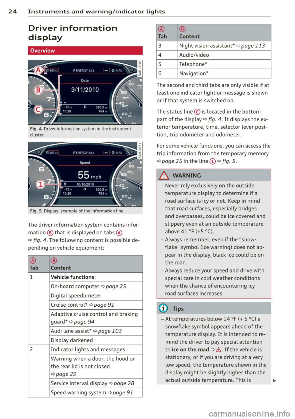
Fig. 4 Driver informat ion system in the instrument
cluster
Fig. S D isplay: example of th e informat ion line
The driver information system contains infor
mation @ that is displayed on tabs @
c:;, fig. 4. The following content is possible de
pending on vehicle equipment:
@
®
Tab Content
1 Vehicle functions :
On-board computer c::> page 25
Digital speedometer
Cruise control*
c:;, page 91
Adaptive cruise control and braking
guard*
c:;, page 94
Audi lane assist* c::> page 103
Display darkened
2 Indicator lights and messages
Warning when a door, the hood or the rear lid is not closed
c::>page29
Service interval display c::>page 28
Speed warning system ¢page 91
@ ®
Tab Content
3
Night vision assistant* c:;, page 113
4 Audio/video
s Telephone*
6 Navigation*
T he second and th ird tabs are only vis ible if at
least one indicator light or message is shown
or if that system is sw itched on.
The status line © is located in the bottom
part of the display
c::> fig. 4. It displays the ex
terior temperature , time, selector lever posi
t ion, trip odometer and odometer.
For some vehicle functions, you can access the
trip information from the temporary memory
c::> page 25 in the line (D c::> fig. 5.
_& WARNING ,___ -
- Never rely exclusively on the outside
temperature display to determine if a
road surface is icy or not. Keep in mind
that road surfaces, especially bridges
and overpasses, could be ice covered and
slippery even at an outside temperature
above 41 °F
(+5 °() .
- Always remember, even if the "snow
flake" symbol (ice warning) does not ap
pear in the d isplay, black ice could be on
the road .
- Always reduce your speed and drive with special care in cold weather cond itions
when the chance of encountering icy
road surfaces increases.
(D Tips
-At temperatures below 14 °F (+ 5 °C) a
snowf lake symbol appears ahead of the
temperature display. It is intended to re
m ind the driver to pay special attention
to
ice on the road c::> ,&. If the vehicle is
stationary, or if you are driving at a very
low speed, the temperature shown in the
display might be slightly higher than the
actual outs ide temperature. This is .,.
Page 30 of 314
28 Instruments and warning/indicator lights
The date and time are shown in the instru
ment cluster d isplay
c:;, page 24, fig. 4. There
is also an ana log clock in the center console
c:;, fig. 12.
When you open the driver's door, the date and
time appear in the instrument cluster display
for 30 seconds . When the ign ition is switched
on, the time is always displayed in the status
line © regardless of the current display.
You can set the time on both clocks and the date display in the MMI. Refer to the MMI
owner's manual for instructions.
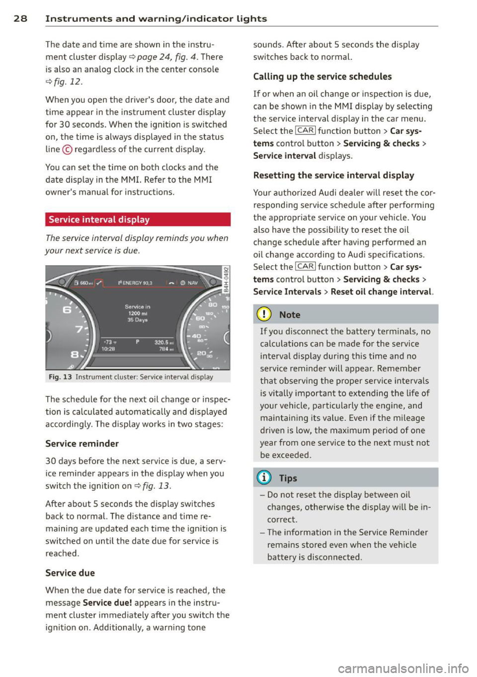
Service interval display
The service interval display reminds you when
your next service is due.
Fig. 13 Inst rume nt cluster: Serv ice inte rval d isp lay
The schedule for the next oil change or inspec
tion is calculated automatically and displayed
accordingly. The display works in two stages :
Service reminder
30 days before the next service is due, a serv
ice reminder appears in the display when you
switch the ignition on
c:;, fig. 13 .
After about S seconds the display switches back to normal. The distance and time re
maining are updated each time the ignition is
switched on until the date due for service is
reached .
Service due
When the due date for service is reached, the
message
Service due! appears in the instru
ment cluster immediately after you switch the
ignition on . Additionally, a warn ing tone sounds. After about 5 seconds the disp
lay
switches back to normal.
Calling up the service schedules
If or when an oil change or inspection is due,
can be shown in the MMI display by selecting
the service interval display in the car menu.
Select the
ICARI function button > Car sys
tems
control button > Servicing & checks >
Service interval displays.
Resetting the service interval display
Your authorized Audi dealer will reset the cor
responding service schedule after performing
the appropr iate service on your vehicle. You
also have the possibility to reset the oil
change schedule after hav ing performed an
o il change according to Aud i specif ications.
Select the
I CAR I function button > Car sys
tems
control button > Servicing & checks >
Service Intervals > Reset oil change interval.
(D Note
If you disconnect the battery term inals, no
calculations can be made for the service
i nterval disp lay during th is time and no
serv ice reminder will appear. Remember
that observing the proper service intervals
i s vitally important to extending the life of
your vehicle, pa rticularly the engine, and
maintaining its value. Even if the mileage
driven is low, the maximum period of one
year from one service to the next must not
be exceeded.
(I} Tips
-Do not reset the display between oil
changes, otherwise the disp lay w ill be in
correct.
- The information in the Service Reminder
remains stored
even when the vehicle
battery is disconnected .
Page 31 of 314
Instrument s and warning /indicator lights
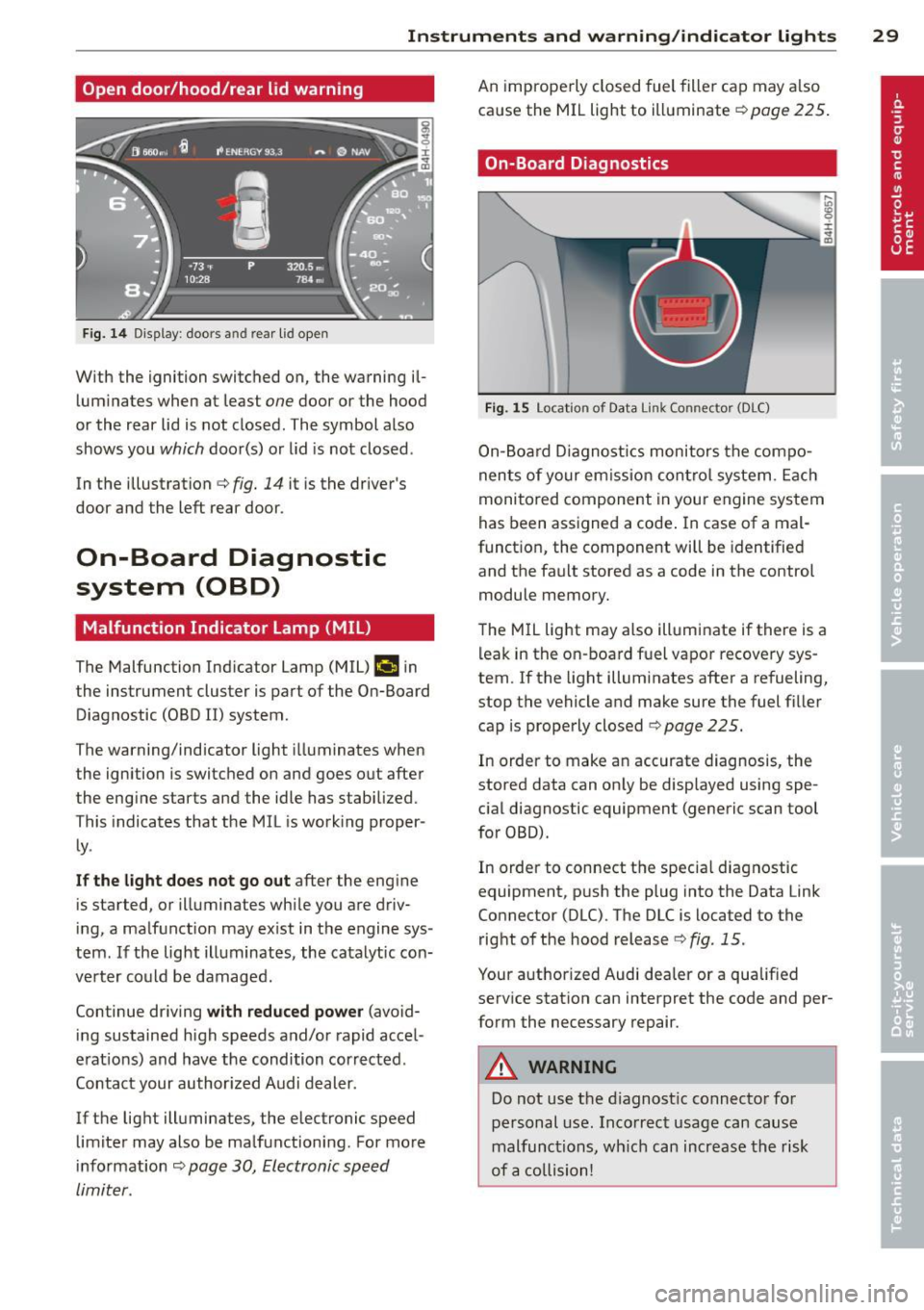
Open door/hood/rear lid warning
Fig. 14 D isplay: doors and rear lid open
With the ignition switched on, the warning il
luminates when at least
one door or the hood
or the rear lid is not closed. The symbol also
shows you
which door(s) or lid is not closed.
In the illustration ¢
fig. 14 it is the driver's
door and the left rear door.
On-Board Diagnostic
system (OBD)
Malfunction Indicator Lamp (MIL)
The Malfunction Indicator Lamp (MIL) ¢4 in
the instrument cluster is part of the On-Board Diagnostic (OBD II) system.
The warning/indicator light illuminates when
the ignition is switched on and goes out after
the engine starts and the idle has stabilized.
This indicates that the MIL is work ing proper
ly .
If the light does not go out after the engine
is started, or illuminates while you are driv
ing, a malfunction may ex ist in the engine sys
tem. If the light illuminates, the catalytic con
verter could be damaged.
Continue driving
with reduced power (avoid
ing sustained high speeds and/or rapid accel
erat ions) and have the condition corrected.
Contact your author ized Audi dealer.
If the light illuminates, the electronic speed limiter may also be malfunctioning. For more
in formation ¢
page 30, Electronic speed
limiter.
An improperly closed fuel filler cap may a lso
cause the MIL light to illuminate¢
page 225.
On-Board Diagnostics
Fig. 15 Location of Data Link Connector (DLC)
On-Board Diagnostics monitors the compo
nents of your emission control system. Each
monitored component in your engine system
has been assigned a code . In case of a mal
funct ion, the component will be identified
and the fault stored as a code in the control
module memory.
The MIL light may also illuminate if there is a leak in the on -board fuel vapor recovery sys
tem.
If the light illuminates after a refueling,
stop the vehicle and make sure the fuel filler
cap is properly closed ¢
page 225.
In order to make an accurate diagnosis, the
stored data can only be displayed using spe
cial diagnostic equipment (generic scan tool
for OBD).
In order to connect the special diagnostic
equipment, push the plug into the Data Link
Connector (DLC). The DLC is located to the
right of the hood release
¢fig. 15.
Your authorized Audi dealer or a qualified
service station can interpret the code and per
form the necessary repair.
A WARNING
Do not use the diagnost ic connector for
personal use. Incorrect usage can cause
malfunctions, wh ich can increase the risk
of a collision!
-
29
Page 49 of 314
Highway light function* (vehicles with LED
headlights) - this function adapts the lighting
for highway driving based on vehicle speed.
.&_ WARNING
-Automatic headlights are only intended
to assist the driver. They do not relieve
the driver of his responsibility to check
the headlights and to turn them on man ually according to the current light and
visibility conditions. For example, fog
cannot be detected by the light sensors.
So always switch on the headlights
~D
under these weather conditions and
when driving in the dark.
- Crashes can happen when you cannot see the road ahead and when you cannot be
seen by other motorists. Always turn on
the headlights so that you can see ahead and so that others can see your car from
the back.
- Please observe legal regulations when
using the lighting systems described.
(D Note
The rear fog lights should only be turned
on in accordance with traffic regulation, as
the lights are bright for following traffic.
(D Tips
- The light sensor* for automatic dynamic
headlight range control* is located in the
rear view mirror mount. You should
therefore not apply any stickers to the
windshield in this area in order to pre
vent malfunctions or failures.
- In the event of a light sensor malfunc
tion, the driver is notified in the instru
ment cluster display~
page 22.
- You will hear a warning tone if you open
the driver door when the exterior lights
are switched on.
- In cool or damp weather, the inside of
the headlights, turn signals and tail
lights can fog over due to the tempera
ture difference between the inside and
outside. They will clear shortly after Clear vision 4
7
switching them on. This does not affect
the service life of the lighting.
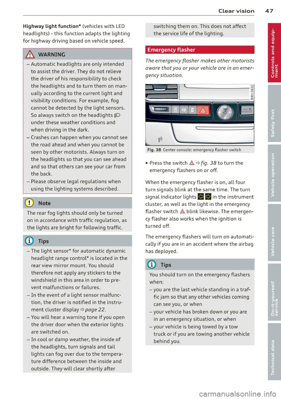
Emergency flasher
Th e emergency flasher makes other motorists
oware that you or your vehicle are in on emer
gency situation.
'1'.r-- ~·
~ ·--~. -~ -..... -._.. l'
1
Fig. 38 Center console: emergency flasher switc h
.,. Press the switch ~ 9 fig. 38 to turn the
emergency flashers on or off .
When the emergency flasher is on, all four
turn signals blink at the same time. The turn
signal indicator lights
H Iii in the instrument
cluster, as well as the light in the emergency
flasher switch~ blink likewise. The emergen
cy flasher also works when the ignition is
turned
off.
The emergency flashers will turn on automati
cally if you are in an accident where the airbag
has deployed.
@ Tips
You should turn on the emergency flashers
when:
-you are the last vehicle standing in a traf
fic jam so that any other vehicles coming
can see you, or when
- your vehicle has broken down or you are
in an emergency situation, or when
-your vehicle is being towed by a tow truck or if you are towing another vehicle behind you.
Page 51 of 314
instrument cluste r ill uminates when the
high beams are on.
- T he
headlight flasher works only as long as
you hold the lever -even if there are no
li ghts turned o n. The indicator light
El in
the instr ument cluster illuminates when you
use the head light flasher.
A WARNING
Do not use the hig h beam or headlight
flasher if you know that these could blind
oncoming traffic.
High beam assist
Applies to vehicles: with high beam ass ist
The high beam assist automatically switches
the high beams on or off, depending on the
surroundings and traffic conditions .
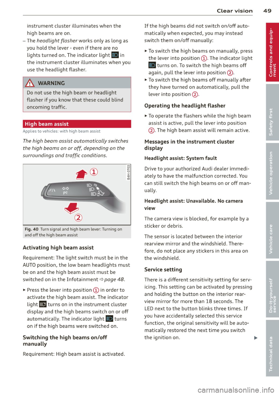
Fig. 40 Turn sig na l and high beam lever: Turning on
and off the high beam ass ist
Activating h igh beam a ssi st
8 .... 0 :i: ;g
Requirement: The light sw itch must be in the
AUTO position, the low beam head lights must
be on and the high beam assist must be
switched on in the Infotainment¢
page 48.
~ Press the lever into position @ in order to
activate the high beam assist. T he indicator
light
Ill turns on in the instrument cluster
display and the high beams switch o n or off
automatically . The indicato r light
II turns
on if the high beams w ere switched on .
Switching the high beams on /off
manually
Requirement: Hig h beam ass ist is activated.
Clear vis ion 49
If the high beams d id not swi tch on/off auto
matically when expected, you may instead
switch them on/off manua lly:
~ To swi tch the high beams on manually, press
the lever into position@. The indicator light
II turns on. To switch the hig h beams off
aga in, p ull the leve r into position @.
~ To switch the high beams off manually after
they have turned on a utomat ica lly, pull the
lever i nto pos ition @.
Oper ating the headlight fla sher
~ To operate the flashe rs while the high beam
assist is act ive, pu ll the lever into position
@ . T he high beam assist will remain act ive.
Messag es in the instrument cluster
di spl ay
Headlight assist: System fault
Drive to your authorized A udi dealer immed i
ate ly to have the ma lfunction corrected. Yo u
can still switch the high beams on or off man
u ally.
Headlight a ssi st: Unavailable . No camera
view
T he came ra v iew is b locked, for example by a
sticker o r debr is.
The sensor is loca ted be tween the inter io r
r earvi ew mirror and the w indshield . There
fo re, do no t place any st ic kers in this a rea on
th e windsh ie ld .
Service setting
There is a d ifferent sens it ivity sett ing for serv
ic ing . Th is sett ing can be activated by pr essing
and hold ing the b utton on the int erio r r ear
view m irror for mo re tha n 1 8 seconds. The
L E D next to the button blinks th ree times.
If
yo u have accidentally se lec ted this service
funct io n, the origi nal sensitivity will be a uto
matically restored the next t ime yo u sw itch
the ignit ion on.
Page 260 of 314
258 Tires and wheels
ve hi cle. C onsult thi s m anual
t o deter mine how this re
d uce s the availabl e cargo
a nd lug gage lo ad ca pacity of
yo ur vehicle .
.,.Che ck the tire sidewall
(¢ page 259 , fig . 212 ) to de
termine the de signa ted lo ad
rating for a specific tire .
Tire service life
The service life of tires depends on a lot of
different things including proper installation
a nd balan cing, correct tire pressure and driv
ing style.
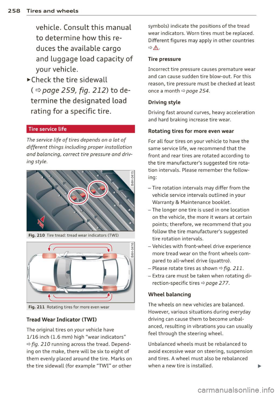
Fig . 210 Tire tread: tread wea r ind icato rs (TWI)
( r------
{ \.._ ______ _.
F ig. 211 Rotat ing t ires for more even wear
Tread Wear Indicator (TWI)
The o rigina l tires on your veh icle have
1/16 inch (1.6 mm) high "wear indicators"
c:::> fig . 210 running across the tread. Depend
ing on the make, there will be six to eight of
them evenly p laced around the t ire . Marks on
the tire s idewall (for example
"TWI" or other symbols) ind
icate the positions o f the tread
wear indicato rs . Worn tires must be replaced .
Different figures may app ly in other countr ies
¢ Ll:). .
Tire pressur e
Incorrect t ire pressure ca uses prema ture wear
and can cause sudden tire blow -out . For this
reason, tire pressure must be checked at least
once a month
c:::> page 254.
Driving style
Dr iving fast around c urve s, he avy a ccele rat ion
and hard braking inc rease tire wear.
Rotating tires for more even wear
Fo r all four tires on your veh icle to have th e
same service life, we recomme nd that the
fron t and rear tires a re rotated ac co rd ing to
the tire m an ufa ctu rer's suggested tire ro ta
tion intervals . Please remembe r th e fo llow
ing :
- Tire rotation in tervals may diffe r from the
ve hicle service inte rva ls o utlin ed in your
Warranty
& M aintena nce booklet.
- The longe r one tire is used in one lo cation
on t he veh icle, the more it wears at cer tain
points; there fore, we recommend that you
follow the tire manufact urer's suggested
tire rotation intervals.
- Vehicles w ith front-whee l dr ive experience
more tread wear on the front w heels com
pa red to a ll-wheel drive (q uattro).
- Please rotate tires as shown
c:::>fig . 211.
- Extra care mus t be taken when ro ta ting di-
rection-specific tires¢
page 2 77.
Wheel balancing
The wheels on new ve hicles are balanced.
However, va rious s ituatio ns dur ing everyday
driv ing c an cause them to become unbal
anced, res ulting in vib rations you can usually
feel thro ugh the steering whee l.
Un balanced w hee ls mu st be rebalanced to
avo id excessive wear on steering, s uspension
and t ires . A whee l m ust also be reba lance d
when a new tire is insta lled .
ll-
Page 308 of 314
306 Index
Securing child safety seats ..... .... . 18 7
Specia l considerations for pregnant
women . ... ................ ..... .
150
Unfastening ............. .. .. .... . 150
Warning/indicator light ...... .. .... . 145
Warning light ............. ... .. ... . 16
WhyYOU MUSTwearthem . .. .. .. .. . 145
Worn properly 147
Safety belt tensioner
drive select . . . . . . . . . . . . . . . . . . . . . . .
11 O
Safety belt warning light ............ .
145
Safety compliance st icker ....... .. .. . 289
Safety equipment ............ .. .... . 135
Safety features for occupant restraint and
protection ... ................ ..... .
135
Safety guidelines
Seat adjustment . . . . . . . . . . . . . . . . . . . .
58
Safety instructions
Engine compartment ...... .. .. .... .
231
for side curtain airbags .. ... ..... .. . 175
for using ch ild safety seats ....... .. . 180
for using safety be lts ....... ... .. ... 148
Monitoring the Advanced Airbag Sys-
tem ... .. .. ... .......... .. .. .. .. .
166
Safety systems
Warn ing/ indicator l ights ....... .. ....
18
Seat adjustment
Controls (front seats) . . . . . . . . . . . . . . . .
59
Controls (rear seats) ...... .. .. .... .. 61
Driver 's seat . . . . . . . . . . . . . . . . . . . . . . . 58
Front passenger's seat . . . . . . . . . . . . . . . 59
Front seats . . . . . . . . . . . . . . . . . . . . . . . . 58
H ead restraints 65 ,139
Reclining rear seat ...... .. .. .. .. .. .. 62
Safety guide lines ......... .. .. .. .. .. 58
Seat belts
WhyYOU MUSTwearthem
Seat covers Cleaning
145
219
Seat heating/ventilation .......... .. .. 81
Seating position
Driver
Front passenger ... ..... .. .. .. .. .. .
Ho w to adjust the front seats . .. .. .. .
136
137
137
Incorrect seat position ............. . 139
Occupants . ................. ..... . 136
Rear passengers ................... 138
Seat memory . . . . . . . . . . . . . . . . . . . . . . . 66
Seats
Comfort seat side view ......... .... .
67
Seat symmetry ... ............. .. .. . 67
Seats (number) .. .. .. .. ...... ... .. .. 145
Se lective catalytic reduction
refer to Ad Blue ... ................ . 227
Selective unlock feature . . . . . . . . . . . . . . . 34
Selector lever . . . . . . . . . . . . . . . . . . . . . . 116
Service and disposa l
Safety be lt pretensioner ........ .. ..
152
Serv ice interval display . . . . . . . . . . . . . . . . 28
Service position
refer to Windshield wipers .. .... .. .. . 54
Servotronic (power steering system) . ... 203
Sh iftpadd les .. .. .. .......... ...... . 119
Ship (transporting your vehicle) .... .. .. 287
Shutting down vehicle ......... .... .. 209
Side a irbags
D .. escnpt1on .. .. .. .......... ...... .
How they work ... ... ...... .... .. . .
Side assist
. . .. .. .. ............. ....
Activating and deactivating ...... .. . .
Adjusting the brightness ........... .
Cleaning the sensors ............ .. .
Sensor range .. .. .. .. ...... ... .. . .
Side curtain airbags ............. ... .
D . t' escnp ,on .... .. ............. ... .
How they work . .. ................ .
Safety instructions ....... ...... .. . .
171
172
106
108
108
217
107
174
174
175
175
Side marker lights . ............. .. .. . 46
Ski sack
refer to Pass-through with ski sack .. .. . 71
Sliding/tilting sunroof
E l · mergency c osing . . . . . . . . . . . . . . . . . . 44
Emergency operation . . . . . . . . . . . . . . . . 45
Opening and closing ............. .. . 43
Panoramic sunroof ............. .... . 44
Snow chains ...... ................ . 264
Sockets . . . . . . . . . . . . . . . . . . . . . . . . 68, 74
Solar operation (automatic climate con-
tro l) ... .... .... .. ............. .... .
82
Sources of information about child re-
straints and their use ............. ...
196
Space-saving spare tire ............ ... 271