emergency towing AUDI A8 2018 Owners Manual
[x] Cancel search | Manufacturer: AUDI, Model Year: 2018, Model line: A8, Model: AUDI A8 2018Pages: 356, PDF Size: 54.71 MB
Page 6 of 356
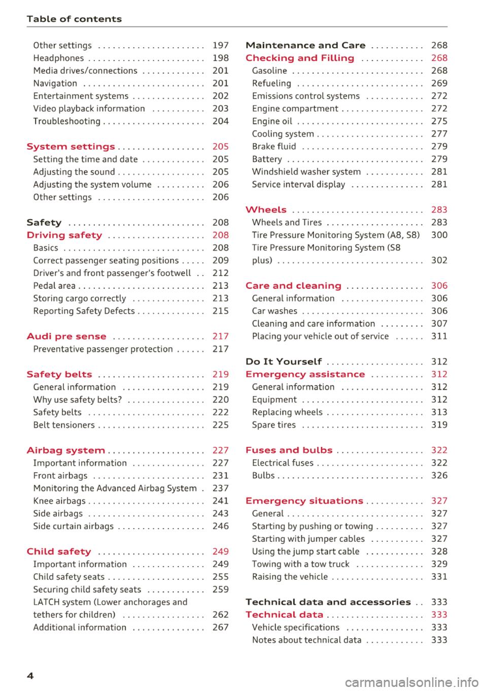
Table of contents
Other settings . . . . . . . . . . . . . . . . . . . . . . 197
H eadphon es . . . . . . . . . . . . . . . . . . . . . . . . 198
M edia drives/connect ions . . . . . . . . . . . . . 201
Navigation . . . . . . . . . . . . . . . . . . . . . . . . . 201
Enterta inment systems . . . . . . . . . . . . . . . 202
Video playback information . . . . . . . . . . . 203
T roubleshoot ing . . . . . . . . . . . . . . . . . . . . . 204
System settings . . . . . . . . . . . . . . . . . . 205
Sett ing the time and date . . . . . . . . . . . . . 205
Ad justi ng the sound . . . . . . . . . . . . . . . . . . 205
Ad justi ng the system vo lume ... .... .. .
Othe r settings .. ............. .. .. .. . 206
206
Safety .. .. .. .. ... .. ..... ... .. .. .. . 208
Driving safety . . . . . . . . . . . . . . . . . . . . 208
B asics . . . . . . . . . . . . . . . . . . . . . . . . . . . . . 20 8
Cor rect passenger seating positions . . . . . 209
D river's and front passenge r's footwell . . 212
Peda l area. ........ .. ..... ... .. .. ... 213
Storing cargo correctly . . . . . . . . . . . . . . . 213
Report ing Safety Defects....... .... .. . 215
Audi pre sense . . . . . . . . . . . . . . . . . . . 217
Preventative passenger protection . . . . . . 217
Safety belts . . . . . . . . . . . . . . . . . . . . . . 2 19
Gene ral information . . . . . . . . . . . . . . . . . 219
W hy use safety belts? . . . . . . . . . . . . . . . . 220
Safety belts . . . . . . . . . . . . . . . . . . . . . . . . 222
Belt tensioners . . . . . . . . . . . . . . . . . . . . . . 225
Airbag system . . . . . . . . . . . . . . . . . . . . 227
Important information . . . . . . . . . . . . . . . 227
F ront a irbags . . . . . . . . . . . . . . . . . . . . . . . 23 1
M on itor ing t he Advanced Airbag System . 237
Knee ai rbags . . . . . . . . . . . . . . . . . . . . . . . . 24 1
Side air bags . . . . . . . . . . . . . . . . . . . . . . . . 24 3
Side c urtain airbags . . . . . . . . . . . . . . . . . . 246
Child safety . . . . . . . . . . . . . . . . . . . . . . 24 9
I mportant info rmation . . . . . . . . . . . . . . . 24 9
Chi ld safety seats . . . . . . . . . . . . . . . . . . . . 255
Securing chi ld safety seats . . . . . . . . . . . . 259
LATCH system (Lower anchorages and
tethers for children) . . . . . . . . . . . . . . . . . 262
Add it io nal information . . . . . . . . . . . . . . . 267
4
Maintenance and Care . . . . . . . . . . . 2 68
Checking and Filling . . . . . . . . . . . . . 268
Gasoline . . . . . . . . . . . . . . . . . . . . . . . . . . . 268
Refueling . . . . . . . . . . . . . . . . . . . . . . . . . . 269
Emissions control systems . . . . . . . . . . . . 272
Engine compartment . . . . . . . . . . . . . . . . . 272
E ngine o il . . . . . . . . . . . . . . . . . . . . . . . . . . 275
Cooli ng system . . . . . . . . . . . . . . . . . . . . . . 277
B rake fl uid . . . . . . . . . . . . . . . . . . . . . . . . . 279
Bat tery . . . . . . . . . . . . . . . . . . . . . . . . . . . . 279
Windsh ie ld washer sys tem . . . . . . . . . . . . 281
Service in terva l display 281
Wheels .... .. .. .. .. ............. .. 28 3
Whee ls and Tires . . . . . . . . . . . . . . . . . . . . 283
T ire Pressure Monitoring System (AB , 58) 300
Tire P ressure Monitor ing System (58
pl us) . . . . . . . . . . . . . . . . . . . . . . . . . . . . . . 302
Care and cleaning . . . . . . . . . . . . . . . . 306
Genera l information . . . . . . . . . . . . . . . . . 306
Car washes . . . . . . . . . . . . . . . . . . . . . . . . . 306
Cleaning and care info rmation . . . . . . . . . 307
Plac ing your vehicle out of serv ice . . . . . . 311
Do It Yourself . . . . . . . . . . . . . . . . . . . . 312
Emergency assistance . . . . . . . . . . . 312
Genera l information . . . . . . . . . . . . . . . . . 312
E qu ipment . . . . . . . . . . . . . . . . . . . . . . . . . 312
Repla cing wheels . . . . . . . . . . . . . . . . . . . . 313
Spa re tir es . . . . . . . . . . . . . . . . . . . . . . . . . 319
Fuses and bulbs . . . . . . . . . . . . . . . . . . 32 2
El ec trica l fuses . . . . . . . . . . . . . . . . . . . . . . 322
B ul bs . . . . . . . . . . . . . . . . . . . . . . . . . . . . . . 3 26
Emergency situations . . . . . . . . . . . . 327
Gener al . . . . . . . . . . . . . . . . . . . . . . . . . . . . 32 7
Start ing by p ushi ng o r tow ing . . . . . . . . . . 3 27
Starting with jumper cab les . . . . . . . . . . . 327
U sing the jump start cable . . . . . . . . . . . . 328
Towing with a tow truck . . . . . . . . . . . . . . 329
Raising the vehicle . . . . . . . . . . . . . . . . . . . 331
Technical data and a ccessories . . 333
Technical data . . . . . . . . . . . . . . . . . . . . 333
Vehicle specificat ions . . . . . . . . . . . . . . . . 333
Notes abo ut technical data . . . . . . . . . . . . 333
Page 27 of 356
u. co .... N
" N .... 0 0 :c '
Audi Service Facility immediately to have t he
mal funct ion corrected.
~ D Light/rain sensor
El Automatic headl ights / automatic wipe rs:
System fault
The light/rain sensor is malfunctioning.
The low beams remain swi tched on at all times
for safety reasons when the light switch is in the
AU TO position. You can continue to turn the
lights on and
off using the light switch . You can
still control all functions that are independent of
the ra in sensor through the w indshie ld w iper lev
er .
Drive to an aut horized Audi dea ler or a uth orized
Aud i Service Facility immediately to have the
malfunct ion corrected.
!-: Sport differential
Applies to: vehicles with sport differential
(I Sport differential : Sy stem fault
T here is a malfunction with the sport differentia l.
Dri ve to an authorized Aud i dea le r o r a uth orized
Audi Service Facility immediately to have t he
malfunction corrected.
I'll Sport differential : Ov erh eating
The transm iss ion temperature has increased s ig
ni ficantly due to the sporty driving manne r. D rive
in a less sporty manner until the temperature re
turns to the normal range and the ind icator ligh t
sw itches of .
A WARNING
Contact an author ized A udi dealer or au tho r
ized Aud i Serv ice Facility if the sport diffe ren
tial is fau lty or mal functioning. The repair
must be performed by tra ined personne l us
ing the correct oi l in order to ens ure safety .
Cockpit o ver view
¢¢Turn signals
If the B or 1B in d icator light blinks , the tur n
s ignals a re act ivated. If bot h ind icator lights are
blinking, the emergency flashers are activa ted.
If an ind icator light blinks tw ice as fast as usual,
a turn signal b ulb has fai led. Carefully d rive to an
a utho riz ed Aud i dea le r or autho rized Aud i Serv ice
F ac ility immed iate ly to have the ma lfunction co r
rected . The indicator light does not indicate a
malfunction if a turn signal on the trailer o r on
the vehicle fa ils in trailer towing mode.
(D Tips
F o r more information on the turn signa ls, re
fer
to~ page 44.
On-Board Diagnostic
System (OBD)
Malfunction Indicator Lamp (MIL)
The Ma lfunction Indicato r Lamp ( MIL) ¢..ijj in the
instrument cluster is part of the On -Board Diag
nostic (OBD II) system .
T he warning/indicator lig ht ill uminates w hen the
ignition is switched on and goes out after the en
gine starts and the id le has stabilized . This indi
cates that the MIL is wor king properly.
If the light doe s not go out after the eng ine is
started, or i lluminates while you are driving, a
malfunction may exist in t he engine system. If
the light ill uminates, the catalytic converter
could be damaged.
Continue driving
w ith reduced powe r (avoiding
s u stained high speeds and/or rapid accelera
tions) and have the condit ion corrected. Contact
your authori zed Aud i dea ler .
If the light i lluminates, the electronic speed lim
iter may also be malf unctioning. For more infor
mation
c> page 26, Electronic speed limiter .
An improperly closed fue l filler cap may also
ca use the M IL light to ill uminate
c> page 2 70.
25
Page 83 of 356
lL t:0 ....
"' ......
"' .... 0 0 :c '
parking brake
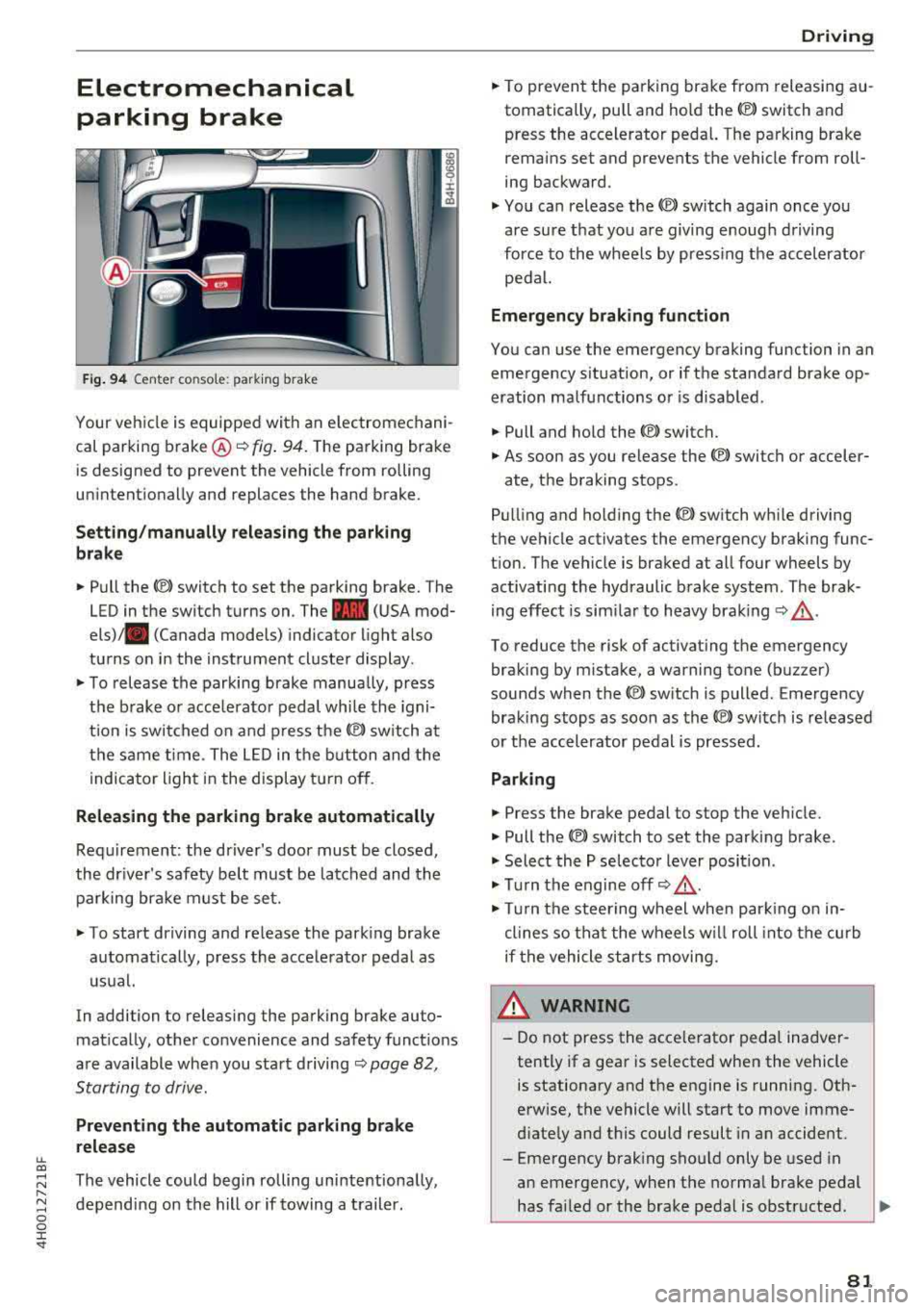
Fig. 94 Center console: parking brake
Your vehicle is equipped with an electromechani
cal parking brake ®
i=)fig. 94. The parking brake
is designed to prevent the vehicle from rolling
unintentionally and replaces the hand brake.
Setting/manually releasing the parking
brake
.. Pull the C®> switch to set the parking brake. The
LED in the switch turns on. The
-(USA mod
els) . (Canada models) indicator light also
turns on in the instrument cluster display.
.. To release the parking brake manua lly, press
the brake or acce lerator pedal while the igni
t ion is switched on and press
the(®) switch at
the same time. The LED in the button and the
indicator light in the display turn off.
Releasing the parking brake automatically
Requirement: the driver's door must be closed,
the driver's safety belt must be latched and the parking brake must be set.
.. To start driving and release the parking brake
automatically, press the accelerator pedal as
usual.
In addition to releasing the parking brake auto
matically, other convenience and safety functions
are available when you start driving
i=)page 82,
Starting to drive.
Preventing the automatic parking brake
release
The vehicle could begin rolling unintentionally,
depending on the hill or if towing a trailer.
Driving
.. To prevent the parking brake from releasing au
tomatically, pull and hold the<®> switch and press the accelerator pedal. The parking brake
remains set and prevents the vehicle from roll
ing backward .
.,. You can release the<®> switch again once you
are sure that you are giving enough driving
force to the wheels by pressing the accelerator
pedal.
Emergency braking function
You can use the emergency braking function in an
emergency situation, or if the standard brake op
eration malfunctions or is disabled.
.. Pull and hold the<®> switch.
.. As soon as you release the <®> switch or acceler-
ate, the braking stops.
Pulling and ho lding
the(®) switch while driving
the vehicle activates the emergency braking func
tion. The vehicle is braked at all four wheels by activating the hydraulic brake system. The brak
ing effect is similar to heavy braking
i=) ,& .
To reduce the risk of activating the emergency
braking by mistake, a warning tone (buzzer)
sounds when the
<®l switch is pulled. Emergency
braking stops as soon as
the© switch is released
or the accelerator pedal is pressed.
Parking
.. Press the brake pedal to stop the vehicle.
.. Pull the<®> switch to set the parking brake .
.,. Select the P selector lever position .
.,. Turn the engine off i=) ,&.
.,. Turn the steering wheel when parking on in
clines so that the wheels w ill roll into the curb
if the vehicle starts moving.
8_ WARNING
-Do not press the acce lerator pedal inadver
tently if a gear is selected when the vehicle
is stationary and the engine is running. Oth
erwise, the vehicle will start to move imme
diately and this could result in an accident.
-Eme rgency braking should only be used in
an emergency, when the normal brake pedal
has failed or the brake pedal is obstructed .
.,.
81
Page 86 of 356
Drivin g
you can s hift past the N and R se lector lever
positions.
Selector lever lock
The se lector lever lock prevents you from se lect
ing a posit ion un intent ionally, causing the vehicle
to ro ll. When engaging some selector lever posi
tions, you must press the button on the selector
lever ¢ fig. 96 and/or press the brake pedal.
You must p ress t he brake pedal to engage a se
lector lever posit ion when the engine is running
and the vehicle is stationary . The arrows ¢
fig. 97
indicate when you need to press the button on
the selector lever.
The se lector lever does not lock if you shift from
D to R within one second . This a llows you to
"rock" the vehicle to free it when it is stuck.
P - Park
This se lecto r lever position p revents the veh icle
from roll ing. Only s hift into park w hen the veh i
cle is
stationary ¢.&. . To engage the P selector
lever position, press the button on the selector
lever and s hift into t he P position .
You can on ly shift out of pa rk when the engine is
running and you are pressing the brake peda l. To
release the parking lock . press the b utton on the
selector lever and select the desired position .
P engages automat ically when you switch the en
gine
off while D, Sor R is engaged or in manual
mode .
I f you sw itch the engine off w hen the N pos ition
is selected, the t ransm iss ion rema ins in N fo r ap
p roximate ly 30 minutes and then Pis engaged .
You must use the park ing lock emergency release
befo re towing the
vehicle¢ page 88.
R- Reverse
The reverse gear is engaged in this pos ition. Only
select reverse gear when the veh icle is stationary
and the eng ine is running at idle
speed ¢.&, . To
e n gage the R selecto r leve r pos it ion, press the
button on the selector lever, p ress the brake ped
a l and move the se lector lever into the R pos it io n .
84
The reverse lights turn on when you select the R
selector lever position whi le the engine is run
ning.
N -Neutral (idle )
The transmission is in idle in th is position. To en
gage the N selector leve r position, press the but
ton on the selector lever and shift into the N po
sition .
If you switc h the eng ine
off when the N pos it io n
i s selected, the transmission remains in N for ap
proximately 30 minutes and then Pis engaged.
Yo u cannot se lect t he N pos it ion when the ig ni
t ion is switched
off. When dr iv ing t hrough an au
tomat ic car wash, fi rst select the N position and
t h en turn the engine off ¢
page 306.
For safety reasons, the veh icle cannot be loc ked
whe n the t ransmiss io n is in t he N pos it io n.
D IS -Driving forward
When the transm ission is in the D/S posit ion, it
can be operated e ither in the normal D mode or
i n the S sport mode. Move the selector lever back
to engage the S sport mode. You ca n only select
t h e S se lector lever position when D is engaged.
To se lect the D selector lever position again w hen
S is engaged, move the selector lever
back¢ &..
To s hift from N to D w hen traveling at speeds be
l ow 1 mp h (2 km/h), press the br ake pedal and
shi ft into the D
position ¢.&. .
In the normal mod e D, the transmission auto
matically selec ts the su itable gear ratio .
It de
pends on engine load , veh icle speed a nd d rivi ng
sty le.
Se lect the
s port mod e S for spo rty d riving. The
vehicle makes f ull use of the eng ine's power.
S hi ft ing may become no ticeable when acceler at
i ng .
The S se lecto r lever posit io n engages automat i
ca lly w hen you sele ct dynamic mode in d rive se
l ect .
& WARNING
-The vehi cle can roll even if the ignit ion is
switched
off .
-
Page 90 of 356
Driving
-The park ing lock can no longer be engaged.
Drive to an authorized Audi dealer or author
ized Audi Service Facility immed iately to have
the malfunction corrected.
rm Transmission malfunction: Stop vehicle and
shift to park.
Do not continue driving. Select the P selec tor lev
er position and contact an authorized Audi dea ler
or authorized Audi Service Facility for assistance.
Parking lock emergency release
The parking lock must be released using the
emergency release before towing the vehicle.
®
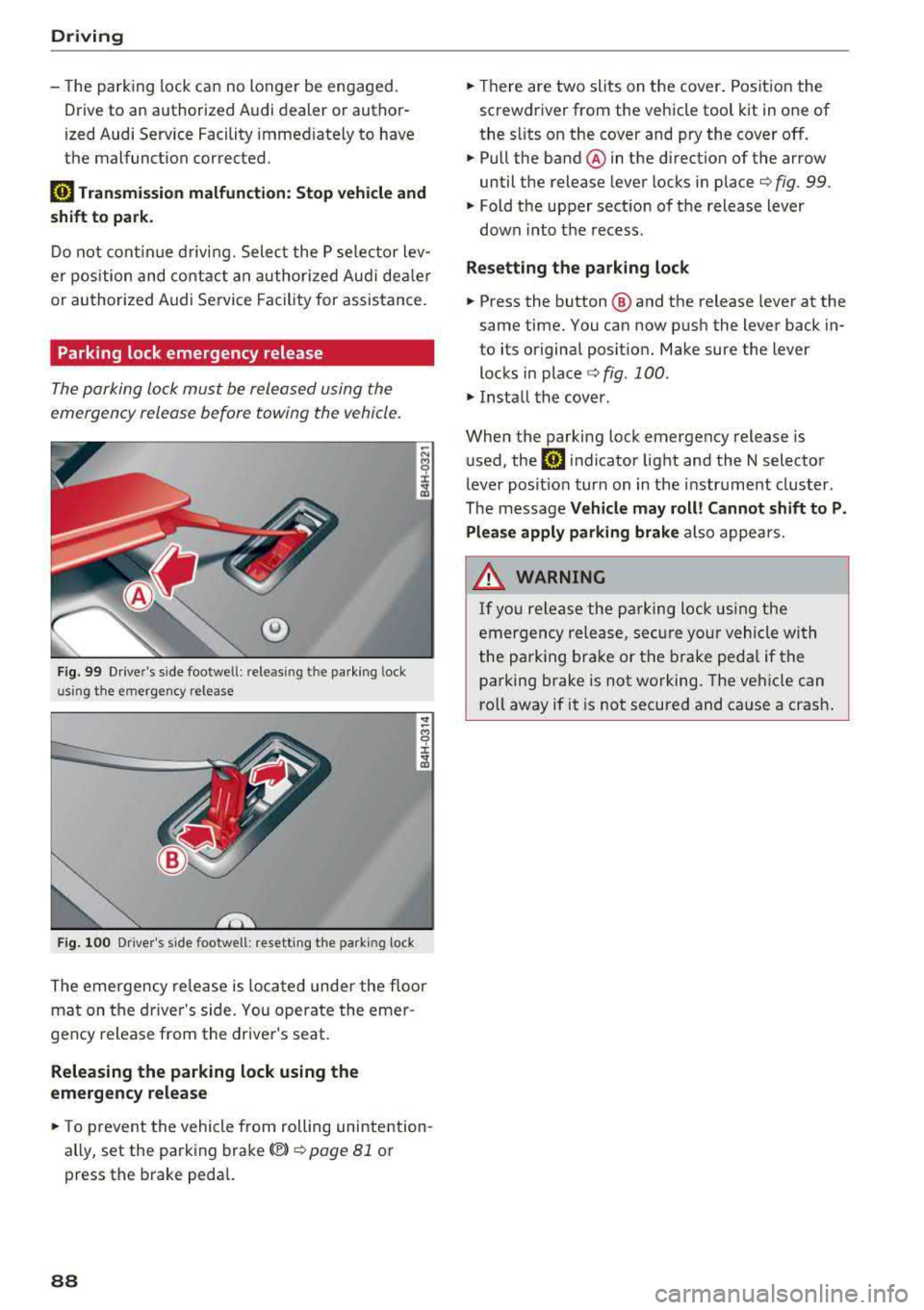
Fig. 99 Drive r's side footwe ll: releasin g t he parking lock
u sin g th e emergency release
Fig . 100 Dr iver's s ide footwell: resett ing the park ing lock
The emergency re lease is located under the floor
mat on the driver 's side. You operate the emer
gency release from the driver's seat.
Releasing the parking lock using the
emergency release
.,. To prevent the vehicle from rolling unintention
ally, set the parking brake(®)
¢ page 81 or
press the brake pedal.
88
.,. Th ere are two slits on the cover. Position the
screwdriver from the vehicle tool kit in one of
the s lits on the cover and pry the cover off.
.,. Pull the band ® in the direction of the arrow
until the release lever locks in place
¢ fig. 99 .
.,. Fold the upper sect ion of the release lever
down into th e recess.
Resetting the parking lock
.,. Press the button @ and the release lever at the
same time. You can now push the lever back in
to its original posit ion. Make sure the lever
locks in
place ¢ fig. 100 .
.,. Install the cover .
When the parking lock emergency release is
used, the
rm indicator light and the N selector
lever posit ion turn on in the instrument cluster.
The message
Vehicle may roll! Cannot shift to P.
Please apply parking brake
also appears .
.&, WARNING
-
If you release the parking lock using the
emergency release, secure your vehicle with
the pa rking brake or the brake pedal if the
parking brake is not working. The vehicle can
ro ll away if it is not secured and cause a crash.
Page 315 of 356
u. co .... N
" N .... 0 0 :c '
c ident.
- The factory-supplied jack is intended on ly
for your vehicle m odel. Under no circum
stances should it be used to lift heavy
vehicles or other loads; you r isk injuring
yourself .
- Never start the en gine when the vehicle is
ra ised, which could cause an accident .
- Support the veh icle secure ly w ith appropr i
ate stands if work is to be performed under
neath the vehicle; otherwise, there is a po
tent ial risk for in ju ry .
- Never use the jack supplied with your Audi
on another vehicle, particularly on a heav ier
one . The jack is only suitable for use on the
vehicle it came w it h .
(D Tips
The vehicle jack* in your vehicle is mainte
na nee -free .
Replacing wheels
Before changing a wheel
Observe the following precautions for your own
and your passenger's safety when changing a
wheel.
.,. After yo u experience a tire fail ure, pull the car
we ll away from moving t raffic and t ry to rea ch
level g round before you s top ¢&, .
.,. All passengers sho uld lea ve the ca r and move
to a saf e location (for instance, be hind t he
guardrai l) ¢ &, .
.,. Engage the parking brake to prevent you r vehi
cle from rol ling
unintentionally ¢ A_.
.,. Move selector lever to position P ¢ A_.
.,. If you a re towing a trailer, unh itch the trailer
from your ve hicle.
.,. Take the jack and the spare tire ou t of the lug
gage compa rtment
¢ page 312.
A WARNING
You or your passengers cou ld be inju red wh ile
chang ing a wheel if you do not follow these
safety precautions :
Emergenc y ass is tanc e
-If you have a flat tire, move a safe distance
off the road. Turn off the eng ine, turn the
emergency flashers on and use other warn ing dev ices to alert other motorists .
- Make sure that passengers wait in a safe
p lace away from the vehicle and well away
from the road and traff ic .
- To help prevent the veh icle from moving
suddenly and possib ly slipping off the jack ,
always fu lly set the par king brake and block
the front and back of the wheel diagonally
opposite the wheel being changed. W hen
one front w heel is li fted off the gro und,
p lacing the Au tom atic Transmi ssion in P
(Park) will
not p revent the vehicle from
mov ing.
- Before you change a wheel, be sure the
g ro u nd is leve l and firm. If necessary, use a
sturdy board under the jack .
- Always s tore the vehicle tool ki t, the jack
an d the replaced tire in the luggage com
pa rtment ¢
page 213 .
(D Tips
Befo re c hangin g the wheel, you mus t activ ate
the jacking mode, so that the a utomat ic con
tro ls for the Adaptive Air Suspension do not
make it more di fficult to lift the vehicle with
the jack
¢ page 315 .
Changing a wheel
When you change a wheel , follow the sequence
described below step -by-step and in exactly that
order .
1. Activate the vehicle jack mode ¢ page 315 .
2. Remove the de corative wheel cover *. For
more detai ls see
a lso ¢ page 314, Decora
tive wheel covers
or ¢ page 314, Wheels
with wheel bolt caps .
3. Loosen the wheel bolts ¢ page 315 .
4. Loca te t he p roper mount ing point for the
jac k and alig n the jack be low that po int
¢page 315 or ¢ page 316.
S. Rai se the ca r wi th the jack ¢ page 315 or
¢page 316 .
313
Page 329 of 356
u. co .... N
" N .... 0 0 :c '
General
This chapter is intended for trained emergency
crews and working personnel who have the nec
essary tools and equipment to perform these
operations.
Starting by pushing or
towing
~ Note
Vehicles with an automatic transmission can
not be started by pushing or towing.
Starting with jumper
cables
If necessary, the engine can be started by con
necting it to the battery of another vehicle .
If the engine should fail to start because of a dis
charged or weak battery, the battery can be con
nected to the battery of
another vehicle, using a
pair of jumper cables to start the engine.
Jumper cables
Use only jumper cables of sufficiently large cross
section
to carry the starter current safely. Refer
to the manufacturer's specifications.
Use only jumper cables with
insulated terminal
clamps which are distinctly marked :
plus(+) cable in most cases colored red
minus(-) cable
in most cases colored black.
A WARNING -
Batteries contain electricity, acid, and gas.
Any of these can cause very serious or fatal in
jury. Follow the instructions below for safe
handling of your vehicle's battery .
-Always shield your eyes and avoid leaning
over the battery whenever possible.
-A dead battery can freeze at temperatures
around 32 °F (0 °C) . If the vehicle battery is
frozen, you must thaw it before connecting
the jump start cables. If you do not, this in-
Emergency situations
creases the risk of an explosion and chemi
cal burns. After jump starting the vehicle,
drive to an authorized Audi dealer or author ized Audi Service Facility immediately to
have the vehicle battery checked.
- Do not allow battery acid to contact eyes or
skin . Flush any contacted area with water
immediately.
- Improper use of a booster battery to start a
vehicle may cause an explosion .
- Vehicle batteries generate explosive gases .
Keep sparks, flame and lighted cigarettes
away from batteries.
- Do not try to jump start any vehicle with a
low acid level in the battery .
- The voltage of the booster battery must also
have a 12-Volt rating . The capacity (Ah) of
the booster battery should not be lower
than that of the discharged battery. Use of
batteries of different voltage or substantial
ly different "Ah " rating may cause an explo
sion and personal injury.
- Never charge a frozen battery. Gas trapped
in the ice may cause an explosion.
- Never charge or use a battery that has been
frozen. The battery case may have be weak
ened.
- Use of batteries of different voltage or sub
stantially different capacity (Ah) rating may
cause an explosion and injury. The capacity
(Ah) of the booster battery should not be
lower than that of the discharged battery.
- Before you check anything in the engine
compartment, always read and heed all
WARNINGS
c>page 272.
@ Note
- Applying a higher voltage booster battery
will cause expensive damage to sensitive
electronic components, such as control
units, relays, radio, etc.
- There must be no electrical contact between
the vehicles as otherwise current could al
ready start to flow as soon as the positive
( + ) terminals are connected.
327
Page 331 of 356
-When connecting jumper cables, make sure
that they cannot get ca ught in any mov ing
parts in the engine compartment.
- Before you check anything in the engine
compartment, a lways read and heed a ll
WARNINGS
¢ page 272.
(D Note
Impro per hook-u p of jum per cables can ru in
the generato r.
- Always connect P OSITIVE( +) to POSITIV E
( + ), and NEGATIVE( -) to NEGATIVE( -)
g round post of the battery manager contro l
unit.
- Check that a ll sc rew p lugs on the battery
cells are sc rewed in firmly . If not, t ighten
pl ugs p rior to connect ing clamp on negative
b atte ry te rmi nal.
- Please note t hat the procedure fo r con nect
i ng a jumper cab le as desc ribed above ap
p lie s specifica lly to the case of yo ur vehicle
b eing ju mp starte d. When you are g iv ing a
ju mp s tart to ano ther vehicle, do
not con
n ect th e neg ative( -) ca b le to the neg ative
(-) t ermin al on t he disch arged batte ry @
¢ fig . 290. Instead, securely connect the
negat ive(- ) cab le to either a solid metal
component that is f irm ly bolted to the en
gine block o r to the engine bloc k itself. If
the battery that is be ing c ha rged does not
vent to the outs ide, escap ing batte ry gas
could ignite and ex plod e!
Towing with a tow truck
General hints
Yo ur Audi requires special h andling for towing .
The follow ing informa tion is to be used by com
mercia l tow tr uck o pera tors who know how to op
e rat e the ir equip men t sa fely.
- Never tow your Audi. Towing will cause dam
age to the engine and transmission.
- Never wrap the safety chains or winch cables
~ around the brake lines. ....
~ -To prevent unnecessary damage, your Audi N
8 must be transported with a flatbed truck. 0 :c '
-To load the vehicle on to the flatbed, use the
towing loop found in the vehicle tools and at
tach to the front or rear anchorage
¢ page 329 and c> page 330.
A WARNING
A veh icle being towed is not safe for passen
ge rs. Neve r allow a nyo ne to ride in a vehicl e
b eing towed, fo r any reason.
Front towing loop
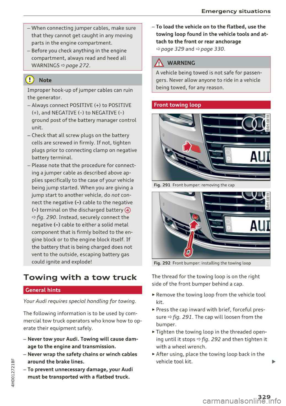
Fi g. 291 Fron t bu mpe r: removing t he cap
Fig. 292 Fron t bu mpe r: insta llin g the tow ing loop
The thread for the towing loop is on the right
s ide of the front bumper beh ind a cap.
.,. Remove the towing loo p from the vehicle too l
kit.
.,. Press the cap inward with brief, forceful pres
sure
c> fig. 291 . The cap will loosen from the
bumper.
.,. T igh ten the tow ing loop in the threaded open
ing until it stops
c> fig. 292 and t hen tighten it
w ith a wheel w re nc h .
.,. Afte r usi ng, p lace the tow ing loop b ack in the
veh icle tool kit.
IJJ>-
329
Page 332 of 356
Emergency situations
& WARNING
If the towing loop is not tightened until it
stops when installing, the threads may be
pulled out when towing the vehicle and that
could cause an accident.
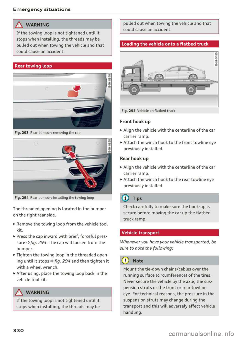
Rear towing loop
Fig. 293 Rear bumper: re moving the cap
Fig. 294 Rear bumper : installi ng the towing loop
The threaded opening is located in the bumper
on the right rear side .
• Remove the towing loop from the vehicle tool
kit .
• Press the cap inward with brief, forceful pres
sure ¢
fig. 293 . The cap will loosen from the
bumper .
• Tighten the towing loop in the threaded open
ing until it
stops¢ fig. 294 and then tighten it
with a whee l wrench .
• After using, place the towing loop back in the
vehicle tool kit.
A WARNING
If the towing loop is not tightened until it
stops when installing, the threads may be
330
-
pulled out when towing the vehicle and that
could cause an accident .
Loading the vehicle onto a flatbed truck
Fig. 295 Vehicle on f latbed tru ck
Front hook up
• Align the vehicle with the centerline of the car
carrier ramp.
• Attach the winch hook to the front towline eye
previously installed.
Rear hook up
• Align the vehicle wi th the centerl ine of the car
carrier ramp.
• Attach the w inch hook to the rear towline eye
previously installed.
@ Tips
Check carefully to make sure the hook-up is
secure before moving the car up the flatbed
truck ramp.
Vehicle transport
Whenever you hove your vehicle transported, be
sure to note the following:
(D Note
Mount the tie-down chains/cables over the
running surface (ci rcumference) o f the tires.
Never secure the vehicle by the axle, the sus
pension struts or the front or rear towline
eye. For technical reasons, the pressure in the
suspension struts may change during the
transport and this will adversely affect vehicle handling.
Page 348 of 356
Index
Rear fog lights . . . . . . . . . . . . . . . . . . . . . . . 43
Side marker lights . . . . . . . . . . . . . . . . . . . . 43
Light/rain sensor Headlights . . . . . . . . . . . . . . . . . . . . . . . . . . 43
I ntermittent mode (w indshie ld wipers) . . . SO
Lighting Exterior . . . . . . . . . . . . . . . . . . . . . . . . . . . . . 43
I nterior . . . . . . . . . . . . . . . . . . . . . . . . . . . . . 46
Lights Interior/reading lights . . . . . . . . . . . . . . . . 46
Interior lighting . . . . . . . . . . . . . . . . . . . . . . 46
Listening to music
refer to Media . . . . . . . . . . . . . . . . . . 181, 190
Listening to the radio MMI control panel . . . . . . . . . . . . . . . . . . . 178
RSE ............................... 202
L ocking/un locking . . . . . . . . . . . . . . . . . . . . . 30
Low-profile tires . . . . . . . . . . . . . . . . . . . . . . 299
L ow beams . . . . . . . . . . . . . . . . . . . . . . . . . . . 43
Luggage compartment . . . . . . . . . . . . . . . . . . 65
12 volt socket . . . . . . . . . . . . . . . . . . . . . . . . 61
Storing cargo correctly . . . . . . . . . . . . . . . 213
Stowing luggage . . . . . . . . . . . . . . . . . . . . 213
Valet parking function . . . . . . . . . . . . . . . . . 40
Luggage compartment lid . . . . . . . . . . . . 33, 36
Opening from the inside in an emergency . 36
Luggage rack . . . . . . . . . . . . . . . . . . . . . . . . . . 65
L umbar support . . . . . . . . . . . . . . . . . . . . . . . 56
M
Maintenance . . . . . . . . . . . . . . . . . . . . . . . . . 336
Maintenance intervals . . . . . . . . . . . . . . . . . 281
Making emergency call.......... .... .. . 151
Malfunction Indicator Lamp (MIL) . . . . . . . . 25
Map Online . . . . . . . . . . . . . . . . . . . . . . . . . . . . . 172
Operating . . . . . . . . . . . . . . . . . . . . . . . . . . 171
Set tings . . . . . . . . . . . . . . . . . . . . . . . . . . . 173
Massage function . . . . . . . . . . . . . . . . . . . 54, 56
Mechanical key . . . . . . . . . . . . . . . . . . . . . 28, 29
Mechanical key (replacement key) . . . . . . . . . 28
Media . . . . . . . . . . . . . . . . . . . . . . . . . . . . . . 190
Audi music interface . . . . . . . . . . . . . . . . . 186
Bluetooth audio player . . . . . . . . . . . . . . . 184
Drives (MMI) . . . . . . . . . . . . . . . . . . . . . . . 181
Format . . . . . . . . . . . . . . . . . . . . . . . . . . . . 187
346
Jukebox . . . . . . . . . . . . . . . . . . . . . . . . . . . . 183
Restrictions . . . . . . . . . . . . . . . . . . . . . . . . 181
RSE . . . . . . . . . . . . . . . . . . . . . . . . . . . . . . . 203
Supported formats . . . . . . . . . . . . . . . . . . 187
Wi-Fi media player . . . . . . . . . . . . . . . . . . . 185
Media drives
RSE . . . . . . . . . . . . . . . . . . . . . . . . . . . . . . . 201
Memory capacity
Directory ...... .. .. .. ........... 154, 155
Jukebox . . . . . . . . . . . . . . . . . . . . . . . . . . . . 183
Memory card
SD card reader . . . . . . . . . . . . . . . . . . . . . . 182
Memory function . . . . . . . . . . . . . . . . . . . . . . 59
MENU button . . . . . . . . . . . . . . . . . . . . . . . . 135
Menu language
refer to Setting the language . . . . . . . . . . 206
Mirror compass . . . . . . . . . . . . . . . . . . . . . . . . 52
Mirrors . . . . . . . . . . . . . . . . . . . . . . . . . . . . . . 47
MMI
refer to
Multi Media Interface . . . . . . . . . . 135
MMI control panel . . . . . . . . . . . . . . . . . . . . 139
MMI touch.. .... .. .. .. ............. .. 137
Monitoring the Advanced Airbag System . . 237
Multifunction steering wheel . . . . . . . . . . . . . 11
Multi Media Interface . . . . . . . . . . . . . . . . . . 135
Mute ...... .... .. .. .. ........... 135, 195
myAudi Finding a destination . . . . . . . . . . . . . . . . . 168
N
Name tag
Navigating .. .... .. .. .. ............. . .
MMI control panel .. .. .............. .
RSE ......... ... .. .. .............. .
Navigation Address input .. .. .. .. ............. . .
Map display ... .. .. .. ............. . . 155
166
166
201
166
171
Online destinations . . . . . . . . . . . . . . . . . . 168
Route plan . . . . . . . . . . . . . . . . . . . . . . . . . 175
Starting/canceling route guidance . . . . . . 171
also refer to Entering a destination . . . . . 166
also refer to Map . . . . . . . . . . . . . . . . . . . . 171
Network connection (Wi-Fi) . . . . . . . . . . . . . 161
Next/previous track
NHTSA 191
Contacting . . . . . . . . . . . . . . . . . . . . . . . . . 215