ignition AUDI A8 2020 Owners Manual
[x] Cancel search | Manufacturer: AUDI, Model Year: 2020, Model line: A8, Model: AUDI A8 2020Pages: 360, PDF Size: 95.38 MB
Page 286 of 360
Checking and Filling
Stop the vehicle and check the brake fluid level.
See an authorized Audi dealer or authorized Audi
Service Facility for assistance.
Changing the brake fluid
Brake fluid should be changed at regular inter-
vals. Have the brake fluid changed by an author-
ized Audi dealer or authorized Audi Service Facili-
ty. The authorized Audi dealer or authorized Audi
Service Facility will inform you of the replace-
ment intervals.
Z\ WARNING
— If the brake fluid level is below the MIN
marking, it can impair the braking effect and
driving safety, which increase the risk of an
accident. Do not continue driving. See an au-
thorized Audi dealer or authorized Audi
Service Facility for assistance.
— If the brake fluid is old, bubbles may form in
the brake system during heavy braking. This
could impair braking performance and driv-
ing safety, which increases the risk of an ac-
cident.
— The brake fluid in your vehicle must meet
the standard VW 501 14 and is available at
an authorized Audi dealer or authorized
Audi Service Facility. If this brake fluid is not
available, another high-grade brake fluid of
equivalent quality may be used, and it must
meet the U.S. Federal Motor Vehicle Stand-
ard (FMVSS) 116 DOT 4, Class 6.
@) Note
— If the brake fluid level is above the MAX
marking, brake fluid may leak out over the
edge of the reservoir and result in damage
to the vehicle.
— Do not allow any brake fluid to come into
contact with the vehicle paint, because it
will corrode the paint.
Electrical system
If the = / B or = indicator light turns on,
there is a malfunction in the power supply, the
battery, or the vehicle electrical system.
284
= / B Electrical system: malfunction! Safely
stop vehicle
Do not continue driving and switch the ignition
off > A\. See an authorized Audi dealer or author-
ized Audi Service Facility for assistance.
= Electrical system: malfunction! Restart not
possible. Please contact Service
If you switch the ignition off, you will not be able
to restart the vehicle. Vehicle functions/driving
stability may be limited. Drive to an authorized
Audi dealer or authorized Audi Service Facility im-
mediately.
=} Electrical system: malfunction! Please con-
tact Service
Switch off all electrical equipment that is not
needed. Vehicle functions/driving stability may
be limited. Drive to an authorized Audi dealer or
authorized Audi Service Facility immediately.
= Electrical system: low battery charge. Bat-
tery
will be charged while driving
The starting ability may be impaired.
If this message turns off after a little while, the
vehicle battery has charged enough while driving.
If this message does not turn off, drive immedi-
ately to an authorized Audi dealer or authorized
Audi Service Facility.
ZA\ WARNING
When there is an electrical system malfunc-
tion, vehicle functions may not work and driv-
ing stability may be limited, which increases
the risk of an accident. Do not continue driv-
ing and switch the ignition off. See an author-
ized Audi dealer or authorized Audi Service Fa-
cility for assistance.
Battery
Pela lame ered)
Because of the complex power supply, all work on
batteries such as disconnecting, replacing, etc.,
should only be performed by an authorized Audi
dealer or authorized Audi Service Facility > A\. >
Page 288 of 360
Checking and Filling
Always keep children away from battery
@) acid and the battery.
@/ | Always follow the instructions in the oper-
fQ | ating manual.
@ For the sake of the environment
2 ¥ Lead-acid batteries must be disposed of
using methods that will not harm the environ-
ment. Do not dispose of them in household
trash. They contain harmful substances, such
as sulfuric acid and lead, and also recyclable
raw materials. Contact an authorized Audi
dealer or authorized Audi Service Facility for
more information.
Other battery types
Explanation of warnings:
Fire, sparks, open flame, and smoking are
® forbidden.
Always keep children away from battery
3) acid and the battery.
@/ | Always follow the instructions in the oper-
fQ | ating manual.
ZA WARNING
All work on the batteries must only be per-
formed by an authorized Audi dealer or au-
thorized Audi Service Facility.
— Gases that escape from these different bat-
tery types can be poisonous or flammable.
— The contents of these battery types can be
corrosive. If any battery contents come into
contact with the skin, flush the affected
area for at least 15 minutes with clean wa-
ter. Then wash the affected area with soap.
Have the affected area examined by a medi-
cal professional.
() Note
Components must not be connected to the
battery terminals and wires on these battery
types because this increases the risk of dam-
age, for example due to overvoltage.
286
@) For the sake of the environment
OE These types of batteries must be dis-
posed of using methods that will not harm
the environment. Do not dispose of them in
household trash. They contain harmful sub-
stances and recyclable raw materials. Contact
an authorized Audi dealer or authorized Audi
Service Facility for more information.
Charging the 12 Volt vehicle battery
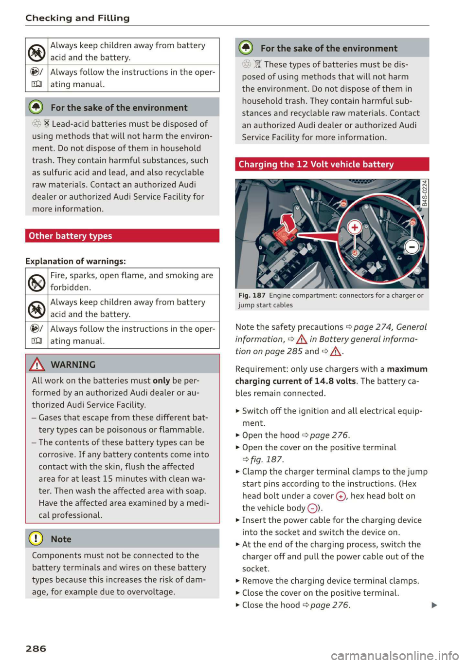
Fig. 187 Engine compartment: connectors for a charger or
jump start cables
Note the safety precautions > page 274, General
information, > /\ in Battery general informa-
tion on page 285 and > /\.
Requirement: only use chargers with a maximum
charging current of 14.8 volts. The battery ca-
bles remain connected.
> Switch off the ignition and all electrical equip-
ment.
> Open the hood > page 276.
> Open the cover on the positive terminal
> fig. 187.
> Clamp the charger terminal clamps to the jump
start pins according to the instructions. (Hex
head bolt under a cover (), hex head bolt on
the vehicle body ©).
> Insert the power cable for the charging device
into the socket and switch the device on.
> At the end of the charging process, switch the
charger off and pull the power cable out of the
socket.
> Remove the charging device terminal clamps.
> Close the cover on the positive terminal.
> Close the hood > page 276.
Page 289 of 360
4N0012721BD
Checking and Filling
AN WARNING
— Never connect a charging cable or jump
start cable directly to the 12 Volt vehicle
battery. Only use the connections in the en-
gine compartment > page 286.
— A highly explosive mixture of gases can form
when charging batteries. Only charge the
battery in well-ventilated areas.
— A drained battery can freeze at tempera-
tures around 32 °F (0 °C). Do not charge or
use a frozen or thawed battery. If ice forms,
the battery housing can crack and battery
electrolyte can leak out, which increases the
risk of an explosion and chemical burns.
Contact an authorized Audi dealer or author-
ized Audi Service Facility for more informa-
tion.
— Do not connect or disconnect the charging
cable while charging because this increases
the risk of an explosion.
@) Tips
Read all of the manufacturer's instructions
for the charger before charging the battery.
Windshield washer
system
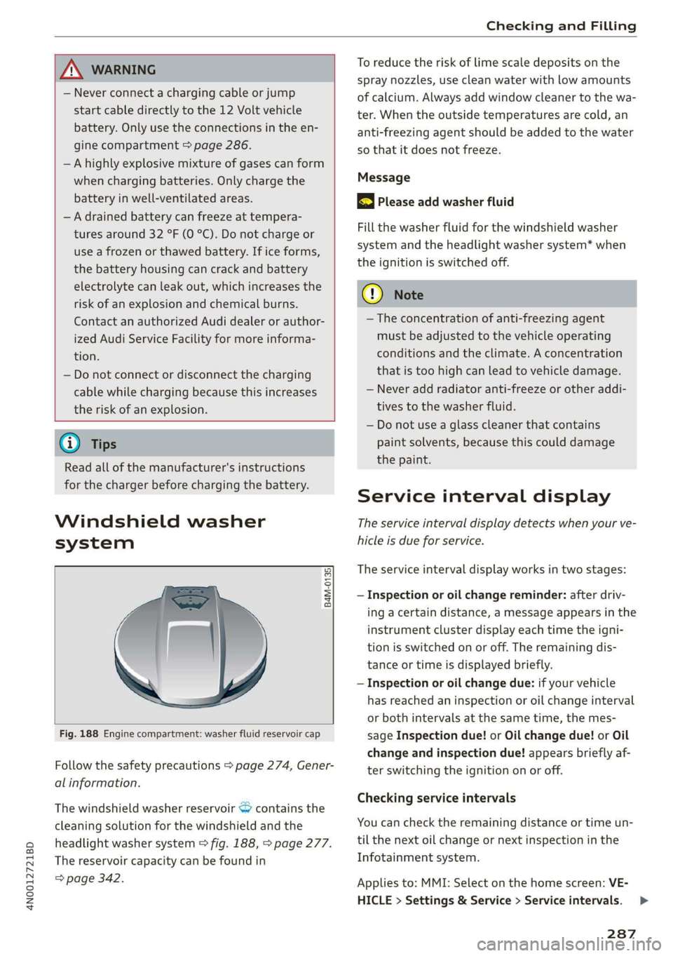
B4M-0135,
Fig. 188 Engine compartment: washer fluid reservoir cap
Follow the safety precautions > page 274, Gener-
al information.
The windshield washer reservoir > contains the
cleaning solution for the windshield and the
headlight washer system > fig. 188, > page 277.
The reservoir capacity can be found in
=> page 342.
To reduce the risk of lime scale deposits on the
spray nozzles, use clean water with low amounts
of calcium. Always add window cleaner to the wa-
ter. When the outside temperatures are cold, an
anti-freezing agent should be added to the water
so that it does not freeze.
Message
gS Please add washer fluid
Fill the washer fluid for the windshield washer
system and the headlight washer system* when
the ignition is switched off.
() Note
—The concentration of anti-freezing agent
must be adjusted to the vehicle operating
conditions and the climate. A concentration
that is too high can lead to vehicle damage.
— Never add radiator anti-freeze or other addi-
tives to the washer fluid.
— Do not use a glass cleaner that contains
paint solvents, because this could damage
the paint.
Service interval display
The service interval display detects when your ve-
hicle is due for service.
The service interval display works in two stages:
— Inspection or oil change reminder: after driv-
ing a certain distance, a message appears in the
instrument cluster display each time the igni-
tion is switched on or off. The remaining dis-
tance or time is displayed briefly.
— Inspection or oil change due: if your vehicle
has reached an inspection or oil change interval
or both intervals at the same time, the mes-
sage Inspection due! or Oil change due! or Oil
change and inspection due! appears briefly af-
ter switching the ignition on or off.
Checking service intervals
You can check the remaining distance or time un-
til the next oil change or next inspection in the
Infotainment system.
Applies to: MMI: Select on the home screen: VE-
HICLE > Settings & Service > Service intervals.
287
>
Page 310 of 360

Wheels
changing or replacing a tire on your vehicle
=> page 308. The tire pressure monitoring system
only monitors the tire pressure you have stored.
Refer to the tire pressure label for the recom-
mended tire pressure for your vehicle
=> page 299, fig. 192.
Tire tread circumference and vibration character-
istics can change and cause a tire pressure warn-
ing if:
— The tire pressure in one or more tires is too low
— The tires have structural damage
— The tire was replaced or the tire pressure was
changed and it was not stored > page 308
— Tires that are only partially used are replaced
with new tires
Indicator lights
® - Loss of pressure in at least one tire > A\.
Check the tires and replace or repair if necessary.
Check and correct the pressures of all four tires
and store the pressure again > page 308.
is (Tire Pressure Monitoring System) Tire pres-
sure: malfunction! See owner's manual. If fi
appears after switching the ignition on or while
driving and the @ indicator light in the instru-
ment cluster blinks for approximately one minute
and then stays on, there is system malfunction.
Try to store the correct tire pressures
= page 308. In some cases, you must drive for
several minutes after storing the pressures until
the indicator light turns off. If the indicator light
does turn off or turns on again after a short peri-
od of time, drive to an authorized Audi dealer or
authorized Audi Service Facility immediately to
have the malfunction corrected.
ZA WARNING
— If the tire pressure indicator appears in the
display, reduce your speed immediately and
avoid any hard steering or braking maneu-
vers. Stop as soon as possible and check the
tires and their pressure.
— The driver is responsible for maintaining the
correct tire pressure. You must check the
tire pressure regularly.
— Under certain conditions (such as a sporty
driving style, winter conditions, or unpaved
308
roads), the tire pressure monitoring system
indicator may be delayed.
@ Tips
—The tire pressure monitoring system can al-
so stop working when there is an ESC mal-
function.
— Using snow chains may result in a system
malfunction.
—The tire pressure monitoring system in your
Audi was calibrated with “Audi Original
Tires” > page 296. Using these tires is rec-
ommended.
Storing tire pressures
Applies to: vehicles with Tire Pressure Monitoring System
If the tire pressure changes or a tire is replaced,
it must be confirmed in the MMI.
> Before storing the tire pressures, make sure the
tire pressures in all four tires meet the speci-
fied values and are adapted to the load
=> page 299.
> Switch the ignition on.
> Applies to: MMI: Select on the home screen:
VEHICLE > Settings & Service > Tire pressure
monitoring > Store tire pressure > Yes, store
now.
@ Tips
Do not store the tire pressures if snow chains
are installed.
Page 312 of 360

Care and cleaning
height and width of the inside of the car
wash.
ZA WARNING
—To reduce the risk of accidents, only wash
the vehicle when the ignition is off and fol-
low the instructions from the car wash oper-
ator.
—To reduce the risk of cuts, protect yourself
from sharp metal components when wash-
ing the underbody or the inside of the wheel
housings.
— After washing the vehicle, the braking effect
may be delayed due to moisture on the
brake rotors or ice in the winter. This in-
creases the risk of an accident. The brakes
must be dried with a few careful brake appli-
cations.
—To reduce the risk of paint damage, do not
wash the vehicle in direct sunlight.
—To reduce the risk of damage, do not wash
decorative decals* with a pressure washer.
—To reduce the risk of damage to the surface,
do not use insect removing sponges, kitchen
sponges, or similar items.
— When washing matte finish painted vehicle
components:
— To reduce the risk of damage to the sur-
face, do not use polishing agents or hard
wax.
— Never use protective wax. It can destroy
the matte finish effect.
@) Note — Do not place any stickers or magnetic
signs on vehicle components painted with
matte finish paint. The paint could be
damaged when the stickers or magnets
are removed.
— If you wash the vehicle in an automatic car
wash, you must fold the exterior mirrors in
to reduce the risk of damage to the mirrors.
Power folding exterior mirrors* must only
be folded in and out using the power folding @) For the sake of the environment
function.
—To reduce the risk of damage to the rims
and tires, compare the width between the
wheels on your vehicle with the distance be-
tween the guide rails in the car wash.
—To reduce the risk of damage, compare the
height and width of your vehicle with the
Only wash the vehicle in facilities specially de-
signed for that purpose. This will reduce the
risk of dirty water contaminated with oil from
entering the sewer system.
Cleaning and care information
When cleaning and caring for individual vehicle are not listed, consult an authorized Audi dealer
components, refer to the following tables. The or authorized Audi Service Facility. Also follow
information contained there is simply recommen- __ the information found in > A.
dations. For questions or for components that
Exterior cleaning
Component Situation Solution
Windshield wiper | Deposits Soft cloth with glass cleaner > page 69
blades
Headlights/ Deposits Soft sponge with a mild soap solution®
Tail lights
Sensors/ Deposits Sensors: soft cloth with a solvent-free cleaning solution
camera lenses Camera lenses: soft cloth with an alcohol-free cleaning sol-
ution
Snow/ice Hand brush/solvent-free de-icing spray >
310
Page 320 of 360

Emergency assistance
Setting up the tire mobility kit
> Open the cover @) on the compressor”)
> fig. 196.
> Remove the connector () and pressure hose (5)
from the housing.
> Connect the compressor pressure hose © to
the flange © on the tire sealant bottle @).
> Insert the sealant bottle with the flange at the
bottom into the opening @) on the compressor
cover or the top side of the compressor hous-
ing.
> Remove the valve cap from the faulty tire.
> Install the filler hose @) on the valve (7)
> fig. 197.
> Connect the plug @) > fig. 196 to an outlet in
the vehicle.
> Switch the ignition on.
Inflating a tire
> Move the switch (8) > fig. 197 on the compres-
sor into position I.
> Inflate the tire to between 29 psi (200 kPA)
and 36 psi (250 kPA) and read the pressure on
the gauge.
> If this tire pressure is not reached, remove the
filler hose. Drive slowly approximately 33 feet
(10 m) forward or in reverse so that the sealant
can be distributed in the tire. Inflate the tire
again > A\.
ZA\ WARNING
— Read and follow the manufacturer's safety
precautions on the compressor and in the in-
structions on the bottle of sealant.
— Ifa tire pressure of 29 psi (200 kPA) cannot
reached after inflating for 6 minutes, then
the tire is too severely damaged. Do not con-
tinue driving.
— If the tire cannot be repaired with the tire
sealant, see an authorized Audi dealer or au-
thorized Audi Service Facility for assistance.
1) The compressor may look different. However, the way it is
operated is generally the same.
318
G) Tips
Do not operate the compressor for more than
six minutes continuously, or it can overheat.
Once the compressor has cooled, you can con-
tinue to use it.
fey cata]
Applies to: vehicles with tire mobility kit
> Affix the sticker that says "max. 50 mph (max.
80 km/h)" that is provided with the tire mobili-
ty kit within the driver's field of vision.
> Stop the vehicle after driving for about 10 mi-
nutes and check the tire pressure.
> If the tire pressure is lower than 19 psi (130
kPA), then the tire is too severely damaged. Do
not continue driving.
A WARNING
Pay attention to the following after repairing
the tire:
— Do not drive faster than 50 mph (80 km/h).
— Avoid hard acceleration or braking and driv-
ing fast around curves.
— The vehicle may become more difficult to
control.
— If the tire is too severely damaged, see an
authorized Audi dealer or authorized Audi
Service Facility for assistance.
@) For the sake of the environment
You can give the used tire sealant bottle to an
authorized Audi dealer or authorized Audi
Service Facility for disposal.
(i) Tips
Remember to obtain a new bottle of sealant
from an authorized Audi dealer or authorized
Audi Service Facility after repairing a tire.
Page 321 of 360
4N0012721BD
Emergency assistance
Replacing wheels
You must complete the preparation before
changing a tire.
> Read and follow the important safety precau-
tions > page 316.
> Set the parking brake.
> Select the “P” position.
> When towing a trailer: disconnect the trailer
from your vehicle.
> Lay out the vehicle tool kit > page 316 and the
spare tire > page 322.
> Applies to: MMI: Select on the home screen:
VEHICLE > Settings & Service > Air suspen-
sion: wheel change.
> Switch the ignition off.
Z\ WARNING
The vehicle must also be secured to prevent it
from rolling when using the vehicle jack”. Use
suitable objects to block the front and back of
the wheel that is diagonal from the wheel
Removing the caps
with the flat tire.
B4L-1337
&
[
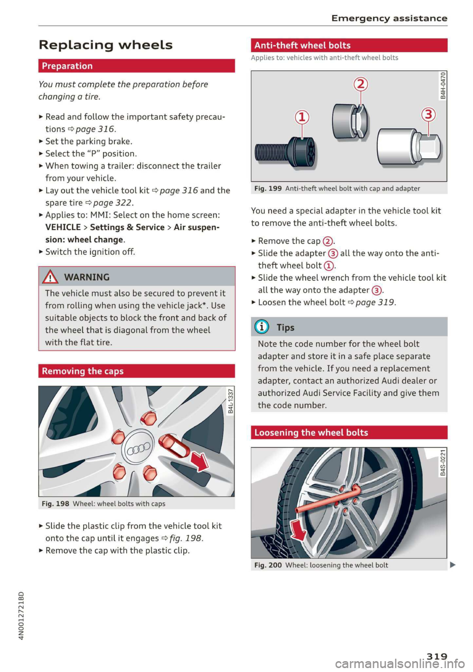
Fig. 198 Wheel: wheel bolts with caps
> Slide the plastic clip from the vehicle tool kit
onto the cap until it engages > fig. 198.
> Remove the cap with the plastic clip.
Anti-theft wheel bolts
Applies to: vehicles with anti-theft wheel bolts
i
> all
Fig. 199 Anti-theft wheel bolt with cap and adapter
B4H-0470
v
You need a special adapter in the vehicle tool kit
to remove the anti-theft wheel bolts.
>» Remove the cap @).
> Slide the adapter @) all the way onto the anti-
theft wheel bolt @.
» Slide the wheel wrench from the vehicle tool kit
all the way onto the adapter @).
> Loosen the wheel bolt > page 319.
@) Tips
Note the code number for the wheel bolt
adapter and store it in a safe place separate
from the vehicle. If you need a replacement
adapter, contact an authorized Audi dealer or
authorized Audi Service Facility and give them
the code number.
Loosening the wheel bolts
B4S-0221
Fig. 200 Wheel: loosening the wheel bolt
319
Page 326 of 360

Emergency assistance
4. Attach the other end of the negative cable
(black) to the jump-start pin @) on the vehi-
cle.
Starting the engine
> Start the engine in the vehicle giving the charge
and let it run at idle.
> Now start the engine in your vehicle, which has
the
drained battery.
> If the engine does not start, stop the starting
procedure after 10 seconds and then repeat it
after approximately 30 seconds.
> Turn on the rear window defogger in your vehi-
cle in order to reduce any voltage peaks that
may occur when disconnecting the jump start
cables. The headlights must be switched off.
> With the engines running, remove the cables in
reverse order of the way they were installed.
> Close the red cover on the positive terminal.
ZA WARNING
— Never connect the jump start cable directly
to your vehicle battery. Only use the connec-
tions in the engine compartment.
— Do not touch the non-insulated parts of the
terminal clamps. The cable must also not
come into contact with vehicle components
that conduct electricity when it is connected
to the positive vehicle battery terminal. This
can cause a short circuit.
— The plugs on the battery cells must not be
opened.
— Keep ignition sources (such as open flames,
burning cigarettes, etc.) away from the vehi-
cle batteries to reduce the risk of an explo-
sion.
— Route the jump start cables so they cannot
get caught in the moving parts in the other
vehicle's engine compartment.
@ Note
Please note that the connecting process previ-
ously described for the jump start cables is in-
tended for when your vehicle is being jump
started.
324
G) Tips
Make sure that the connected jump start ca-
bles have sufficient contact with metal.
Towing
General information
You should only perform the steps that follow if
you have the necessary tools and technical ex-
pertise.
Towing requires a certain amount of practice.
Audi recommends contacting a towing company
to have the vehicle transported.
You should only have your vehicle towed by an-
other vehicle when disabled in exceptional cir-
cumstances. Inexperienced drivers should not
tow.
Notes on towing
When the engine is stopped, the transmission
will not be sufficiently lubricated if traveling at
high speeds and long distances:
— The maximum permitted towing speed is 30
mph (50 km/h).
— The maximum permitted towing distance is 30
miles (50 km).
Additional information on towing with a tow
truck
The vehicle may only be towed with the front axle
raised. Do not wrap any chains or cables around
the brake lines.
Tow bar and towing cable
The vehicle can be towed with a tow bar or tow-
ing cable. Both drivers should be familiar with
the
special considerations when towing, especial-
ly when using a towing cable.
Always make sure the traction force does not ex-
ceed the permitted level and there are no shock
loading conditions. There is always the risk of the
coupling becoming overloaded when driving off-
road.
For the most safety and security, drive with a tow
bar. You should use a towing cable only ifatow >
Page 327 of 360

4N0012721BD
Emergency assistance
bar is not available. Use a towing cable made of
synthetic elastic cable similar elastic material.
Z\ WARNING
— Towing highly increases the risk of an acci-
dent, for example from colliding with the
towing vehicle.
— To reduce the risk of an accident, do not al-
low anyone to remain inside the vehicle
when it is being transported by a tow truck
or a special transporter.
@) Note
— If normal towing is not possible, for exam-
ple if the transmission is faulty or if the
towing distance is greater than 30 miles
(50 km), then transport the vehicle on a
special carrier.
— If the vehicle is towed by a tow truck at the
axle that is not permitted, this can cause se-
vere damage to the transmission.
— The vehicle must not be tow started for
technical reasons.
@ Tips
— If the power supply is interrupted, then it
will not be possible to move the selector
lever out of the "P" position. The parking
lock must be released using the emergency
release before towing the vehicle
=> page 116.
— Switch Audi pre sense* off > page 185 when
loading the vehicle onto a vehicle carrier,
train, ship, or other type of transportation,
or when towing the vehicle. This can prevent
an undesired intervention from the pre
sense* system.
— Follow the local legal regulations for tow-
ing.
Read and follow the important information under
=> page 324.
Preparations
> Only secure the towing cable or tow bar at the
designated towing loops > page 325,
=> page 326.
> Make sure the towing cable is not twisted. Oth-
erwise it could disconnect from the towing loop
while towing.
> Switch the emergency flashers on in both
vehicles > page 64. However, do not do this if it
prohibited by law.
Towing vehicle (front)
> Only start to drive when the towing cable is
taut.
> Press the brake pedal very carefully.
> Avoid sudden braking or driving maneuvers.
Vehicle being towed (rear)
> Make sure the ignition is switched on so that
the steering wheel is not locked and so that you
can use the turn signals, the horn, and the
windshield wipers if needed > A\.
> Switching it off before the vehicle has stopped
may impair the function of the brake booster
and power steering. You would then need to
use more force to steer and brake the vehicle.
> Release the parking brake > page 124.
> Select the “N” selector lever position.
> Make sure the towing cable is always taut.
ZA WARNING
Never tow a vehicle using a tow bar or towing
cable if the vehicle does not have electrical
power.
Front towing loop
BFV-0305
Fig. 207 Front bumper: installing the towing loop
325
Page 329 of 360
4N0012721BD
Fuses and bulbs
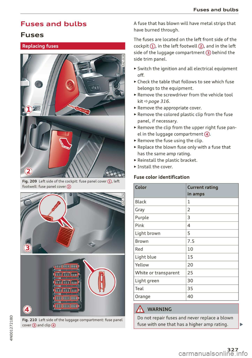
Fig. 209 Left side of the cockpit: fuse panel cover (), left
footwell: fuse panel cover @)
Fig. 210 Left side of the luggage compartment: fuse panel
cover @) and clip @)
A fuse that has blown will have metal strips that
have burned through.
The fuses are located on the left front side of the
), in the left footwell @), and in the left
side of the luggage compartment (8) behind the
side trim panel.
> Switch the ignition and all electrical equipment
off.
> Check the table that follows to see which fuse
belongs to the equipment.
> Remove the screwdriver from the vehicle tool
kit > page 316.
> Remove the appropriate cover.
> Remove the colored plastic clip from the fuse
panel, if necessary.
> Remove the clip from the upper right fuse pan-
el in the luggage compartmen
> Remove the fuse using the clip.
> Replace the blown fuse only with a fuse that
has the same amp rating.
> Reinstall the plastic bracket.
> Install the cover.
Fuse color identification
Color Current rating
in amps
Black 1
Gray 2
Purple 3
Pink 4
Light brown 5
Brown 45)
Red 10
Light blue 15
Yellow 20
White or transparent [25
Light green 30
Teal 35
Orange 40
ZA\ WARNING
Do not repair fuses and never replace a blown
fuse with one that has a higher amp rating.
327