jack points AUDI A8 2020 Owners Manual
[x] Cancel search | Manufacturer: AUDI, Model Year: 2020, Model line: A8, Model: AUDI A8 2020Pages: 360, PDF Size: 95.38 MB
Page 322 of 360

Emergency assistance
>» Slide the wheel wrench from the vehicle tool kit
all the way onto the wheel bolt).
> Turn the wheel bolt approximately one turn to
the left. To achieve the required torque, hold
the end of the wheel wrench. If the wheel bolt
will not loosen, press carefully on the wheel
wrench with your foot. Hold onto the vehicle se-
curely while doing this and make sure your foot-
ing is stable.
ZA WARNING
To reduce the risk of an accident, only loosen
the wheel bolts gently one turn before raising
the vehicle with the vehicle jack*.
Raising the vehicle
Applies to: vehicles with vehicle jack
> Find the marking on the sill that is closest to
the tire that will be changed > fig. 201. Behind
the marking, there is a lifting point on the side
sill for the vehicle jack.
> Turn the vehicle jack located under the lifting
point on the sill to raise the jack until its arm @
=> fig. 202 is located under the designated plas-
tic mount.
> Align the vehicle jack so the arm (@) engages in
the designated Lifting point in the door sill and
the movable base (2) lies flat on the ground.
The base @) must be directly under the mount-
ing point @.
> Continue raising the vehicle jack until the wheel
lifts off the ground slightly.
RAZ-0257,
Fig. 202 Sill: positioning the vehicle jack
> Place the vehicle jack from the vehicle tool kit
ona firm surface. Use a flat, stable support if
necessary. On a slippery surface such as tile,
you should use a non-slip pad such as a rubber
mat > /A\.
D_ You need the matching adapter in order to loosen and
tighten anti-theft wheel bolts* > page 319.
320
Z\ WARNING
—To reduce the risk of injury, make sure no
one is in the vehicle before raising it.
— Make sure the vehicle jack is stable. The risk
of injury is increased when the ground is
slippery or soft, because the vehicle jack
could slide or sink.
— Only raise your vehicle with the vehicle jack
provided by the factory. If you use a vehicle
jack designed for another vehicle, your vehi-
cle could slip and cause injury.
— Position the vehicle jack only at the desig-
nated mounting points on the side sill and
align the jack. Otherwise, the vehicle jack
could slip and cause an injury if it does not
have sufficient hold on the vehicle.
—To reduce the risk of injury, do not raise any
other vehicles or other loads using the vehi-
cle jack provided by the factory.
— Changes in temperature or load can affect
the height of the vehicle.
— To reduce the risk of an accident, never start
the engine when the vehicle is raised.
—To reduce the risk of injury, no work should
be performed under the vehicle while it is
raised.
Page 323 of 360

4N0012721BD
Emergency assistance
@) Note
Do not Lift the vehicle by the sill. Position the
vehicle jack only at the designated mounting
points on the side sill. Otherwise, your vehicle
could be damaged.
Removing and installing a wheel
@ g + “
0 oO
B8K-1477
Fig. 204 Wheel: alignment pin in the top hole
Removing a wheel
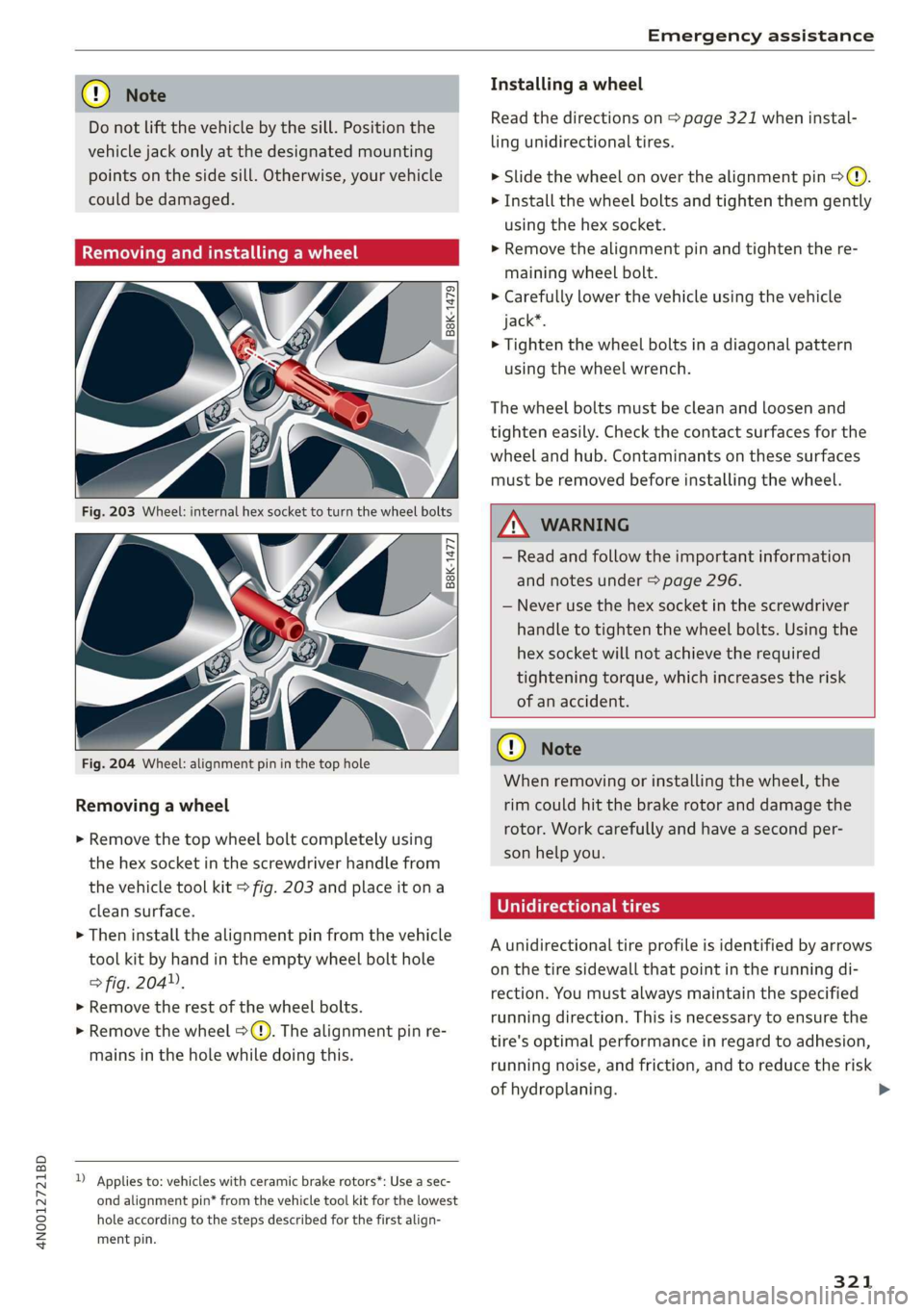
> Remove the top wheel bolt completely using
the hex socket in the screwdriver handle from
the vehicle tool kit > fig. 203 and place it ona
clean surface.
> Then install the alignment pin from the vehicle
tool kit by hand in the empty wheel bolt hole
> fig. 204”,
> Remove the rest of the wheel bolts.
> Remove the wheel >(). The alignment pin re-
mains in the hole while doing this.
D Applies to: vehicles with ceramic brake rotors*: Use a sec-
ond alignment pin* from the vehicle tool kit for the lowest
hole according to the steps described for the first align-
ment pin.
Installing a wheel
Read the directions on > page 321 when instal-
ling unidirectional tires.
> Slide the wheel on over the alignment pin >@.
> Install the wheel bolts and tighten them gently
using the hex socket.
> Remove the alignment pin and tighten the re-
maining wheel bolt.
> Carefully lower the vehicle using the vehicle
jack*.
> Tighten the wheel bolts in a diagonal pattern
using the wheel wrench.
The wheel bolts must be clean and loosen and
tighten easily. Check the contact surfaces for the
wheel and hub. Contaminants on these surfaces
must be removed before installing the wheel.
Z\ WARNING
— Read and follow the important information
and notes under > page 296.
— Never use the hex socket in the screwdriver
handle to tighten the wheel bolts. Using the
hex
socket will not achieve the required
tightening torque, which increases the risk
of an accident.
@) Note
When removing or installing the wheel, the
rim could hit the brake rotor and damage the
rotor. Work carefully and have a second per-
son help you.
Unidirectional tires
A unidirectional tire profile is identified by arrows
on the tire sidewall that point in the running di-
rection. You must always maintain the specified
running direction. This is necessary to ensure the
tire's optimal performance in regard to adhesion,
running noise, and friction, and to reduce the risk
of hydroplaning. >
321
Page 351 of 360

4N0012721BD
Intermittent mode (windshield wipers) ..... 68
International travel...............0000. 221
Internet
refer toconnect.............000e ee eee 216
Internet radio
refer to Online radio...............04. 245
Intersection assistant...............00. 189
TOniZer’. « excssm « © wore» » mince nu eae & 7 omnes 106
iPhone
refer to Audi music interface....... 253, 254
J
Jump starting....................0.00. 322
K
KEY sencaia ss 5 casmens 6 saneeue «x comes +H om wo 43,47
Convenience opening and closing......... 54
Key
replacement ..........:ee eee een eee 47
Mechanical key...........0 0000000 ee eee 47
Not recognized...............00 ee cae 112
PANIC K@V's « « come « eee a 5 poem 2 9 come be ee 47
Replacing the battery..........c0eeeeee 49
Unlocking and locking............-...0- 48
Nehicl@ code escs s gases ¥ news so eee + + eee 47
Key USEN's = syns « 2 sews + 2 saeG § totes be ee 42
Kick-down .. 0.0... cee eee eee eee 116
L
Lane assist
refer to Lane departure warning......... 180
refer to Lane guidance.............44 180
Lane departure warning................. 180
Cleaning the camera area.............. 310
Lane guidance...............0.--00 eee 174
Baprtimer’s exci a 2 ewer 3 0 vesves 6 v aman oo cave 162
Evaluating. ............ 00sec ee eae 163
SEALING ss + exam ys Ke a 2 HOG 8 eee so 8 162
Laser lighting’ + = xcas 4 « sean x shee cB eee 62
Laserscanner........ 6. cece eee ee eee 155
Cleaning = ¢ segs + © neces 3s ees xe pee 311
LATCH (securing child safety seats)......... 93
Leather care and cleaning............... 312
Legal information
License subscriptions................. 269
Software information's . 6 sis. wae ee oe 269
Software:licensesiiic x « swcve wo sane w staves 2 269
Version information..............000- 269
Legsupport.....................00000. 77
License plate bracket................... 338
Lifting points (vehicle jack).............. 320
Light/rain sensor
Headlights .......... cece eee eee eee 60
Intermittent mode (windshield wipers) .... 68
Lighting
EXteriOt’: « sess = 4 eee gs eee s 2 ream es eee 60
FM GORIOR aisins sv arava so aworane % @ asewave 9 & aoavaun a 8 64
LIQHtS « issn so wmv oo eine + & on a 2 emNETS 8 oo 60
Lights on the charging port
refer to Charging display............... 140
Listening to music
referto Media...............0-.. 250, 255
Load... 6... eee 342
Locking
and unlocking
By remote control..............-.00005 48
Using the lock cylinder................. 46
With the convenience key............045 48
Low beam headlights.................0.. 60
Luggage compartment................. 100
Valet parking... . 0... cece eee eee eee 56
also refer to Luggage compartment..... 100
Luggage compartment lid................ 53
Closing bUttOM ss <= gaws ¢ ¢ come < oes = Hee 51
General information ............0000008 50
Mechanically unlocking................. 52
Opening and closing...............000- 50
Opening and closing with foot motion..... 52
Opening from the inside in an emergency... 53
Power opening and closing.............. 51
Lumbar support.............-..0-005 73,76
M
Maintenance... ..... ccc e eee eee ee 336
Maintenance intervals.................. 287
Malfunction Indicator Lamp (MIL)........ 274
Manually releasing the charging connector. 142
Manually releasing the charging port door.. 142
Manual shifting’: « = ss 2s eae 2 2 oso 2 oe 115
Map
Changing thersale nice << sisi +o cusane +o ar 230
Display. .... 0... ee eee eee 232
349