AUDI E-TRON 2019 Owners Manual
Manufacturer: AUDI, Model Year: 2019, Model line: E-TRON, Model: AUDI E-TRON 2019Pages: 310, PDF Size: 81.91 MB
Page 121 of 310
4KE012721BB
High-voltage system
> Tighten the screw (3) using the screwdriver pro-
vided.
ZA\ WARNING
— Note the warnings for charging > A in
Charging on page 109.
— Before switching the power cable, always
unplug the power cable from the socket.
— Only change cables in a dry environment.
— The Audi charging system may only be used
as a complete unit consisting of the power
cables, the control unit, and the vehicle ca-
ble. We recommend using only cables ap-
proved by Audi.
i) Tips
The power cable with the power connector for
industrial sockets and the Audi charging sys-
tem control unit are designed to work togeth-
er. Changing the power cable to another con-
nector type may reduce the available charging
power of the entire system.
Wall mount clip
Applies to: vehicles with wall mount clip
RAZ-0638
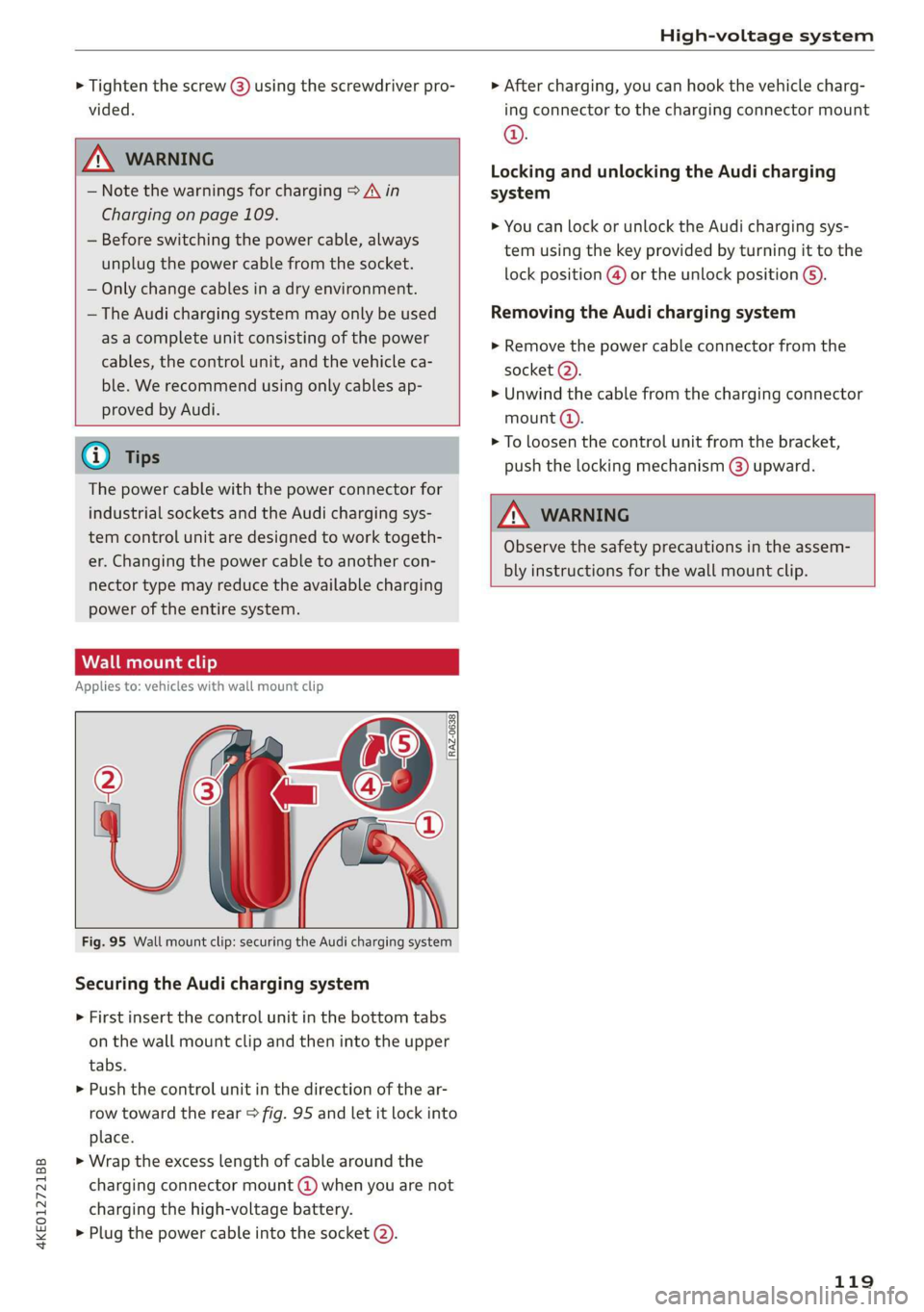
Fig. 95 Wall mount clip: securing the Audi charging system
Securing the Audi charging system
> First insert the control unit in the bottom tabs
on the wall mount clip and then into the upper
tabs.
> Push the control unit in the direction of the ar-
row toward the rear > fig. 95 and let it lock into
place.
> Wrap the excess length of cable around the
charging connector mount @) when you are not
charging the high-voltage battery.
> Plug the power cable into the socket (2).
> After charging, you can hook the vehicle charg-
ing connector to the charging connector mount
©.
Locking and unlocking the Audi charging
system
> You can lock or unlock the Audi charging sys-
tem using the key provided by turning it to the
lock position @) or the unlock position 6).
Removing the Audi charging system
> Remove the power cable connector from the
socket (2).
» Unwind the cable from the charging connector
mount @).
> To loosen the control unit from the bracket,
push the locking mechanism (@) upward.
ZA\ WARNING
Observe the safety precautions in the assem-
bly instructions for the wall mount clip.
119
Page 122 of 310
Trailer towing
Trailer towing
Driving with a trailer
ere eleurl lela)
Your vehicle is primarily intended for transport-
ing people and luggage. However, if you drive
with a trailer, follow the technical requirements,
the operation and driving tips, and the legal reg-
ulations.
Driving with a trailer affects the vehicle's energy
usage, performance, and wear. It also requires
higher concentration from the driver.
ZA WARNING
Do not transport any people in a trailer due to
the risk of fatal injury.
Technical requirements
Certain requirements must be met when towing
a trailer.
Trailer hitch
Only use a trailer hitch with a removable ball
hitch mount and ball hitch. The trailer hitch must
be permitted for the vehicle, the trailer and the
permitted total weight of the trailer being
pulled. Above all, it must be securely and safely
attached to the vehicle trailer.
Never mount a trailer hitch on the bumper. The
trailer hitch must be mounted in a way that does
not impair the function of the bumper. Do not
make any changes to the exhaust system and the
brake system.
Check regularly if the trailer hitch is securely
mounted. Always follow the instructions given by
the trailer hitch manufacturer.
Trailer brakes
If the trailer has its own brake system, then fol-
low the manufacturer specifications. However,
the brake system on the trailer must never be
connected to the vehicle brake system.
120
AN WARNING
— Never mount a "weight-distributing" or
"load-balancing" trailer coupler as the trailer
hitch. The vehicle was not designed for
these types of trailer hitches. The trailer
hitch can malfunction and the trailer can
break off from the vehicle.
— If the trailer is equipped with electronic
brakes, these brakes cannot be activated by
a factory-installed control system, which in-
creases the risk of an accident.
—To reduce the risk of injury, always remove
the ball hitch mount if no trailer is mount-
ed.
Oo} T-Te lalate mie as (olay
Towing capacity
The permitted towing capacity must not be ex-
ceeded under any circumstances > page 292.
You can drive up larger inclines if you are not us-
ing the maximum towing capacity.
The towing capacities given only apply to eleva-
tions up to 3,200 feet (1,000 m) above sea level.
As the elevation increases, the motor power de-
creases due to the decreasing air pressure. This
reduces the hill climbing ability and towing ca-
pacity. For every additional 3,200 ft (1,000 m),
the maximum permitted towing weight must be
reduced by approximately 10%. The permitted
towing weight is the combined weight of the
(loaded) vehicle and the (loaded) trailer.
Tongue weight
The maximum permitted tongue weight of the
trailer drawbar on the trailer hitch ball head must
not be exceeded.
Having the tongue weight too low affects the ve-
hicle's handling. For driving safety, always using
the maximum permitted tongue weight is recom-
mended, but not exceed it. Distributing the cargo
in the trailer correctly will help to achieve this
weight.
You can determine the tongue weight using a
tongue weight scale, a bathroom scale, or a pub-
lic weigh station, for example.
Page 123 of 310
4KE012721BB
Trailer towing
The permitted tongue weight of your vehicle can
be found in the vehicle documentation or in
=> page 292.
Load distribution
Poor cargo load and distribution can negatively
impact vehicle handling. Load the trailer based
on the following criteria as much as possible:
— Store objects in the vehicle luggage compart-
ment, if possible. The vehicle should always
carry the heaviest possible load and the trailer
should have the lightest possible load.
— Distribute the load in the trailer so that the
heavy objects are as close to the axle as possi-
ble.
— Secure objects so that they do not slide.
— Utilize the maximum permitted tongue weight
if possible.
Tires
Set the tire pressure on your vehicle for a “full
load”; see the tire pressure sticker > page 253. If
necessary, also adjust the tire pressure on the
trailer according to the manufacturer's specifica-
tions.
The trailer and the vehicle should be equipped
with winter tires when driving in winter tempera-
tures.
Outside mirrors
If you cannot see the traffic behind the trailer
with the standard exterior mirrors, then you
must attach additional exterior mirrors. Adjust
them so you have a sufficient visibility behind
you.
Exterior lighting
Follow the legal regulations for lighting on your
trailer that are applicable in the country where
you are operating the vehicle. Contact an author-
ized Audi dealer or authorized Audi Service Facili-
ty for more information.
Before you start driving, check all lighting equip-
ment on the trailer while it is hitched to the vehi-
cle.
The headlight range control automatically ad-
justs the light range of the headlights.
Safety chains
Make sure the safety chains are correctly applied
when pulling a trailer. The chains should hang
enough so that the trailer can drive around
curves. However, they must not touch the
ground.
Air suspension
The Audi drive select* comfort mode > page 98
must be selected before you adjust the tongue
weight on the trailer and hitch the trailer >@,
=> page 99.
For vehicles with a retrofitted trailer hitch, you
must switch on the air suspension trailer mode
manually.
Applies to: MMI: Select on the home screen: VE-
HICLE > Settings & Service > Air suspension:
trailer.
Switch it off again when you are no longer towing
a trailer.
When using carrier systems that are mounted di-
rectly on the trailer hitch ball head, you can also
switch trailer mode off manually.
If you must drive on roads that are in poor condi-
tion, you can raise the vehicle again after hitching
the trailer or after adjusting the tongue weight
> page 99.
You can also increase ground clearance by select-
ing the Audi drive select* offroad or allroad
modes > page 98.
Vehicle levels below the values set in the comfort
level will no Longer be available, even if you are
lowering the vehicle manually.
ZA WARNING
— Never turn off trailer mode while driving
when a trailer is hitched, because then the
restrictions for controlling the vehicle level
will be turned off.
— Driving with a trailer on unpaved roads when
the vehicle is raised may change the vehicle
handling. Adapt your speed.
121
Page 124 of 310
Trailer towing
— Note that the vehicle will lower automatical-
ly at certain speeds if you have lifted the
vehicle manually.
@) Note
— Select the Audi drive select* comfort mode.
Otherwise, the tongue load specified for
your vehicle will no longer be applicable.
— Attachments retrofitted on the vehicle may
cause damage, especially on the trailer
hitch ball head. In cases of damage, have
the function checked by an authorized Audi
dealer or authorized Audi Service Facility.
@ Tips
— Block the wheels with chocks when parking
on inclines if the trailer is loaded.
— Having the vehicle inspected between the
inspection intervals is recommended if you
tow a trailer frequently.
Driving with a trailer
Driving with a trailer requires extra caution.
Speed
Adhere to the legal speed limits. Follow the legal
regulations that are applicable in the country
where you are operating the vehicle.
As the speed increases, the driving stability of
the trailer decreases. Therefore you should not
exceed the maximum legal speed limit when
there are unfavorable road, weather, and/or wind
conditions. This especially applies when driving
downhill.
Hill
When you start driving uphill or downhill, trailers
may tilt or sway sooner than when driving ona
level surface. If small swaying movements have
already occurred, you can stabilize the trailer by
firmly braking immediately. Never try to
“straighten out” the trailer by accelerating.
122
Brakes
When using a trailer with overrun brakes, first
brake gently then quickly. This reduces the risk of
jerking while braking if the trailer wheels lock up.
ZA WARNING
Constant braking causes the brakes to over-
heat and can substantially reduce braking per-
formance, increase braking distance, or cause
complete failure of the brake system.
Page 125 of 310
4KE012721BB
Assist systems
Assist systems
General information
Sica eel delay
ZA WARNING
— As the driver, you are always completely re-
sponsible for all driving tasks. The assist
systems cannot replace the driver's atten-
tion. Give your full attention to driving the
vehicle, and be ready to intervene in the
traffic situation at all times.
— Activate the assist systems only if the sur-
rounding conditions permit it. Always adapt
your driving style to the current visual,
weather, road, and traffic conditions.
— Unexpected steering or braking interven-
tions may be initiated by the assist systems.
Note the information on storing luggage
items correctly > page 77.
— For the assist systems to be able to react
correctly, the function of the sensors and
cameras must not be restricted. Note the in-
formation on sensors and cameras
=>page 124 or > page 125.
G) Tips
— Pay attention to applicable local regulations
relating to driving tasks, leaving space for
emergency vehicles, vehicle distance, speed,
parking location, wheel placement, etc. The
driver is always responsible for following
the laws that are applicable in the location
where the vehicle is being operated.
— You can cancel a steering or braking inter-
vention by the system by braking or acceler-
ating noticeably, steering, or deactivating
the respective assist system.
— Always check the assist systems settings be-
fore driving. The settings could have been
changed, for example, by other drivers or if
another personal profile was used.
System limitations
ZA\ WARNING
—The use of an assist system cannot over-
come the natural laws of physics. A collision
cannot be prevented in certain circumstan-
ces.
— Warnings, messages, or indicator lights may
not be displayed or initiated on time or cor-
rectly, for example, if vehicles are approach-
ing very fast.
— Corrective interventions by the assist sys-
tems, such as steering or braking interven-
tions, may not be sufficient or they may not
occur. Always be ready to intervene.
@) Tips
— Due to the system limitations when detect-
ing the surrounding area, the systems may
warn or intervene unexpectedly or too late
in certain situations. The assist systems may
also interpret a driving maneuver incorrectly
and then warn the driver unexpectedly.
— The systems may not function as expected
in unusual driving situations, such as driving
offroad, on unpaved roads, on loose ground,
on inclines, or on grooves in the road.
— The systems may not function correctly in
unclear traffic situations, such as turning
lanes, exit ramps, construction zones, rises
or dips that obstruct visibility, intersections,
toll stations, or city traffic.
—In trailer mode, some assist systems may be
limited, may not react as usual, or may be
unavailable. Please refer to the instructions
for towing a trailer located in > page 120.
— If accessories have been mounted on the
steering wheel, the ability for the steering
systems to react may be limited.
123
Page 126 of 310
Assist systems
Surrounding area
detection
Sensor overview
RAZ-06T1
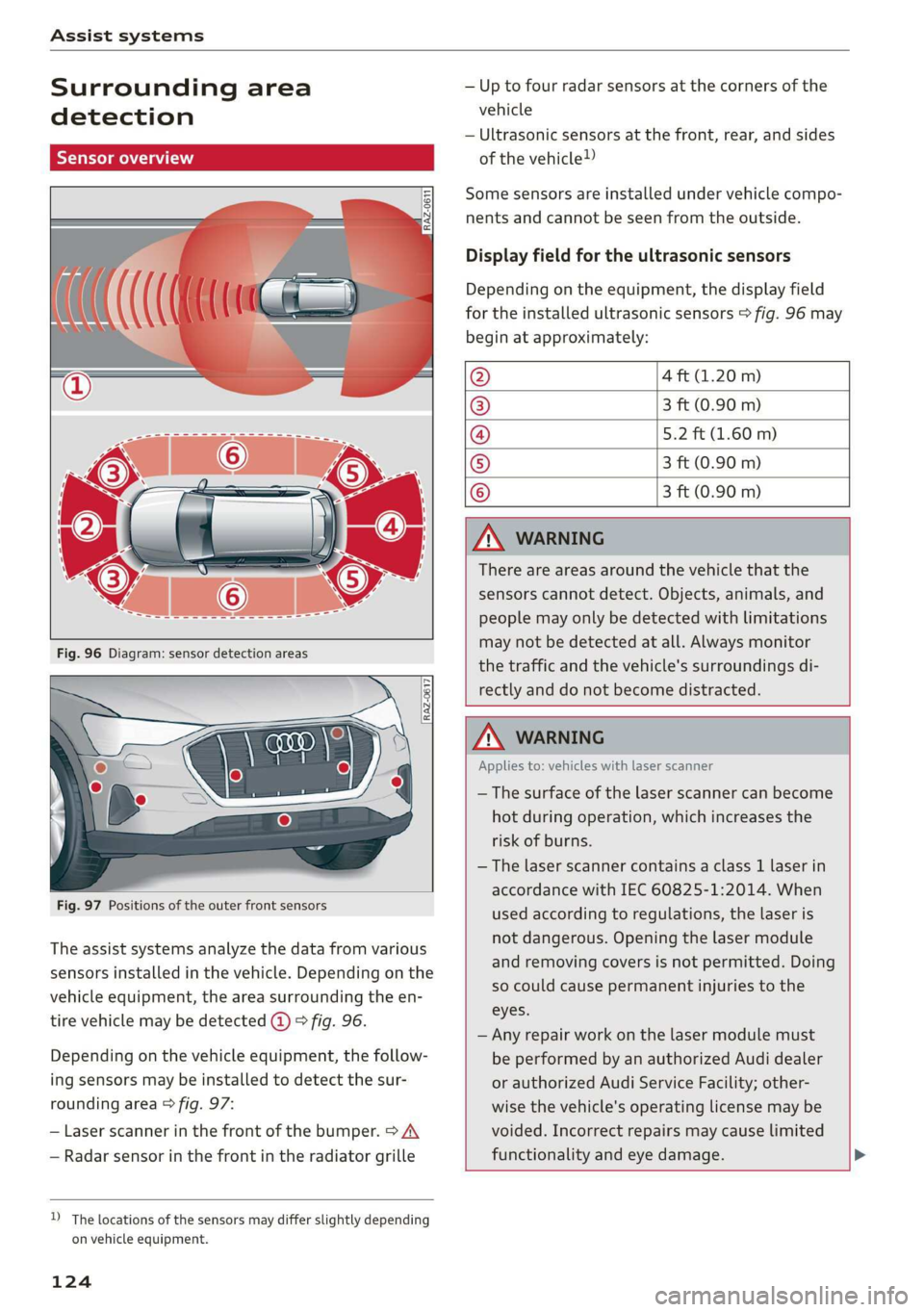
Fig. 97 Positions of the outer front sensors
The assist systems analyze the data from various
sensors installed in the vehicle. Depending on the
vehicle equipment, the area surrounding the en-
tire vehicle may be detected @ 9 fig. 96.
Depending on the vehicle equipment, the follow-
ing sensors may be installed to detect the sur-
rounding area > fig. 97:
— Laser scanner in the front of the bumper. > A\
— Radar sensor in the front in the radiator grille
D_ The locations of the sensors may differ slightly depending
on vehicle equipment.
124
— Up to four radar sensors at the corners of the
vehicle
— Ultrasonic sensors at the front, rear, and sides
of the vehicle!)
Some sensors are installed under vehicle compo-
nents and cannot be seen from the outside.
Display field for the ultrasonic sensors
Depending on the equipment, the display field
for the installed ultrasonic sensors > fig. 96 may
begin at approximately:
@ 4 ft (1.20 m)
® 3 ft (0.90 m)
@ 5.2 ft (1.60 m)
® 3 ft (0.90 m)
© 3 ft (0.90 m)
ZA\ WARNING
There are areas around the vehicle that the
sensors cannot detect. Objects, animals, and
people may only be detected with limitations
may not be detected at all. Always monitor
the traffic and the vehicle's surroundings di-
rectly and do not become distracted.
ZA WARNING
Applies to: vehicles with laser scanner
— The surface of the laser scanner can become
hot during operation, which increases the
risk of burns.
— The laser scanner contains a class 1 laser in
accordance with IEC 60825-1:2014. When
used according to regulations, the laser is
not dangerous. Opening the laser module
and removing covers is not permitted. Doing
so could cause permanent injuries to the
eyes.
— Any repair work on the laser module must
be performed by an authorized Audi dealer
or authorized Audi Service Facility; other-
wise the vehicle's operating license may be
voided. Incorrect repairs may cause limited
functionality and eye damage.
Page 127 of 310
Assist systems
4KE012721BB
Q) Note —The side area ©)* is detected and evaluated
when passing. There may have been
— Obstacles may disappear from the detection changes to the surrounding area after
area when approaching them, even if they switching the ignition off and on again, af-
were already detected. Under certain cir- ter opening the doors, or if the vehicle is left
cumstances, the detection and display of stationary for a period of time. In this case,
certain surfaces and objects may be limited: the area will appear black until the area has
— Items and objects above the coverage been detected and evaluated.
area, for example cars parked bumper-to- — Applies to: vehicles with laser scanner: The
bumper, half-open garage doors, or hang- possible emissions are below the threshold
ing objects that do not touch the ground for class 1 lasers.
— Low obstacles — For an explanation on conformity with the
— Thin or narrow objects, such as barrier FCC regulations in the United States and the
chains, foliage, poles or fences Industry Canada regulations, see
— Projecting objects, such as trailer draw => page 289.
bars
— Objects with certain surfaces and struc- Camera overview
tures, such as fabric
@ Tips
— The coverage areas of the sensors > fig. 96
are diagrams and do not represent a true-
to-scale image of the sensor ranges. The ra-
dar sensors are designed to detect the left
and right adjacent lanes when the road
lanes
are the normal width.
[RAZ-0271
— Make sure all the sensors are clean, free of
snow and ice, and are not covered by stick-
ers, deposits or any other obstructions, be-
cause this may impair the function of the
systems. Follow the information about
cleaning > page 263.
— The sensors can shift from an accident,
manual force, impacts, or from damage to
the radiator grill, bumper, wheel housing,
or underbody. Do not continue using the as-
sistance systems if the sensors have shifted,
because this is unsafe. Have an authorized
Audi dealer or authorized Audi Service Fa-
[RAZ-0212
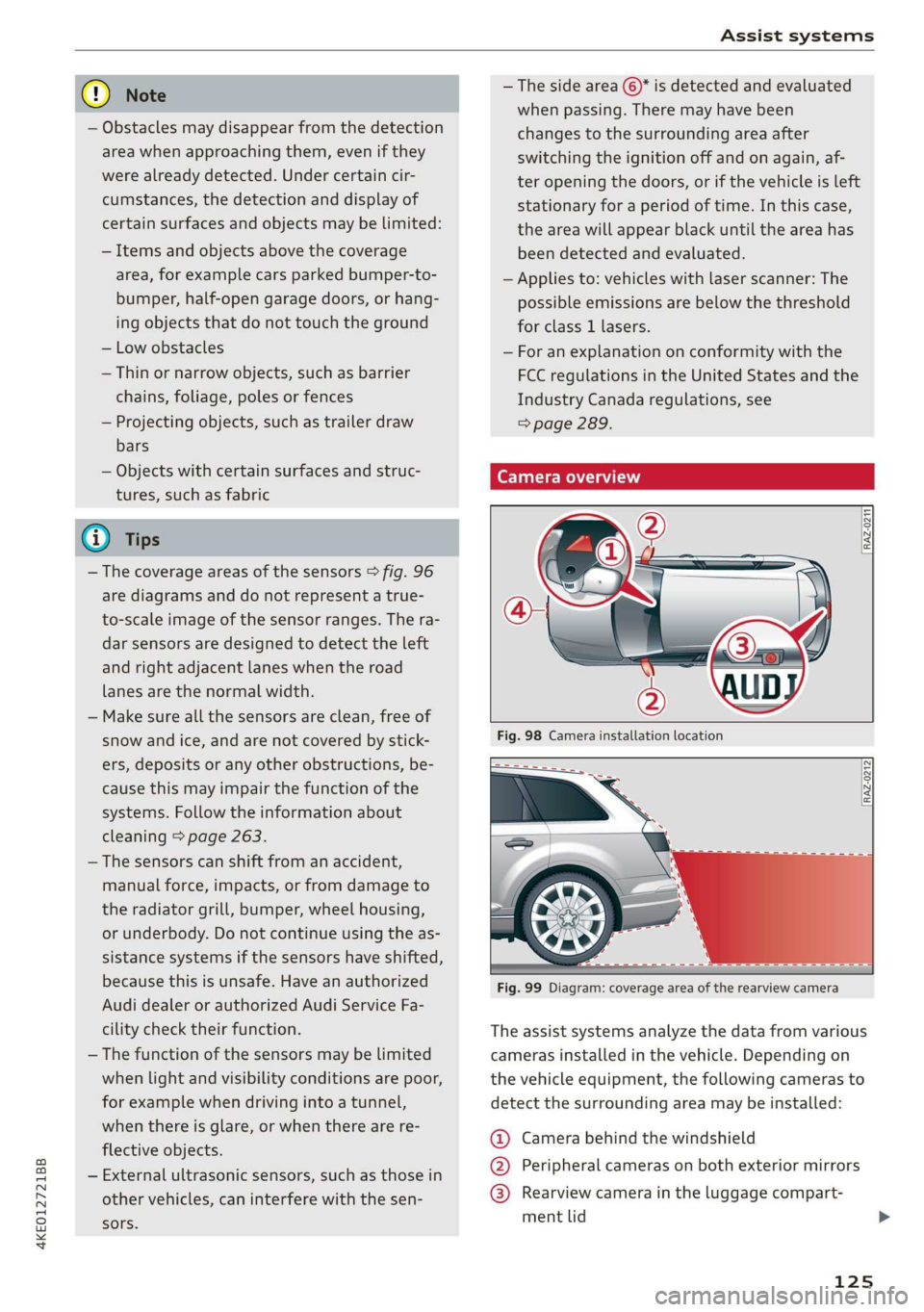
cility check their function. The assist systems analyze the data from various
— The function of the sensors may be limited cameras installed in the vehicle. Depending on
when light and visibility conditions are poor, the vehicle equipment, the following cameras to
for example when driving into a tunnel, detect the surrounding area may be installed:
when there is glare, or when there are re-
flective objects.
— External ultrasonic sensors, such as those in
other vehicles, can interfere with the sen-
sors.
@ Camera behind the windshield
@ Peripheral cameras on both exterior mirrors
@® Rearview camera in the luggage compart-
ment lid
125
Page 128 of 310
Assist systems
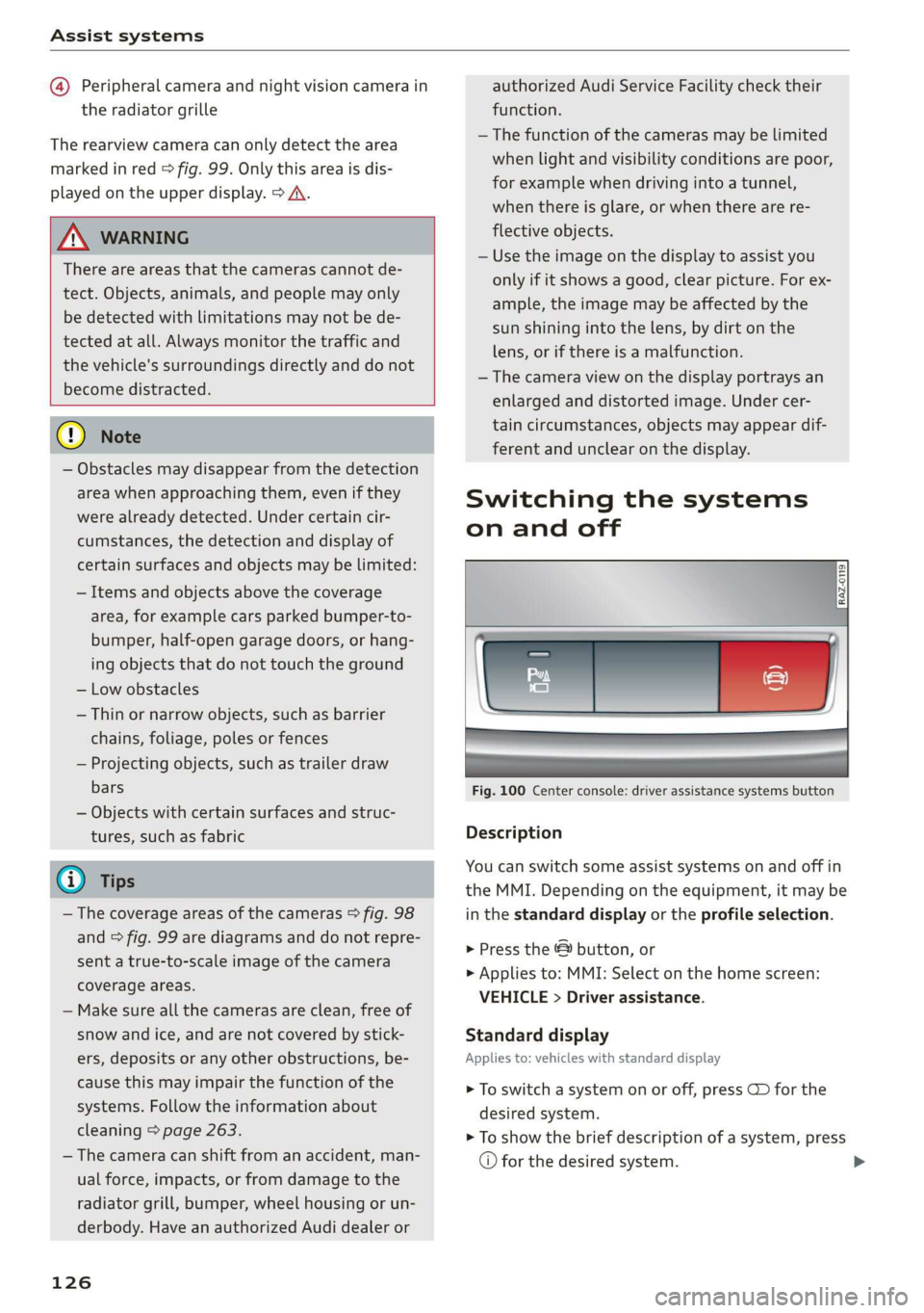
@ Peripheral camera and night vision camera in
the radiator grille
The rearview camera can only detect the area
marked in red > fig. 99. Only this area is dis-
played on the upper display. > A\.
Z\ WARNING
There are areas that the cameras cannot de-
tect. Objects, animals, and people may only
be detected with limitations may not be de-
tected at all. Always monitor the traffic and
the vehicle's surroundings directly and do not
become distracted.
® Note
— Obstacles may disappear from the detection
area when approaching them, even if they
were already detected. Under certain cir-
cumstances, the detection and display of
certain surfaces and objects may be limited:
— Items and objects above the coverage
area, for example cars parked bumper-to-
bumper, half-open garage doors, or hang-
ing objects that do not touch the ground
— Low obstacles
—Thin or narrow objects, such as barrier
chains, foliage, poles or fences
— Projecting objects, such as trailer draw
bars
— Objects with certain surfaces and struc-
tures, such as fabric
@® Tips
— The coverage areas of the cameras > fig. 98
and > fig. 99 are diagrams and do not repre-
sent a true-to-scale image of the camera
coverage areas.
— Make sure all the cameras are clean, free of
snow and ice, and are not covered by stick-
ers, deposits or any other obstructions, be-
cause this may impair the function of the
systems. Follow the information about
cleaning > page 263.
— The camera can shift from an accident, man-
ual force, impacts, or from damage to the
radiator grill, bumper, wheel housing or un-
derbody. Have an authorized Audi dealer or
126
authorized Audi Service Facility check their
function.
—The function of the cameras may be limited
when light and visibility conditions are poor,
for example when driving into a tunnel,
when there is glare, or when there are re-
flective objects.
— Use the image on the display to assist you
only if it shows a good, clear picture. For ex-
ample, the image may be affected by the
sun shining into the lens, by dirt on the
lens, or if there is a malfunction.
— The camera view on the display portrays an
enlarged and distorted image. Under cer-
tain circumstances, objects may appear dif-
ferent and unclear on the display.
Switching the systems
on and off
Fig. 100 Center console: driver assistance systems button
Description
You can switch some assist systems on and off in
the MMI. Depending on the equipment, it may be
in the standard display or the profile selection.
> Press the & button, or
> Applies to: MMI: Select on the home screen:
VEHICLE > Driver assistance.
Standard display
Applies to: vehicles with standard display
> To switch a system on or off, press CD for the
desired system.
> To show the brief description of a system, press
© for the desired system.
Page 129 of 310
4KE012721BB
Assist systems
Profile selection
Applies to: vehicles with profile selection
> To select a profile, press the profile name on
the upper display or press the & button repeat-
edly until the profile is active.
> To list systems included in a profile, select E]
on the upper display.
> To show the brief description of a system, se-
lect @ for the desired system.
> To switch individual systems on and off in the
Individual profile, select and C for the de-
sired systems.
The following profiles can be selected:
— Maximum - All available systems are switched
on in this profile.
— Individual - You can switch the systems on and
off individually in this profile.
— Basic or All off - Only the basic systems are
switched on in this profile. If no basic system is
available, the profile is All off.
Z\ WARNING
Follow the safety precautions and note the
limits of the assist systems, sensors, and
cameras > page 123.
@) Tips
Specific settings are stored automatically in
the active personal profile.
127
Page 130 of 310
Driving information
Driving information
Speed warning system
Applies to: vehicles with speed warning system
The speed warning system helps the driver to
stay below a specified maximum speed. A warn-
ing threshold can be set in the MMI for this pur-
pose.
Once the speed slightly exceeds the stored
threshold, the speed warning system will alert
the driver with an indicator in the instrument
cluster and a warning tone. Once the speed drops
below the stored maximum speed, the indicator
will turn off.
Setting a threshold is recommended if you would
like to be reminded when you reach a certain
maximum speed. Situations where you may want
to do so include driving in a country with a gener-
al speed limit or if there is a specified maximum
speed for winter tires.
@ Tips
Regardless of the speed warning system, you
should always monitor your speed using the
speedometer and make sure you are following
the legal speed limit.
Setting the warning threshold
Applies to: vehicles with speed warning system
> Applies to: MMI: Select on the home screen:
VEHICLE > Driver assistance > (<2) > Speed
warning.
@) Tips
Specific settings are stored automatically in
the active personal profile.
Py E NY
Applies to: vehicles with speed warning system
A display appears in the instrument cluster if the
stored speed is exceeded
by Manually set XX speed limit warning
threshold exceeded
128
Camera-based traffic
sign recognition
Applies to: vehicles with camera-based traffic sign recognition
Fig. 101 Instrument cluster: traffic sign recognition (dia-
gram)
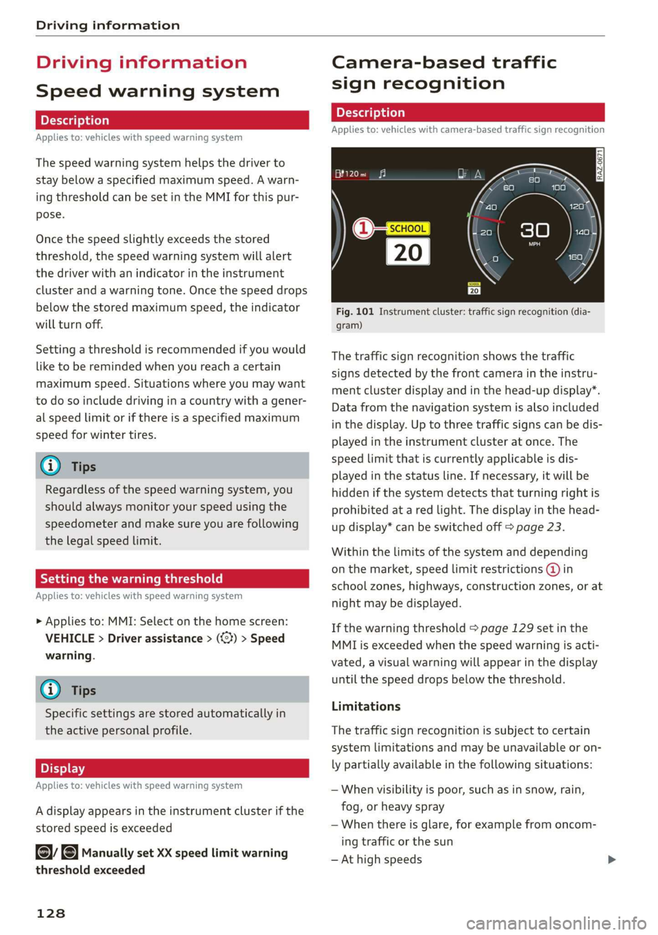
The traffic sign recognition shows the traffic
signs detected by the front camera in the instru-
ment cluster display and in the head-up display”.
Data from the navigation system is also included
in the display. Up to three traffic signs can be dis-
played in the instrument cluster at once. The
speed limit that is currently applicable is dis-
played in the status line. If necessary, it will be
hidden if the system detects that turning right is
prohibited at a red light. The display in the head-
up display* can be switched off > page 23.
Within the limits of the system and depending
on the market, speed limit restrictions @ in
school zones, highways, construction zones, or at
night may be displayed.
If the warning threshold > page 129 set in the
MMI is exceeded when the speed warning is acti-
vated, a visual warning will appear in the display
until the speed drops below the threshold.
Limitations
The traffic sign recognition is subject to certain
system limitations and may be unavailable or on-
ly partially available in the following situations:
— When visibility is poor, such as in snow, rain,
fog, or heavy spray
— When there is glare, for example from oncom-
ing traffic or the sun
— At high speeds