AUDI E-TRON 2019 Owners Manual
Manufacturer: AUDI, Model Year: 2019, Model line: E-TRON, Model: AUDI E-TRON 2019Pages: 310, PDF Size: 81.91 MB
Page 111 of 310
4KE012721BB
High-voltage system
—If the battery has been charged to the desired
level, the charging unit cover will automatically
relock. Otherwise, the cover must be manually
locked. To do this, press the center of the but-
ton @,.
— Disconnect the charging cable from the power
supply if necessary or return it securely to the
charging station.
— Install the protective caps on the charging ca-
ble again.
— If you are transporting the charging cable in
the vehicle, store it securely > page 113.
If the charging connector cannot be removed,
you must unlock it manually > page 111.
ing, drive immediately to an authorized Audi
dealer or authorized Audi Service Facility
and have the malfunction corrected to re-
duce the risk of injury.
ZA WARNING
— When closing the cover on the charging
unit, make sure the area where the cover is
closing is clear to reduce the risk of injury.
— Do not disconnect the charging cable from
the socket or the vehicle charging port while
the vehicle is charging. End the charging
process before removing the charging cable
from the socket in order to reduce the risk of
damaging the connector contacts from
sparks.
— Never drive with the charging unit open. If
the cover on the charging unit is open, it
could hit other road users and potentially
cause injury.
— If a charging unit is damaged, the vehicle
must not be charged at the damaged charg-
ing port or at the charging port on the other
side* to reduce the risk of injury.
— If the charging unit is damaged or the
charging unit cover cannot close or is miss-
@) Note
— If you drive with an open charging unit, both
the cover and the electronics installed be-
hind it could be damaged. Check before ev-
ery drive after charging if the cover is
locked.
— Applies to: vehicles with charging ports on
the driver and front passenger’s side: Never
attempt to charge the vehicle using both
charging ports at the same time, because
this could damage the charging infrastruc-
ture.
(i) Tips
— Applies to: MMI: in addition to other set-
tings, you can also select if the charging
connector should be released automatically
after the immediate charging process is
complete. To do this, select on the home
screen: VEHICLE > Charging & Efficiency >
Charging > <3 > DC connector: unlock after
charging ends.
— The parking brake may make noises when
connecting the charging connector.
— Remove ice and snow in the charging unit
using a hand brush and solvent-free deicing
spray.
— The vehicle radio and TV systems may have
limited reception when charging the vehicle.
Charging display
The charging display is an LED light on the charg-
ing unit and shows the charging status. A label
on the charging unit @) > page 108, fig. 90 in-
forms you about the various displays. The key for
the LED light is explained in the following table.
LED on the charging unit Meaning
Vehicle charging system is in sleep mode. A timer may be active,
Off but charging has not started yet.
Charging process is interrupted. >
109
Page 112 of 310
High-voltage system
LED on the charging unit Meaning
White Pulsing
Connection between the power source and the vehicle is being
established.
Green
Pulsing The high-voltage battery is charging.
Flashing A timer is active, but charging has not started yet.
On High-voltage battery charging process is completed.
Yellow
On
No power supply was recognized even though the charging cable
is plugged in. Have the power supply or power supply system in-
spected. When using the Audi charging system, check the status
displays on the unit > table on page 115. See an authorized Au-
di dealer or authorized Audi Service Facility for assistance if nec-
essary.
Flashing
The vehicle is not secured from rolling away. Check if “P” is en-
gaged and the parking brake is set. If the LED continues to
flash, see an authorized Audi dealer or authorized Audi Service
Facility for assistance.
Red
On
The charging connector may not be able to lock correctly in the
vehicle charging port. Check if the charging connector is insert-
ed correctly. Remove the charging connector and plug it in the
charging port again, or use a different charging station. If the
LED stays turned on, there is a malfunction either in the vehicle
charging system or at the power source. See an authorized Audi
dealer or authorized Audi Service Facility for assistance if neces-
sary.
Both charging unit covers are open. Try to close one of the cov-
ers by hand. If the LED stays turned on, the high-voltage battery
may not be charging. See an authorized Audi dealer or author-
ized Audi Service Facility for assistance.
The outside temperature is too low or too high.
@ Tips
The operation status indicated by the LED on
> Applies to: MMI: Select on the home screen:
VEHICLE > Charging & Efficiency > Charging.
>» When the timer is displayed, swipe your finger
the charging unit are is displayed in the in-
strument cluster gy.
Setting the charging target
You can set the charging target, meaning you can
set the maximum charge level to which the high-
voltage battery should be charged. The charging
target can be set between 50% and 100%. For
daily usage, Audi recommends setting the charg-
ing target at 80%. This can extend the service life
of the high-voltage battery. Before long trips, Au-
di recommends setting the charging target at
100% for the highest possible range.
110
on the display toward the right.
> Press on the right section of the battery charge
level display.
> Set the desired charging target.
G) Tips
If you set the charging target lower than the
current battery charge level while charging,
then the charging process will be canceled. If
you set the charging target above the current
battery charge level again, then the charging
process will resume. This does not apply if you
are charging at a charging station, where you
have authenticated yourself manually. If this >
Page 113 of 310
4KE012721BB
High-voltage system
is the case, authenticate yourself again at the
charging station.
Sytem nas
By setting a timer, you determine when your vehi-
cle should reach the desired charging target.
When the timer is activated, it will be run regu-
larly at the set time. In addition to the charging
target, you can also specify if your vehicle should
be heated or cooled to the temperature set in the
climate control system. You can turn on multiple
timers at the same time. The active timer is indi-
cated by the respective number in © in the upper
section of the display.
> Applies to: MMI: Select on the home screen:
VEHICLE > Charging & Efficiency > Charging.
> When the charging target is displayed, swipe
your finger on the display toward the left.
Multiple timers are displayed that you can set
separately.
> To set a timer, select > in the line for the de-
sired timer.
> Select one ore more days of the week and select
Next.
> Set the desired departure time and select OK.
> To also activate the climate control with a tim-
er, select F.
> To turn ona timer, select CD.
> To activate the timer that is turned on, select
©. A colored bar will turn on in the button.
If the set departure time for the timer is too
soon, the desired charging target may not be
reached.
G) Tips
It is not possible to charge using the timer at
some charging stations.
Advanced charging settings
With the advanced charging settings, you can de-
fine
addresses at which certain charging settings
should apply (for example, charging target, mini-
mum charge). If your vehicle is in the vicinity of
the address, the charging settings will be auto-
matically applied.
> Applies to: MMI: Select on the home screen:
VEHICLE > Charging & Efficiency > Charging >
<2} > Advanced charging settings.
> To define new settings for a certain address, se-
lect +. Follow the instructions in the display.
> To edit existing settings for a certain address,
press the respective button.
> To delete existing settings for a certain ad-
dress, select Z.
Emergency release
You can release the charging unit cover or the
charging connector manually.
Fig. 91 Motor compartment: emergency release
Charging unit cover emergency release
> Open the hood > page 236.
> Open the cover in the motor compartment on
the side of the applicable charging port.
> Loosen the red loop (@ from the retainer and
then pull on the loop carefully >@.
> If necessary, open the charging unit cover by
hand.
Manually releasing the charging connector
If you are not able to pull the charging connector
out of the vehicle charging port, there may bea
malfunction. You must use the emergency re-
lease to release the vehicle charging connector.
Requirement: the “P” gear must be selected, the
vehicle must be unlocked, and the charging proc-
ess must be complete or must have been can-
celed.
> End the charging process > page 108, Cancel-
ing or completing charging.
> Open the hood & page 236.
111
Page 114 of 310
High-voltage system
> Open the cover in the motor compartment on
the side of the applicable charging port.
> Loosen the yellow loop (2) from the retainer
and then pull on the loop carefully >@).
> Remove the charging connector.
> Drive to an authorized Audi dealer or author-
ized Audi Service Facility immediately to have
the malfunction corrected.
If the charging connector still cannot be removed
after using the emergency release, see an author-
ized Audi dealer or authorized Audi Service Facili-
ty for assistance.
After releasing manually, secure the loop(s) on
the retainer and close the cover in the motor
compartment.
() Note
Only pull on the loop until you feel resistance.
You
will not hear it release. If you continue to
pull, you could damage the emergency re-
lease mechanism.
Messages
If the or =] indicator light turns on, then the
range is low or very low. Charge the high-voltage
battery.
Esq Warning! Please check the charging unit
cover. See owner's manual
This message appears if the charging unit cover is
opened while driving. Stop the vehicle as soon as.
possible and try to close the cover using the but-
ton @ © page 108, fig. 89 or by hand. If the cov-
er cannot close and/or the message continues to
appear, drive to an authorized Audi dealer or au-
thorized Audi Service Facility immediately and
have the malfunction corrected > A\ in Charging
on page 109; >@ in Charging on page 109.
B AC charging system: malfunction! Please
contact Service
B DC charging system: malfunction! Please
contact Service
This message appears if there is a malfunction in
the charging system. Drive to an authorized Audi
112
dealer or authorized Audi Service Facility immedi-
ately.
Incompatible charging system. Please check
charging system
This message appears when the charging system
is incompatible. Only charge using the Audi
charging system that is designed for your vehicle.
EB charging system: malfunction
This message appears if there is a malfunction in
the vehicle charging infrastructure or the charg-
ing station. Use a different charging station. If
this message does not turn off, contact an au-
thorized Audi dealer or authorized Audi Service
Facility.
Charging equipment
Introduction
Depending on the vehicle equipment, the Audi e-
tron compact charging system may be available.
Using the charging equipment
Pay attention to the following information for
safe handling of the charging equipment:
— Secure the charging equipment against any
strain, such as being run over, falling, pulling,
bending, and crushing.
— Do not submerge the charging equipment in
water and do not cover it with snow or ice.
— Only pull at the plugs when removing the
charging cable from the vehicle and from the
power supply.
— Put the cap on after using the charging cable.
— Only operate the Audi charging system ina
power supply system with a frequency of
50 Hz/60 Hz.
— Only operate or store the Audi charging system
at a humidity level between 5% and 95% (no
condensation).
— The Audi charging system is protected against
dust and splashing water (IP55 (USA: Enclosure
3).
Depending on the country, different warnings
may be on the charging equipment.
Page 115 of 310
4KE012721BB
High-voltage system
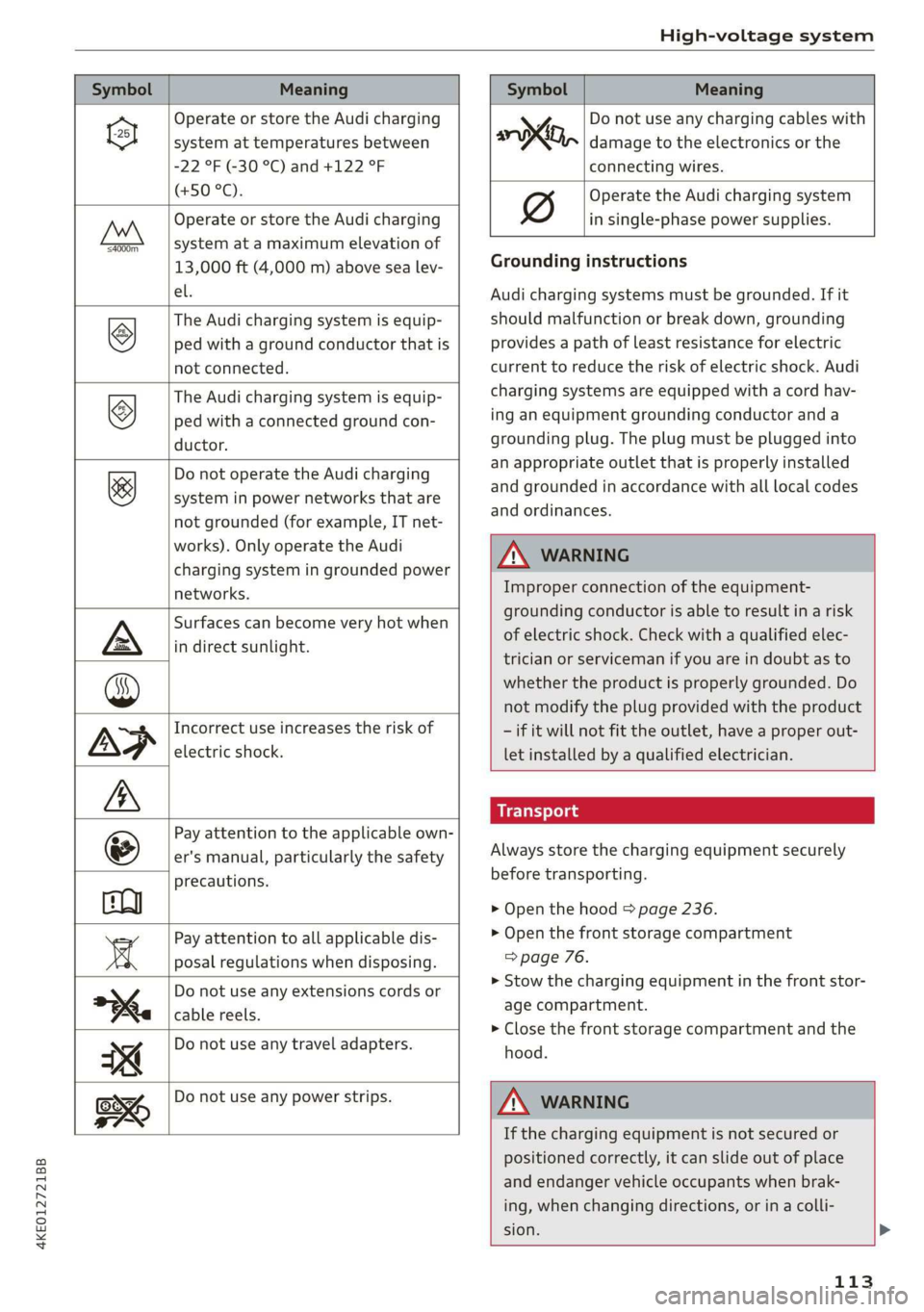
Symbol Meaning Meaning
Operate or store the Audi charging
system at temperatures between
-22 °F (-30 °C) and +122 °F
(+50 °C).
Operate or store the Audi charging
system at a maximum elevation of
4000m_
13,000 ft (4,000 m) above sea lev-
el.
The Audi charging system is equip-
ped with a ground conductor that is
not connected.
©
The Audi charging system is equip-
ped with a connected ground con-
ductor.
&
Do not operate the Audi charging
system in power networks that are
not grounded (for example, IT net-
works). Only operate the Audi
charging system in grounded power
networks.
Surfaces can become very hot when
in direct sunlight.
Incorrect use increases the risk of
electric shock.
Pay attention to the applicable own-
er's manual, particularly the safety
precautions.
Pay attention to all applicable dis-
posal regulations when disposing.
Do not use any extensions cords or
cable reels.
Do not use any travel adapters.
y Do not use any charging cables with
oo, damage to the electronics or the
connecting wires.
Operate the Audi charging system
in single-phase power supplies.
Grounding instructions
Audi charging systems must be grounded. If it
should malfunction or break down, grounding
provides a path of least resistance for electric
current to reduce the risk of electric shock. Audi
charging systems are equipped with a cord hav-
ing an equipment grounding conductor and a
grounding plug. The plug must be plugged into
an appropriate outlet that is properly installed
and grounded in accordance with all local codes
and ordinances.
Z\ WARNING
Improper connection of the equipment-
grounding conductor is able to result in a risk
of electric shock. Check with a qualified elec-
trician or serviceman if you are in doubt as to
whether the product is properly grounded. Do
not modify the plug provided with the product
- if it will not fit the outlet, have a proper out-
let installed by a qualified electrician.
Always store the charging equipment securely
before transporting.
> Open the hood > page 236.
> Open the front storage compartment
=> page 76.
>» Stow the charging equipment in the front stor-
age compartment.
> Close the front storage compartment and the
hood.
Do not use any power strips.
Z\ WARNING
If the charging equipment is not secured or
positioned correctly, it can slide out of place
and endanger vehicle occupants when brak-
ing, when changing directions, or in a colli-
sion. >
113
Page 116 of 310
High-voltage system
— Only transport the charging equipment in
the front storage compartment and never
unsecured or in the passenger compart-
ment.
C@) Note
Always lift or carry the Audi charging system
as one unit and never by the cables.
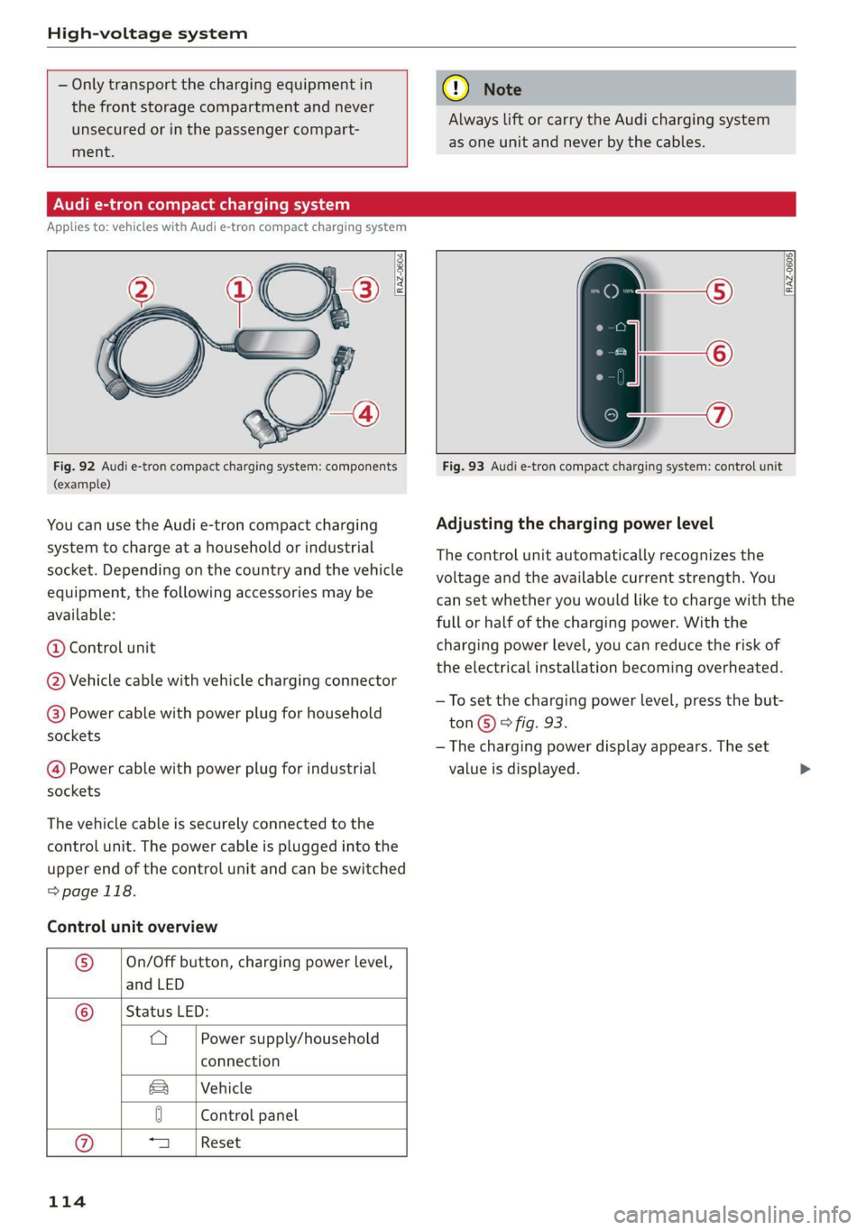
Audi e-tron compact charging system
Applies to: vehicles with Audi e-tron compact charging system
o~ |
[RAZ-0605|
Fig. 92 Audi e-tron compact charging system: components
(example)
You can use the Audi e-tron compact charging
system to charge at a household or industrial
socket. Depending on the country and the vehicle
equipment, the following accessories may be
available:
@ Control unit
@ Vehicle cable with vehicle charging connector
@® Power cable with power plug for household
sockets
@ Power cable with power plug for industrial
sockets
The vehicle cable is securely connected to the
control unit. The power cable is plugged into the
upper end of the control unit and can be switched
=>page 118.
Control unit overview
® On/Off button, charging power level,
and LED
© _ |Status LED:
a Power supply/household
connection
Vehicle
Sa
0 Control panel
a Reset
114
Fig. 93 Audi e-tron compact charging system: control unit
Adjusting the charging power level
The control unit automatically recognizes the
voltage and the available current strength. You
can set whether you would like to charge with the
full or half of the charging power. With the
charging power level, you can reduce the risk of
the electrical installation becoming overheated.
—To set the charging power level, press the but-
ton©) & fig. 93.
— The charging power display appears. The set
value is displayed.
Page 117 of 310
4KE012721BB
High-voltage system
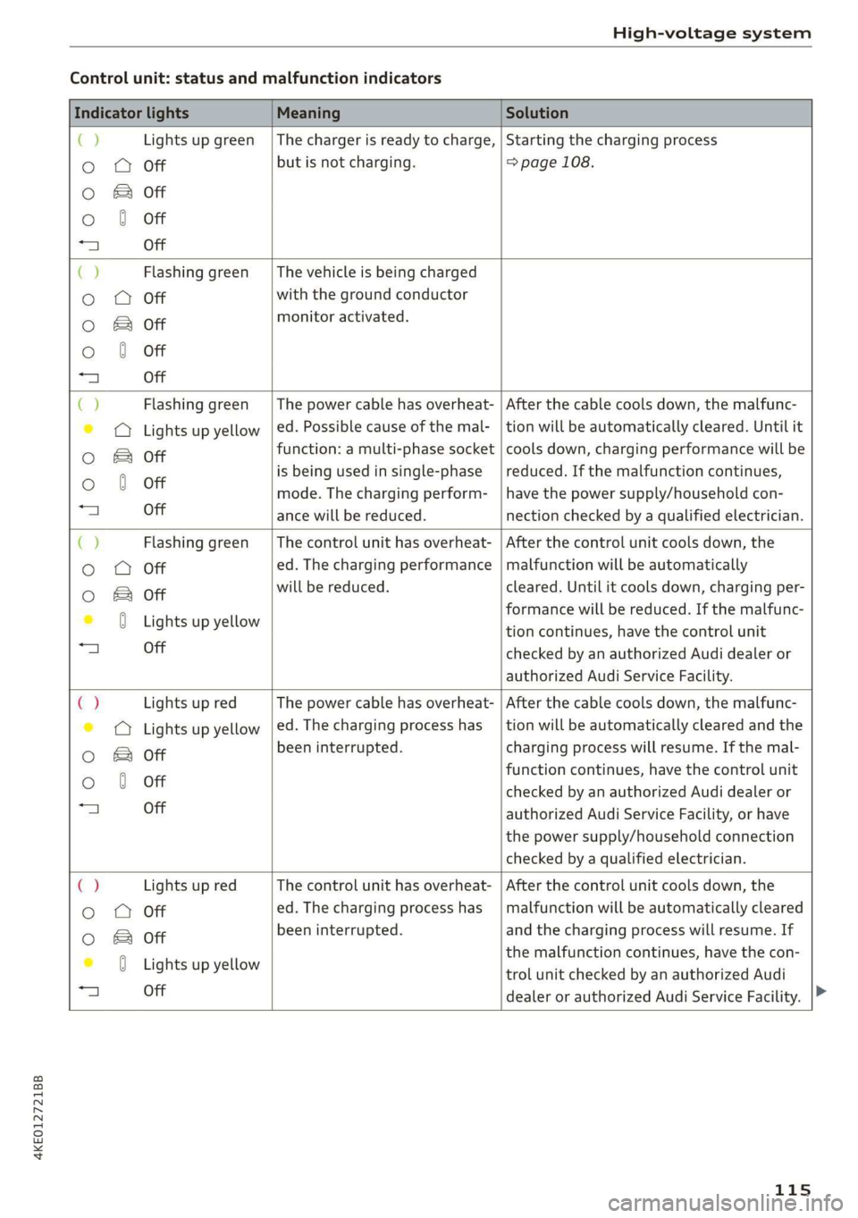
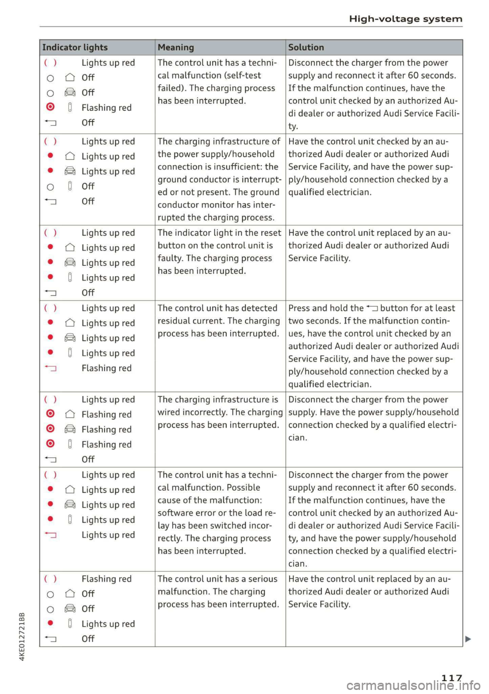
Control unit: status and malfunction indicators
Indicator lights Meaning Solution
() Lights up green |The charger is ready to charge, | Starting the charging process
o OQ Off but is not charging. => page 108.
O & Off
o 0 Off
=) Off
CJ Flashing green _| The vehicle is being charged
o Q Off with the ground conductor
oO B of monitor activated.
o 0 Off
a) Off
() Flashing green _| The power cable has overheat- | After the cable cools down, the malfunc-
© © Lights up yellow | ed. Possible cause of the mal- | tion will be automatically cleared. Until it
Oo & off function: a multi-phase socket | cools down, charging performance will be
Oo 0 Off is being used in single-phase | reduced. If the malfunction continues,
mode. The charging perform- | have the power supply/household con-
“4 Off ance will be reduced. nection checked by a qualified electrician.
() Flashing green | The control unit has overheat- | After the control unit cools down, the
o O Off ed. The charging performance | malfunction will be automatically
oO B of will be reduced. cleared. Until it cools down, charging per-
© 0 Lights up yellow formance will be reduced. If the malfunc-
tion continues, have the control unit
“a Off checked by an authorized Audi dealer or
authorized Audi Service Facility.
() Lights up red The power cable has overheat- | After the cable cools down, the malfunc-
© © Lights up yellow |ed. The charging process has __| tion will be automatically cleared and the
oO B of been interrupted. charging process will resume. If the mal-
function continues, have the control unit
o 0 off checked by an authorized Audi dealer or
“a Off authorized Audi Service Facility, or have
the power supply/household connection
checked by a qualified electrician.
C2 Lights up red The control unit has overheat- | After the control unit cools down, the
Oo O Off ed. The charging process has__| malfunction will be automatically cleared
oO B off been interrupted. and the charging process will resume. If
iG Ligteewp yelbaw the malfunction continues, have the con-
trol unit checked by an authorized Audi
1 Off
dealer or authorized Audi Service Facility.
115
Page 118 of 310
High-voltage system
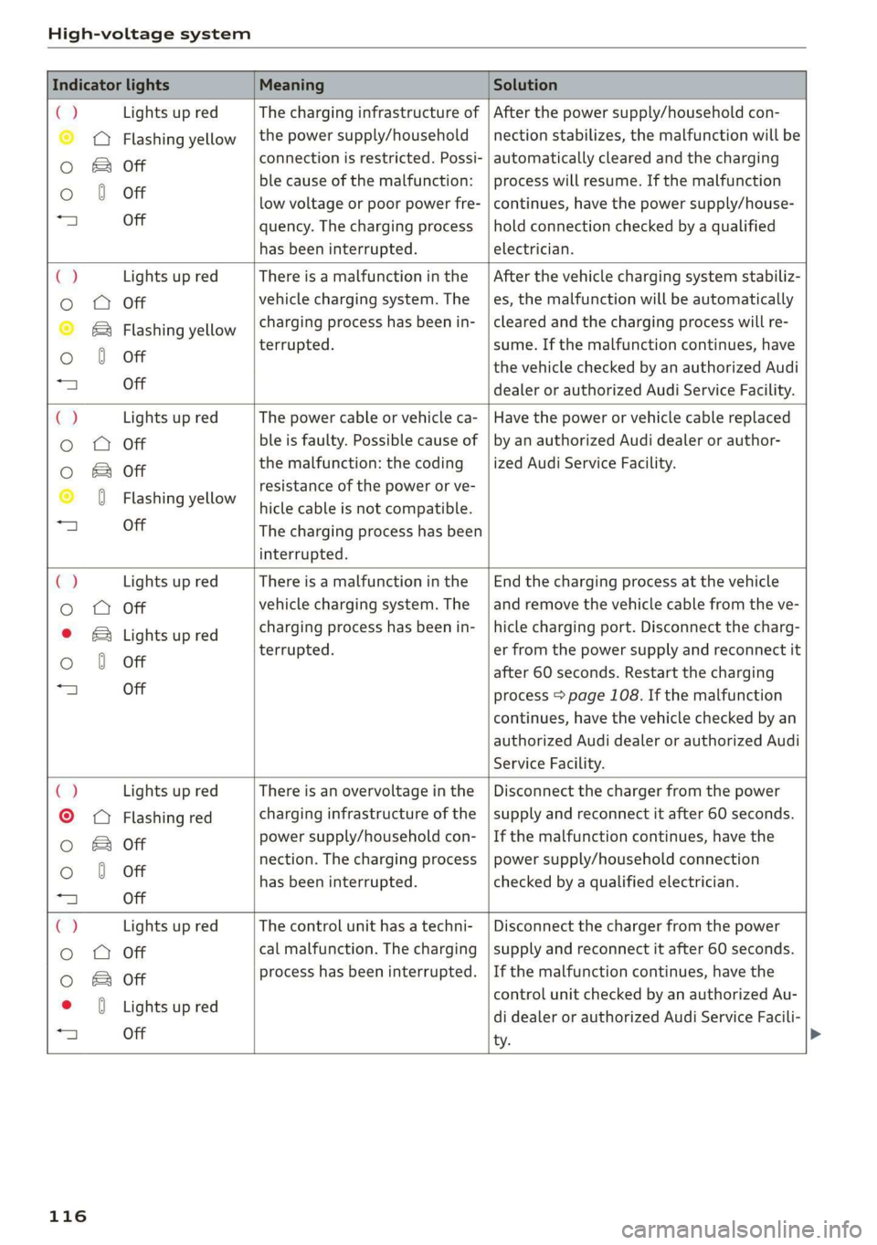
Indicator lights Meaning Solution
ia Lights up red The charging infrastructure of | After the power supply/household con-
© © Flashing yellow |the power supply/household | nection stabilizes, the malfunction will be
Oo B of connection is restricted. Possi- | automatically cleared and the charging
o 8 of ble cause of the malfunction: | process will resume. If the malfunction
low voltage or poor power fre- | continues, have the power supply/house-
“4 Off quency. The charging process | hold connection checked by a qualified
has been interrupted. electrician.
4 Lights up red There is a malfunction inthe | After the vehicle charging system stabiliz-
o O Off vehicle charging system. The | es, the malfunction will be automatically
© B® Flashing yellow charging process has been in- | cleared and the charging process will re-
oO 6 Off terrupted. sume. If the malfunction continues, have
the vehicle checked by an authorized Audi
“A Off dealer or authorized Audi Service Facility.
C2 Lights up red The power cable or vehicle ca- | Have the power or vehicle cable replaced
o OQ Off ble is faulty. Possible cause of | by an authorized Audi dealer or author-
oO B otf the malfunction: the coding _| ized Audi Service Facility.
© 0 Flashing yellow resistance of the power or ve-
hicle cable is not compatible.
a) Off The charging process has been
interrupted.
€) Lights up red There is a malfunction in the | End the charging process at the vehicle
o OQ Off vehicle charging system. The | and remove the vehicle cable from the ve-
© B Lights up red charging process has been in- | hicle charging port. Disconnect the charg-
Oo 0 Off terrupted. er from the power supply and reconnect it
after 60 seconds. Restart the charging
“a Off process > page 108. If the malfunction
continues, have the vehicle checked by an
authorized Audi dealer or authorized Audi
Service Facility.
() Lights up red There is an overvoltage inthe | Disconnect the charger from the power
©
© Flashing red charging infrastructure of the | supply and reconnect it after 60 seconds.
Oo B of power supply/household con- | If the malfunction continues, have the
Oo 0 Off nection. The charging process | power supply/household connection
has been interrupted. checked by a qualified electrician.
=| Off
Ca Lights up red The control unit has atechni- | Disconnect the charger from the power
Oo QO Off cal malfunction. The charging | supply and reconnect it after 60 seconds.
0 & of process has been interrupted. | If the malfunction continues, have the
* 0 vightsupred control unit checked by an authorized Au-
25 see di dealer or authorized Audi Service Facili-
ty.
116
Page 119 of 310
4KE012721BB
High-voltage system
Indicator lights Meaning Solution
() Lights up red The control unit has atechni- | Disconnect the charger from the power
o Q Off cal malfunction (self-test supply and reconnect it after 60 seconds.
oO B of failed). The charging process _ | If the malfunction continues, have the
© 0) Flashing red has been interrupted. control unit checked by an authorized Au-
di dealer or authorized Audi Service Facili-
a Off ty.
C) Lights up red The charging infrastructure of | Have the control unit checked by an au-
@ © Lights up red the power supply/household | thorized Audi dealer or authorized Audi
© ®& Lights up red connection is insufficient: the | Service Facility, and have the power sup-
ground conductor is interrupt- | ply/household connection checked by a
Oo 0 Off ed or not present. The ground | qualified electrician.
“al Off conductor monitor has inter-
rupted the charging process.
() Lights up red The indicator light in the reset | Have the control unit replaced by an au-
@ © Lights up red button on the control unit is | thorized Audi dealer or authorized Audi
© B Lights up red faulty. The charging process _| Service Facility.
. has been interrupted.
e@ J Lights up red
1 Off
() Lights up red The control unit has detected | Press and hold the *— button for at least
© © Lights up red residual current. The charging |two seconds. If the malfunction contin-
© & Lights up red process has been interrupted. | ues, have the control unit checked by an
© 0 Lights up red authorized Audi dealer or authorized Audi
Service Facility, and have the power sup-
“a Flashing red ply/household connection checked by a
qualified electrician.
c) Lights up red The charging infrastructure is | Disconnect the charger from the power
©
Q Flashing red wired incorrectly. The charging | supply. Have the power supply/household
© & Flashing red process has been interrupted. | connection checked by a qualified electri-
© ( Flashing red Sil
“a Off
() Lights up red The control unit has atechni- | Disconnect the charger from the power
@ © Lights up red cal malfunction. Possible supply and reconnect it after 60 seconds.
© B Lights up red cause of the malfunction: If the malfunction continues, have the
MD Lightsup red software error or the load re-__| control unit checked by an authorized Au-
lay has been switched incor- | di dealer or authorized Audi Service Facili-
| Lights up red rectly. The charging process __| ty, and have the power supply/household
has been interrupted. connection checked by a qualified electri-
cian.
() Flashing red The control unit has a serious | Have the control unit replaced by an au-
Oo QO Off malfunction. The charging thorized Audi dealer or authorized Audi
oO B of process has been interrupted. | Service Facility.
e (Lights up red
+ Off
117
Page 120 of 310
High-voltage system
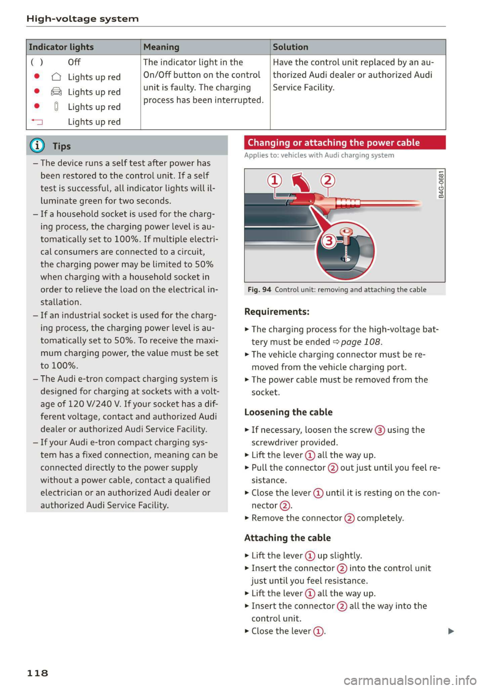
Indicator lights Meaning Solution
() Off The indicator light in the
© © Lights up red On/Off button on the control
© & Lights up red unit is faulty. The charging
. process has been interrupted.
e {Lights up red
aj Lights up red
Have the control unit replaced by an au-
thorized Audi dealer or authorized Audi
Service Facility.
@ Tips
— The device runs a self test after power has
been restored to the control unit. If a self
test is successful, all indicator lights will il-
luminate green for two seconds.
— If a household socket is used for the charg-
ing process, the charging power level is au-
tomatically set to 100%. If multiple electri-
cal consumers are connected to a circuit,
the charging power may be limited to 50%
when charging with a household socket in
order to relieve the load on the electrical in-
stallation.
— If an industrial socket is used for the charg-
ing process, the charging power level is au-
tomatically set to 50%. To receive the maxi-
mum charging power, the value must be set
to 100%.
— The Audi e-tron compact charging system is
designed for charging at sockets with a volt-
age of 120 V/240 V. If your socket has a dif-
ferent voltage, contact and authorized Audi
dealer or authorized Audi Service Facility.
— If your Audi e-tron compact charging sys-
tem has a fixed connection, meaning can be
connected directly to the power supply
without a power cable, contact a qualified
electrician or an authorized Audi dealer or
authorized Audi Service Facility.
118
Changing or attaching the power cable
Applies to: vehicles with Audi charging system
NL ?
B4G-0681
Fig. 94 Control unit: removing and attaching the cable
Requirements:
> The charging process for the high-voltage bat-
tery must be ended > page 108.
> The vehicle charging connector must be re-
moved from the vehicle charging port.
> The power cable must be removed from the
socket.
Loosening the cable
> If necessary, loosen the screw (3) using the
screwdriver provided.
> Lift the lever @ all the way up.
> Pull the connector @) out just until you feel re-
sistance.
> Close the lever @) until it is resting on the con-
nector (2).
» Remove the connector (2) completely.
Attaching the cable
> Lift the lever @ up slightly.
> Insert the connector (2) into the control unit
just until you feel resistance.
> Lift the lever @ all the way up.
> Insert the connector (2) all the way into the
control unit.
> Close the lever @).