instrument cluster AUDI E-TRON 2019 User Guide
[x] Cancel search | Manufacturer: AUDI, Model Year: 2019, Model line: E-TRON, Model: AUDI E-TRON 2019Pages: 310, PDF Size: 81.91 MB
Page 46 of 310
Lights and Vision
Lights and Vision
Exterior lighting
Sitar MeL Lats eal
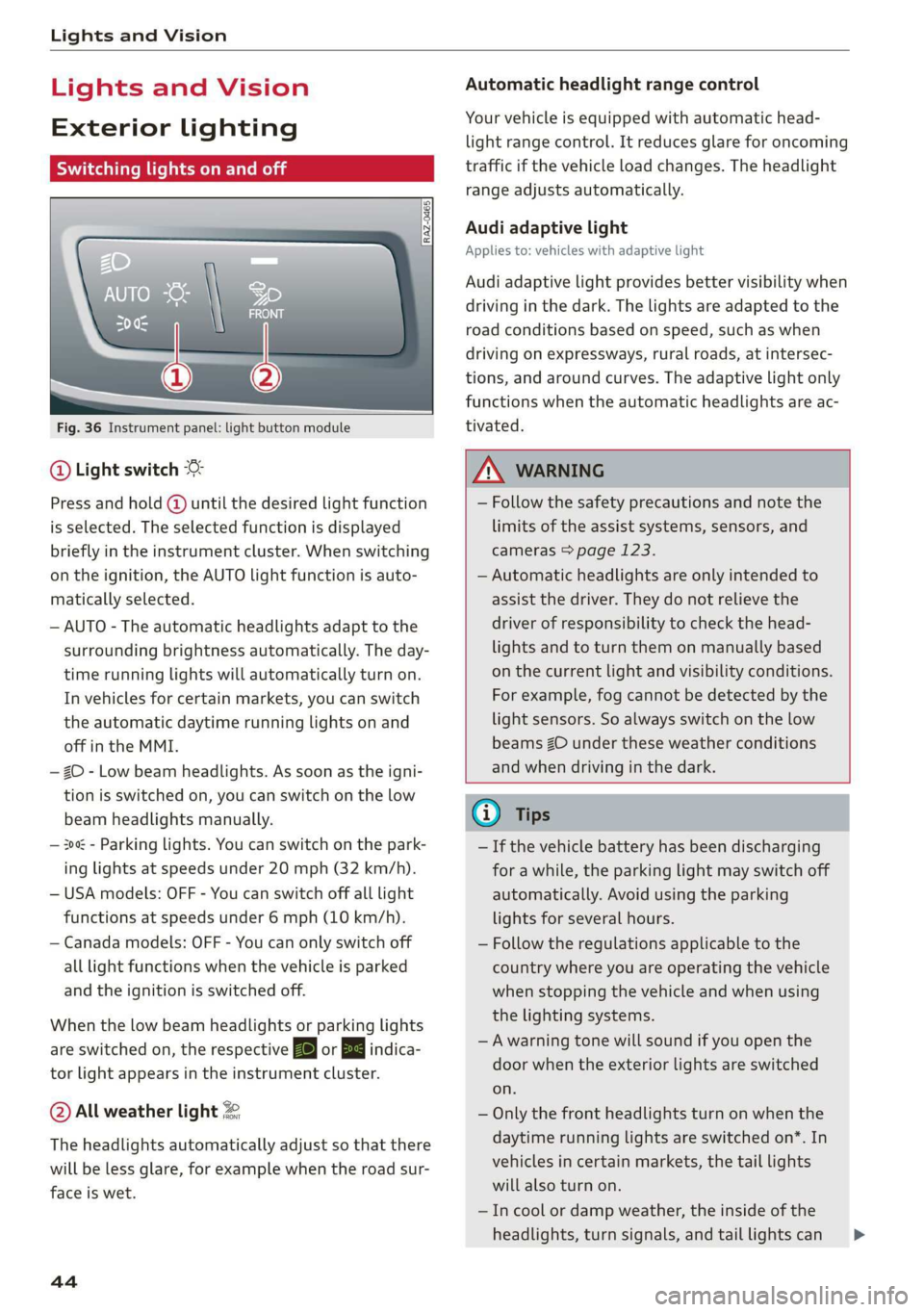
Fig. 36 Instrument panel: light button module
@ Light switch &
Press and hold @ until the desired light function
is selected. The selected function is displayed
briefly in the instrument cluster. When switching
on the ignition, the AUTO light function is auto-
matically selected.
— AUTO - The automatic headlights adapt to the
surrounding brightness automatically. The day-
time running lights will automatically turn on.
In vehicles for certain markets, you can switch
the automatic daytime running lights on and
off in the MMI.
— 20 - Low beam headlights. As soon as the igni-
tion is switched on, you can switch on the low
beam headlights manually.
— 30a - Parking lights. You can switch on the park-
ing lights at speeds under 20 mph (32 km/h).
— USA models: OFF - You can switch off all light
functions at speeds under 6 mph (10 km/h).
— Canada models: OFF - You can only switch off
all light functions when the vehicle is parked
and the ignition is switched off.
When the low beam headlights or parking lights
are switched on, the respective Ba or Ea indica-
tor light appears in the instrument cluster.
@ All weather light 2
The headlights automatically adjust so that there
will be less glare, for example when the road sur-
face is wet.
44
Automatic headlight range control
Your vehicle is equipped with automatic head-
light range control. It reduces glare for oncoming
traffic if the vehicle load changes. The headlight
range adjusts automatically.
Audi adaptive light
Applies to: vehicles with adaptive light
Audi adaptive light provides better visibility when
driving in the dark. The lights are adapted to the
road conditions based on speed, such as when
driving on expressways, rural roads, at intersec-
tions, and around curves. The adaptive light only
functions when the automatic headlights are ac-
tivated.
A WARNING
— Follow the safety precautions and note the
limits of the assist systems, sensors, and
cameras > page 123.
— Automatic headlights are only intended to
assist the driver. They do not relieve the
driver of responsibility to check the head-
lights and to turn them on manually based
on the current light and visibility conditions.
For example, fog cannot be detected by the
light sensors. So always switch on the low
beams ZO under these weather conditions
and when driving in the dark.
@ Tips
— If the vehicle battery has been discharging
for a while, the parking light may switch off
automatically. Avoid using the parking
lights for several hours.
— Follow the regulations applicable to the
country where you are operating the vehicle
when stopping the vehicle and when using
the lighting systems.
—Awarning tone will sound if you open the
door when the exterior lights are switched
on.
— Only the front headlights turn on when the
daytime running lights are switched on*. In
vehicles in certain markets, the tail lights
will also turn on.
—Incool or damp weather, the inside of the
headlights, turn signals, and tail lights can >
Page 47 of 310
4KE012721BB
Lights and Vision
fog over due to the temperature difference
between the inside and outside. They will
clear shortly after switching them on. This
does not affect the service life of the light-
ing.
— When the parking lights are switched on
and the ignition is switched off, the 200: sym-
bol appears in the light switch module.
Turn signal and high beam lever
©
gS
©
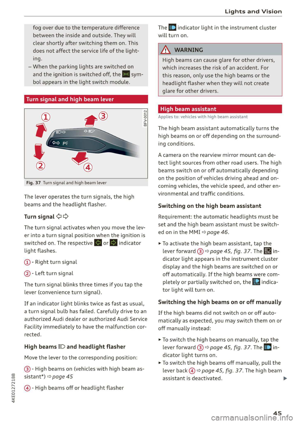
Fig. 37 Turn signal and high beam lever
The lever operates the turn signals, the high
beams and the headlight flasher.
Turn signal @>
The turn signal activates when you move the lev-
er into a turn signal position when the ignition is
switched on. The respective a or B indicator
light flashes.
@- Right turn signal
@- Left turn signal
The turn signal blinks three times if you tap the
lever (convenience turn signal).
If an indicator light blinks twice as fast as usual,
a turn signal bulb has failed. Carefully drive to an
authorized Audi dealer or authorized Audi Service
Facility immediately to have the malfunction cor-
rected.
High beams ZO and headlight flasher
Move the lever to the corresponding position:
@- High beams on (vehicles with high beam as-
sistant*) > page 45
@- High beams off or headlight flasher The
0) indicator light in the instrument cluster
will turn on.
ZA WARNING
High beams can cause glare for other drivers,
which increases the risk of an accident. For
this reason, only use the high beams or the
headlight flasher when they will not create
glare for other drivers.
teh old
Applies to: vehicles with high beam assistant
The high beam assistant automatically turns the
high beams on or off depending on the surround-
ing conditions.
A camera on the rearview mirror mount can de-
tect light sources from other road users. The high
beams switch on or off automatically depending
on the position of vehicles driving ahead and on-
coming vehicles, the vehicle speed, and other en-
vironmental and traffic conditions.
Switching on the high beam assistant
Requirement: the automatic headlights must be
set and the high beam assistant must be switch-
ed on in the MMI = page 46.
> To activate the high beam assistant, tap the
lever forward @) > page 45, fig. 37. The FM in-
dicator light appears in the instrument cluster
display and the high beams are switched on or
off automatically. If the high beams were com-
pletely or partially switched on, the Ea indica-
tor light will turn on.
Switching the high beams on or off manually
If the high beams did not switch on or off auto-
matically as expected, you may switch them on or
off manually instead:
> To switch the high beams on manually, tap the
lever
forward @) > page 45, fig. 37. The =| in-
dicator light turns on.
> To switch the high beams off manually, pull the
lever
back @) > page 45, fig. 37. The high beam
assistant is deactivated.
4s
Page 58 of 310
Sitting correctly and safely
Front seats
(erreur laced)
Make sure that:
— You can press the pedals down completely
when your legs are slightly bent
— The distance between your upper body and the
steering wheel or instrument panel is at least
10 in (25 cm)
— The distance between your knees and the in-
strument panel is at least 4 in (10 cm)
— Your thighs are lightly supported by the front
surface of the seat
— The backrest is in an upright position and your
back is resting against it
— You have a sufficient view of the area around
the vehicle
— You have a clear view of the instrument cluster,
indicator lights, and the head-up display*
Seat settings menu: quick access
Applies to: vehicles with seat settings in the MMI
If you press on the image of the driver's or front
passenger's seat in the climate control system
menu > page 81, fig. 83 @, you will go directly
to the seat settings for that seat.
Z\ WARNING
— If you are too close to the steering wheel or
instrument panel, the airbag system cannot
provide the optimal protection, which in-
creases the risk of injury and death.
—To reduce the risk of injury in the event of
sudden braking maneuvers or accidents,
never drive with the backrest reclined very
far. The airbag system and seat belts can on-
ly provide optimal protection when the back-
rest is in an upright position and the driver
is wearing the seat belt correctly. If the
backrest is angled back too far, the safety
belt can shift to soft areas of the body, such
as the stomach, which increases the risk of
injury.
—To reduce the risk of an accident, only adjust
the seats when the vehicle is stationary.
— Be careful when adjusting the seat. Lack of
control or attention when adjusting can re-
56
sult in injuries due to pinching to vehicle oc-
cupants both in the front seats and rear
seats.
— Never place objects in the driver's footwell.
Objects could shift and enter the area
around the pedals, which could prevent you
from using them. You would then be unable
to use the pedals if sudden driving or brak-
ing maneuvers were needed, which increas-
es the risk of an accident.
— Make sure that the floor mats are always se-
curely attached.
—To reduce the risk of an accident, never place
additional floor mats or other floor covers
over the installed floor mats, because this
reduces the pedal's range of motion and can
impair pedal operation.
—To reduce the risk of injury, never place your
feet on the instrument panel, out of the
window, or on the seat surfaces. This also
applies to passengers in the rear seats.
@) Note
To reduce the risk of damage, be very careful
when adjusting the seat to make sure the
head restraints do not come into contact with
the headliner or the sunroof*.
@ Tips
At the same time, only move the respective
seat using the controls.
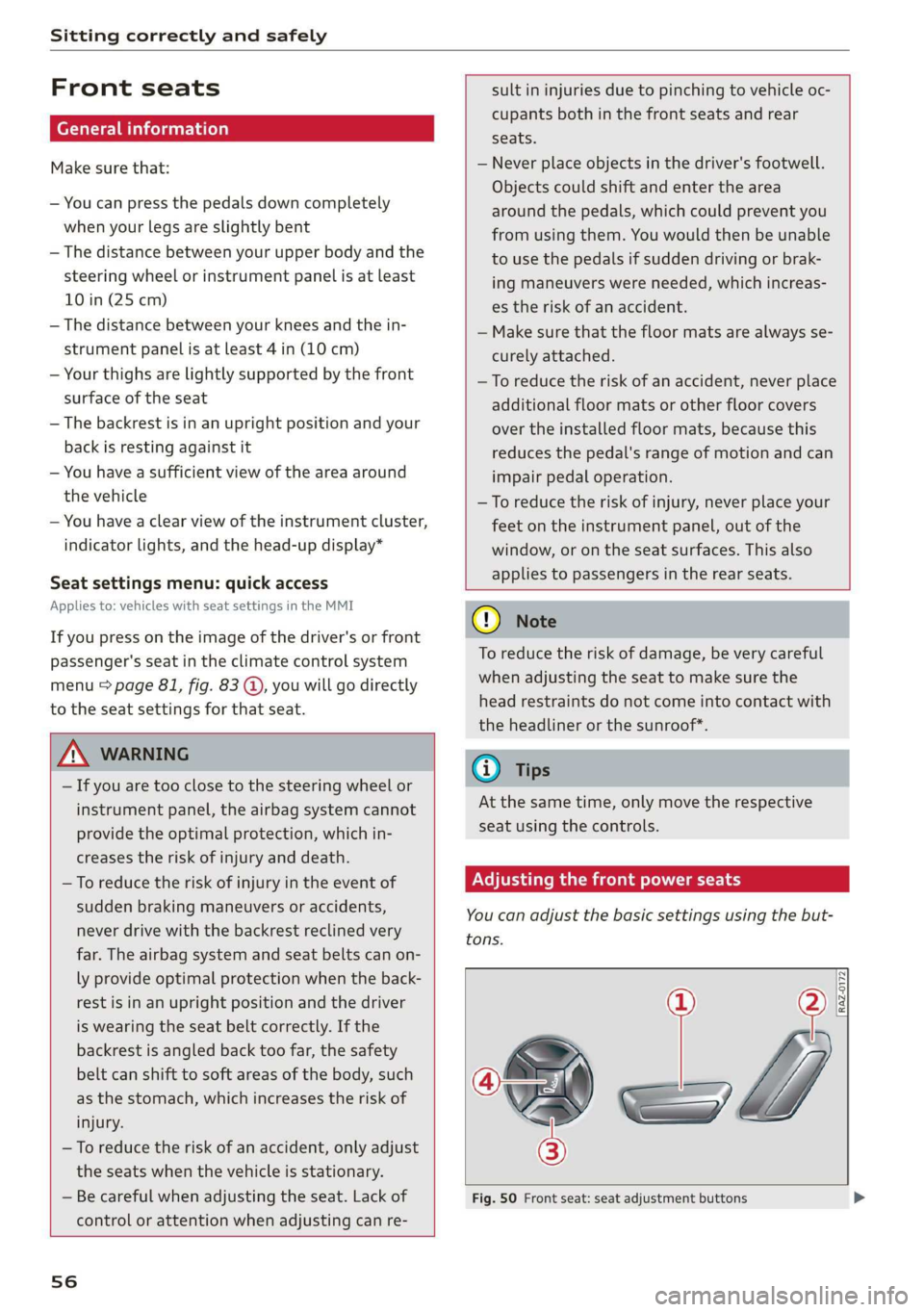
Adjusting the front power seats
You
can adjust the basic settings using the but-
RAZ-0172
tons.
(C—
s =
Fig. 50 Front seat: seat adjustment buttons
Page 60 of 310
Sitting correctly and safely
Neer t Cela eae iale MU ME
You can adjust additional settings and switch
functions on or off in the MMI.
> Applies to: MMI: Select on the home screen:
VEHICLE > Seats > Additional seat settings.
Depending on the vehicle equipment, the follow-
ing options may be available.
Reset seat position
You can adjust the position of the front passeng-
er’s seat to match the driver's seat.
Driver's seat entry assistance
Entry assistance makes it easier to enter or exit
the vehicle. The steering column will automati-
cally move upward > page 59.
Requirement: the ignition must be switched off.
The driver's seat moves back when the driver’
door is opened. Some of the air in the side bol-
sters may be released.
Front passenger's seat entry assistance
Entry assistance makes it easier to enter or exit
the vehicle.
Requirement: the ignition must be switched off.
The front passenger's seat moves back when the
front passenger’ door is opened. Some of the air
in the side bolsters may be released.
Adjusting the front passenger's seat from
the driver's seat
Applies to: vehicles with front passenger seat adjustment
You can adjust the front passenger's side with the
driver's seat buttons.
Applies to: MMI:
> Select on the home screen: VEHICLE > Seats.
> To display the various seats, press ) or <.
> To switch on the function, press the 2/ button.
The lower edge of the button will turn red.
After you have switched on the function, you can
adjust the front passenger's seat using the driv-
er's seat buttons > page 56, fig. 50.
58
G) Tips
The function switches off automatically when
you exit the menu.
claim ler- eet
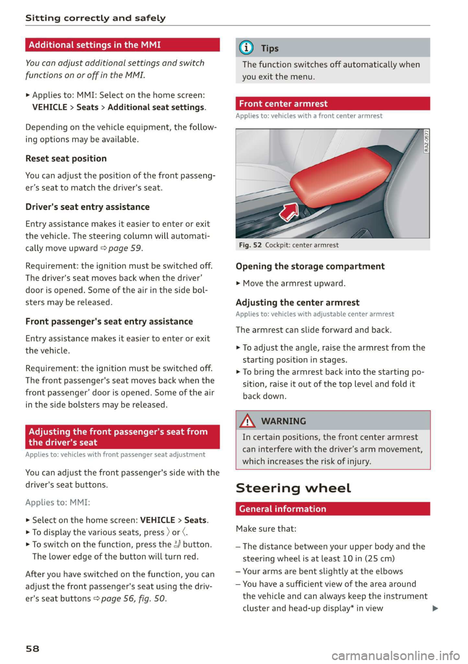
Applies to: vehicles with a front center armrest
Opening the storage compartment
> Move the armrest upward.
Adjusting the center armrest
Applies to: vehicles with adjustable center armrest
The armrest can slide forward and back.
> To adjust the angle, raise the armrest from the
starting position in stages.
> To bring the armrest back into the starting po-
sition, raise it out of the top level and fold it
back down.
ZA WARNING
In certain positions, the front center armrest
can interfere with the driver’s arm movement,
which increases the risk of injury.
Steering wheel
General information
Make sure that:
— The distance between your upper body and the
steering wheel is at least 10 in (25 cm)
— Your arms are bent slightly at the elbows
— You have a sufficient view of the area around
the vehicle and can always keep the instrument
cluster and head-up display* in view
Page 67 of 310
4KE012721BB
Sitting correctly and safely
airbags deploy from the seat backrest, such
covers could impair the protective function
of the side airbags.
Damage to the original seat covers in the
side airbag deployment area must always be
repaired by an authorized Audi dealer or au-
thorized Audi Service Facility.
Airbag system components are installed at
various locations in your vehicle. Incorrect
work or repairs on the vehicle could damage
the airbag system components or impair
their functionality. This may prevent the air-
bags from deploying or cause them to de-
ploy incorrectly in the event of an accident,
which increases the risk of serious or fatal
injuries. Only have an authorized Audi dealer
or authorized Audi Service Facility make re-
pairs or modifications to a vehicle.
The airbag system can only provide protec-
tion during one collision. If there is another
collision, the airbag system will not deploy
again. If the airbag system has deployed,
have it replaced immediately by an author-
ized Audi dealer or authorized Audi Service
Facility.
Fine dust may appear if the airbags deploy.
This is completely normal and does not indi-
cate a fire in the vehicle. The fine dust can ir-
ritate the skin and mucous membranes in
the eyes and can cause difficulty breathing,
particularly for individuals who have or have
had asthma or other health issues that af-
fect breathing. Exit the vehicle or open the
windows or doors to get access to fresh air.
(i) Tips
If you are transporting children in the vehicle,
read
the information and follow the safety
precautions > page 69.
Safety systems monitoring
The 2] indicator light in the instrument cluster
monitors the safety systems such as the airbags
(including the control modules, sensors, and wir-
ing) and the belt tensioners. It turns on when you
switch the ignition on and turns off after several
seconds.
If the ka indicator light does not turn on when
the ignition is switched on, does not turn off af-
ter several seconds, or turns on or flashes while
driving, there may be a malfunction in one of the
safety systems. Drive to an authorized Audi deal-
er or authorized Audi Service Facility immediately
to have the malfunction corrected.
ZA\ WARNING
Have the malfunction in the safety systems in-
spected immediately. Otherwise, there is a
risk that the systems may not activate during
an accident, which increases the risk of seri-
ous or fatal injury.
65
Page 69 of 310
4KE012721BB
Sitting correctly and safely
The airbag is filled by a gas generator when it de-
ploys. When this occurs, the airbag covers open
and the airbags unfold with great force into the
deployment zone within milliseconds.
Airbags lessen the movement of passengers in
the direction of the impact and thus help to re-
duce the risk of injury. They can help to protect
the head, upper body, and lap, for example. How-
ever, there is the possibility that airbag deploy-
ment can cause injuries.
The airbag system only works when the ignition
is turned on.
If you or other vehicle passengers have physical
limitations that prevent sitting in a correct posi-
tion, modifications to the vehicle may be neces-
sary. For more information, contact an author-
ized Audi dealer or authorized Audi Service Facili-
ty, or call Audi customer support at
1-800-822-2834.
G@) Tips
The side curtain airbags in your vehicle have
ejection mitigation functions. This reduces
the risk of being ejected from the vehicle inte-
rior during an accident, especially in the event
of a vehicle rollover.
Advanced airbag system
(Ri A Gasca cae) Ones \, e
[sr
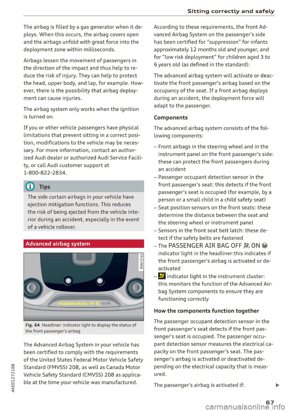
Fig. 64 Headliner: indicator light to display the status of
the front passenger's airbag
The Advanced Airbag System in your vehicle has
been certified to comply with the requirements
of the United States Federal Motor Vehicle Safety
Standard (FMVSS) 208, as well as Canada Motor
Vehicle Safety Standard (CMVSS) 208 as applica-
ble at the time your vehicle was manufactured.
According to these requirements, the front Ad-
vanced Airbag System on the passenger’s side
has been certified for “suppression” for infants
approximately 12 months old and younger, and
for “low risk deployment” for children aged 3 to
6 years old (as defined in the standard).
The advanced airbag system will activate or deac-
tivate the front passenger's airbag based on the
occupancy of the seat. If a front airbag deploys
during an accident, the deployment force will
adapt to the passenger.
Components
The advanced airbag system consists of the fol-
lowing components:
— Front airbags in the steering wheel and in the
instrument panel on the front passenger's side:
these can protect the front passengers during
an accident
— Passenger occupant detection sensor in the
front passenger's seat: this detects if the front
passenger's seat is occupied (for example, by a
person or a small child in a child safety seat)
— Seat position sensors on the front seats: these
determine the distance between the seat and
the steering wheel or instrument panel
— Sensors in the front seat belt latch: these de-
tect if the safety belts are fastened
—The PASSENGER AIR BAG OFF %; ON @
indicator light in the headliner:this indicates if
the front passenger's airbag is activated or de-
activated
- Ea indicator light in the instrument cluster:
this monitors the function of the Advanced Air-
bag System components to ensure they are
functioning correctly
How the components function together
The passenger occupant detection sensor in the
front passenger's seat detects if the front pas-
senger's seat is occupied. The passenger occu-
pant detection sensor measures the electrical ca-
pacity on the front passenger’s seat. The pas-
senger's airbag is activated or deactivated de-
pending on the electrical capacity that is meas-
ured.
The passenger's airbag is activated if:
67
Page 110 of 310
High-voltage system
Charging
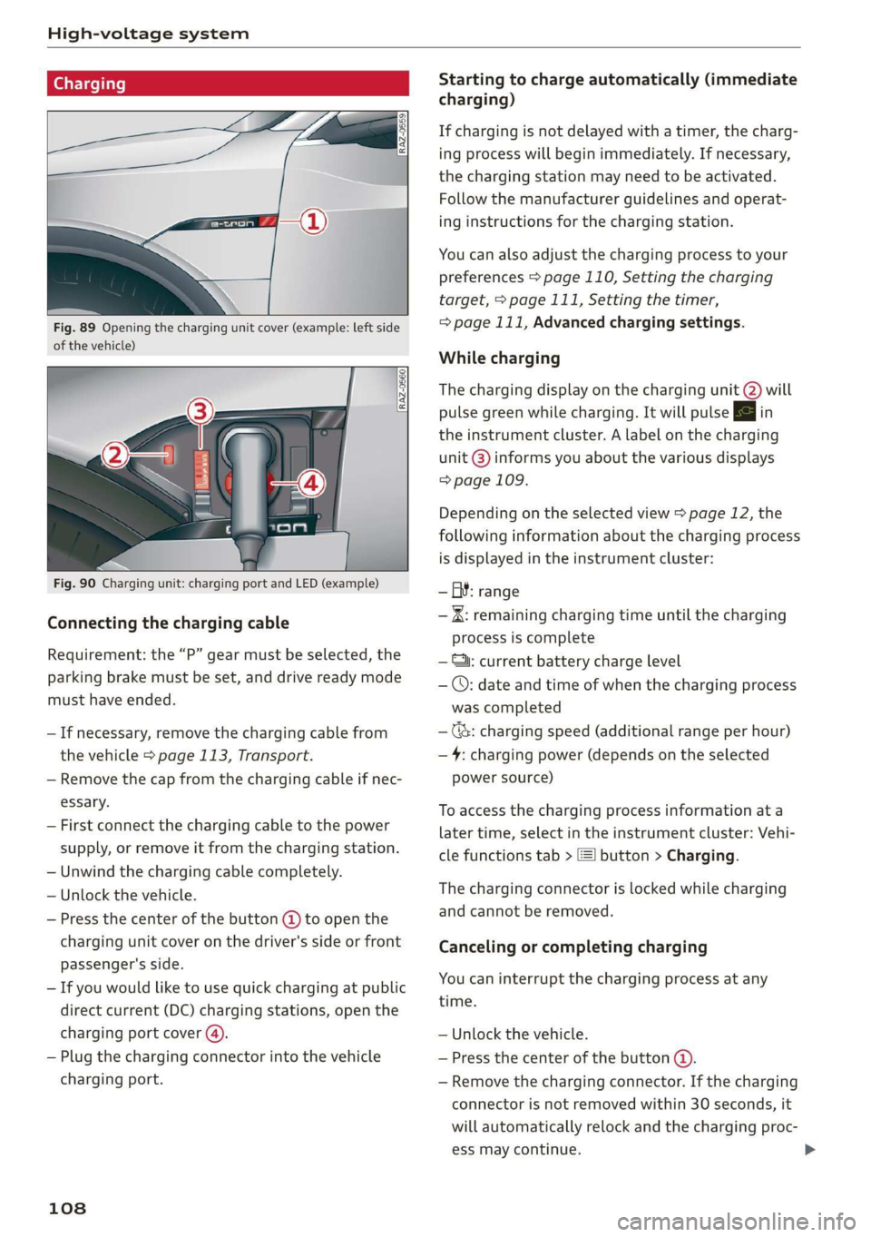
Fig. 89 Opening the charging unit cover (example: left side
of the vehicle)
Fig. 90 Charging unit: charging port and LED (example)
Connecting the charging cable
Requirement: the “P” gear must be selected, the
parking brake must be set, and drive ready mode
must have ended.
— If necessary, remove the charging cable from
the vehicle > page 113, Transport.
— Remove the cap from the charging cable if nec-
essary.
— First connect the charging cable to the power
supply, or remove it from the charging station.
— Unwind the charging cable completely.
— Unlock the vehicle.
— Press the center of the button @ to open the
charging unit cover on the driver's side or front
passenger's side.
— If you would like to use quick charging at public
direct current (DC) charging stations, open the
charging port cover (4).
— Plug the charging connector into the vehicle
charging port.
108
Starting to charge automatically (immediate
charging)
If charging is not delayed with a timer, the charg-
ing process will begin immediately. If necessary,
the charging station may need to be activated.
Follow the manufacturer guidelines and operat-
ing instructions for the charging station.
You can also adjust the charging process to your
preferences > page 110, Setting the charging
target, > page 111, Setting the timer,
=> page 111, Advanced charging settings.
While charging
The charging display on the charging unit @) will
pulse green while charging. It will pulse & in
the instrument cluster. A label on the charging
unit @) informs you about the various displays
=> page 109.
Depending on the selected view > page 12, the
following information about the charging process
is displayed in the instrument cluster:
— GY: range
— IK: remaining charging time until the charging
process is complete
— ©: current battery charge level
— ©: date and time of when the charging process
was completed
—(&: charging speed (additional range per hour)
—4: charging power (depends on the selected
power source)
To access the charging process information at a
later time, select in the instrument cluster: Vehi-
cle functions tab > [=] button > Charging.
The charging connector is locked while charging
and cannot be removed.
Canceling or completing charging
You can interrupt the charging process at any
time.
— Unlock the vehicle.
— Press the center of the button @.
— Remove the charging connector. If the charging
connector is not removed within 30 seconds, it
will automatically relock and the charging proc-
ess may continue.
Page 130 of 310
Driving information
Driving information
Speed warning system
Applies to: vehicles with speed warning system
The speed warning system helps the driver to
stay below a specified maximum speed. A warn-
ing threshold can be set in the MMI for this pur-
pose.
Once the speed slightly exceeds the stored
threshold, the speed warning system will alert
the driver with an indicator in the instrument
cluster and a warning tone. Once the speed drops
below the stored maximum speed, the indicator
will turn off.
Setting a threshold is recommended if you would
like to be reminded when you reach a certain
maximum speed. Situations where you may want
to do so include driving in a country with a gener-
al speed limit or if there is a specified maximum
speed for winter tires.
@ Tips
Regardless of the speed warning system, you
should always monitor your speed using the
speedometer and make sure you are following
the legal speed limit.
Setting the warning threshold
Applies to: vehicles with speed warning system
> Applies to: MMI: Select on the home screen:
VEHICLE > Driver assistance > (<2) > Speed
warning.
@) Tips
Specific settings are stored automatically in
the active personal profile.
Py E NY
Applies to: vehicles with speed warning system
A display appears in the instrument cluster if the
stored speed is exceeded
by Manually set XX speed limit warning
threshold exceeded
128
Camera-based traffic
sign recognition
Applies to: vehicles with camera-based traffic sign recognition
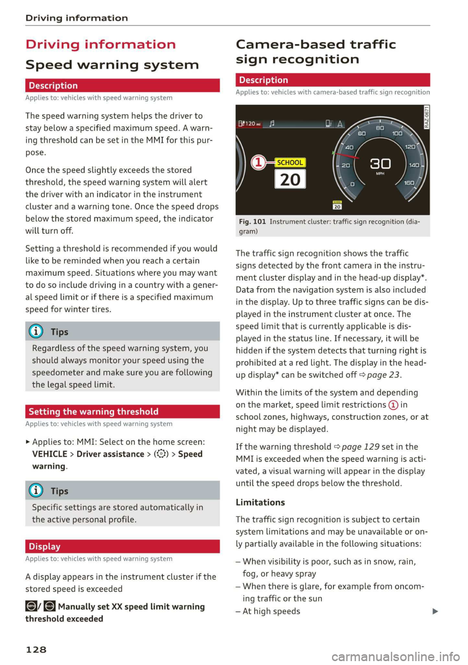
Fig. 101 Instrument cluster: traffic sign recognition (dia-
gram)
The traffic sign recognition shows the traffic
signs detected by the front camera in the instru-
ment cluster display and in the head-up display”.
Data from the navigation system is also included
in the display. Up to three traffic signs can be dis-
played in the instrument cluster at once. The
speed limit that is currently applicable is dis-
played in the status line. If necessary, it will be
hidden if the system detects that turning right is
prohibited at a red light. The display in the head-
up display* can be switched off > page 23.
Within the limits of the system and depending
on the market, speed limit restrictions @ in
school zones, highways, construction zones, or at
night may be displayed.
If the warning threshold > page 129 set in the
MMI is exceeded when the speed warning is acti-
vated, a visual warning will appear in the display
until the speed drops below the threshold.
Limitations
The traffic sign recognition is subject to certain
system limitations and may be unavailable or on-
ly partially available in the following situations:
— When visibility is poor, such as in snow, rain,
fog, or heavy spray
— When there is glare, for example from oncom-
ing traffic or the sun
— At high speeds
Page 131 of 310
4KE012721BB
Driving information
— If the camera's visual field > page 124 is cov-
ered, for example by dirt or stickers. Cleaning
information > page 263
— If the traffic signs are completely or partially
covered, for example by trees, snow, dirt, or
other vehicles
— If traffic signs do not conform to the standard
format
— If traffic signs are damaged or bent
— If traffic signs are displayed on sign holders
with electronic signs
— If the traffic signs or the roadways have
changed, and the navigation data is no longer
up-to-date
ZA\ WARNING
— Follow the safety precautions and respect
the limits of the assist systems, sensors,
and cameras > page 123.
— Under some circumstances, traffic sign rec-
ognition may not detect traffic signs correct-
ly or detect them at all. As a result, the sys-
tem may not display the correct speed limit
or any speed limit.
@ Tips
— Traffic sign recognition does not adapt your
vehicle's speed to match the speed limit.
— The display in the instrument cluster is
based on the units of measurement used for
speed in the country where the vehicle is be-
ing operated. As a result, a display of 50 in
the instrument cluster can mean either mph
or km/h, depending on the country.
Applies to: vehicles with camera-based traffic sign recognition
Accessing traffic sign recognition
> Select in the instrument cluster: vehicle func-
tions tab > Traffic signs.
Setting a traffic sign based speed warning
> Applies to: MMI: Select on the home screen:
VEHICLE > Driver assistance > (<3) > Speed
warning.
You can select a warning threshold. If exceeded,
the currently detected speed limit will be dis-
played with an exclamation point and it will flash
briefly.
@ Tips
Specific settings are stored automatically in
the active personal profile.
Messages
Applies to: vehicles with camera-based traffic sign recognition
Traffic sign recognition: currently unavaila-
ble. Camera view limited due to surroundings
The camera’s visual field is covered. Clean the
windshield.
Traffic sign recognition: currently limited.
See owner's manual
This message appears if navigation system data
is not available, for example on newly-construct-
ed roads. The speed limit display will be tempo-
rarily limited, which increases the risk of an incor-
rect display. If this message continues to appear,
drive immediately to an authorized Audi dealer or
authorized Audi Service Facility to have the mal-
function repaired.
No traffic sign information available
Depending on the area, there is no valid naviga-
tion data and no speed limits were detected. This
may also appear if there is a recommended
speed, but no speed limit (for example when
driving on and off the expressway).
Malfunction! See owner's manual
The system may not function correctly so it has
been switched off. See an authorized Audi dealer
or authorized Audi Service Facility for assistance.
Function currently unavailable. See owner's
manual
If this message appears on vehicles without cam-
era-based traffic sign recognition, then the traffic
light
information function is currently unavaila-
ble. Refer to > page 131.
129
Page 132 of 310
Driving information
Traffic light information
Applies to: vehicles with traffic light information
iS
S| >|
| ce|
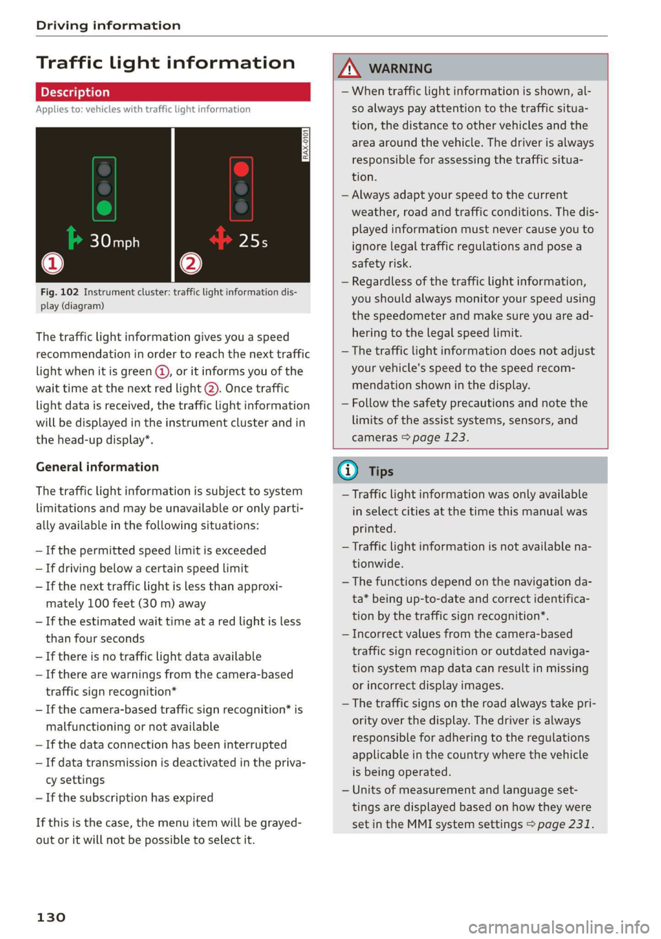
Fig. 102 Instrument cluster: traffic light information dis-
play (diagram)
The traffic light information gives you a speed
recommendation in order to reach the next traffic
light when it is green @, or it informs you of the
wait time at the next red light @). Once traffic
light data is received, the traffic light information
will be displayed in the instrument cluster and in
the head-up display*.
General information
The traffic light information is subject to system
limitations and may be unavailable or only parti-
ally available in the following situations:
— If the permitted speed limit is exceeded
— If driving below a certain speed limit
— If the next traffic light is less than approxi-
mately 100 feet (30 m) away
— If the estimated wait time at a red light is less
than four seconds
—If there is no traffic light data available
— If there are warnings from the camera-based
traffic sign recognition*
— If the camera-based traffic sign recognition* is
malfunctioning or not available
— If the data connection has been interrupted
— If data transmission is deactivated in the priva-
cy settings
— If the subscription has expired
If this is the case, the menu item will be grayed-
out or it will not be possible to select it.
130
ZA\ WARNING
— When traffic light information is shown, al-
so always pay attention to the traffic situa-
tion, the distance to other vehicles and the
area around the vehicle. The driver is always
responsible for assessing the traffic situa-
tion.
— Always adapt your speed to the current
weather, road and traffic conditions. The dis-
played information must never cause you to
ignore legal traffic regulations and pose a
safety risk.
— Regardless of the traffic light information,
you should always monitor your speed using
the speedometer and make sure you are ad-
hering to the legal speed limit.
— The traffic light information does not adjust
your vehicle's speed to the speed recom-
mendation shown in the display.
— Follow the safety precautions and note the
limits of the assist systems, sensors, and
cameras > page 123.
@) Tips
— Traffic light information was only available
in select cities at the time this manual was
printed.
— Traffic light information is not available na-
tionwide.
— The functions depend on the navigation da-
ta* being up-to-date and correct identifica-
tion by the traffic sign recognition*.
— Incorrect values from the camera-based
traffic sign recognition or outdated naviga-
tion system map data can result in missing
or incorrect display images.
— The traffic signs on the road always take pri-
ority over the display. The driver is always
responsible for adhering to the regulations
applicable in the country where the vehicle
is being operated.
— Units of measurement and language set-
tings are displayed based on how they were
set in the MMI system settings > page 231.