tire AUDI E-TRON 2019 User Guide
[x] Cancel search | Manufacturer: AUDI, Model Year: 2019, Model line: E-TRON, Model: AUDI E-TRON 2019Pages: 310, PDF Size: 81.91 MB
Page 121 of 310
4KE012721BB
High-voltage system
> Tighten the screw (3) using the screwdriver pro-
vided.
ZA\ WARNING
— Note the warnings for charging > A in
Charging on page 109.
— Before switching the power cable, always
unplug the power cable from the socket.
— Only change cables in a dry environment.
— The Audi charging system may only be used
as a complete unit consisting of the power
cables, the control unit, and the vehicle ca-
ble. We recommend using only cables ap-
proved by Audi.
i) Tips
The power cable with the power connector for
industrial sockets and the Audi charging sys-
tem control unit are designed to work togeth-
er. Changing the power cable to another con-
nector type may reduce the available charging
power of the entire system.
Wall mount clip
Applies to: vehicles with wall mount clip
RAZ-0638
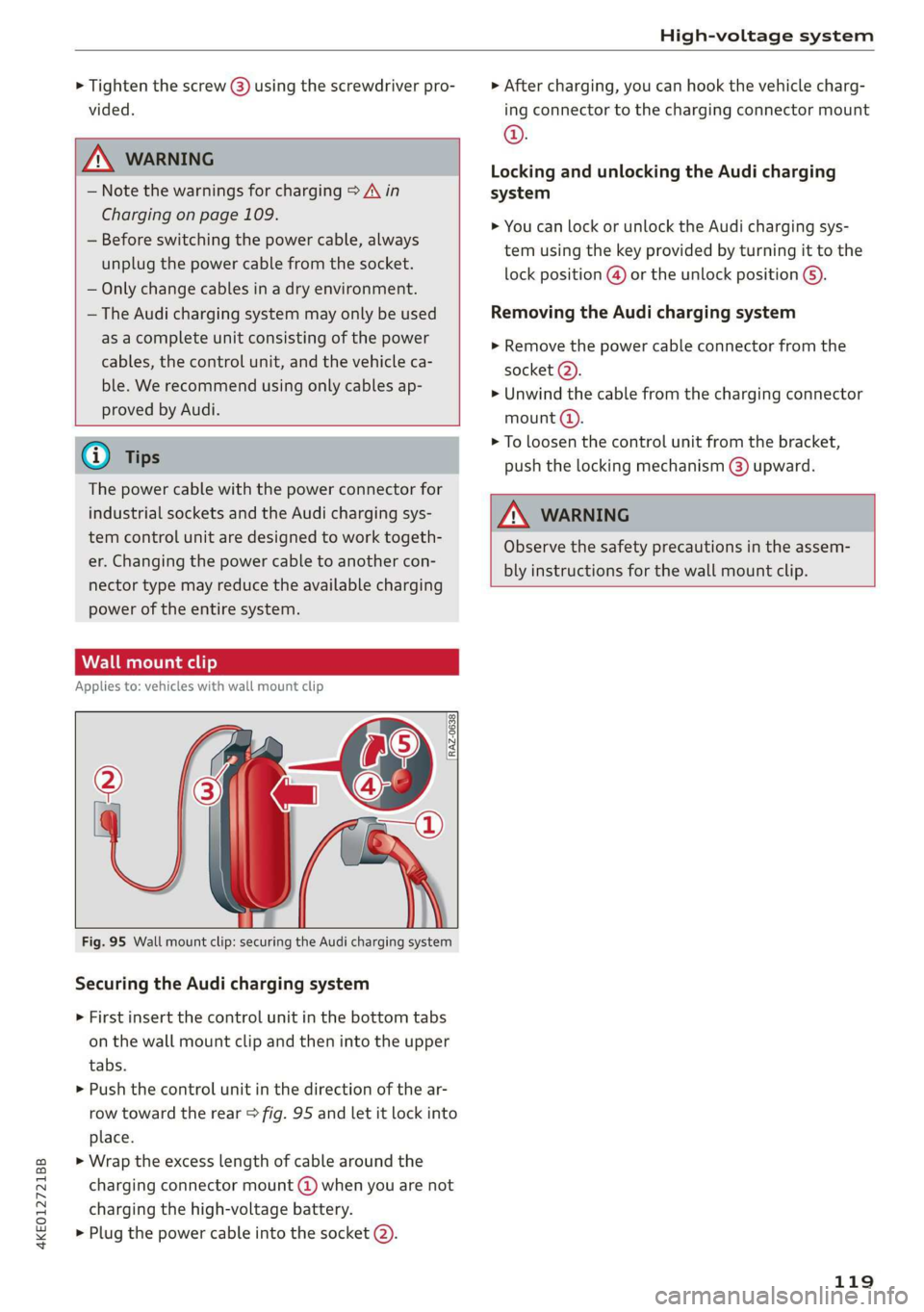
Fig. 95 Wall mount clip: securing the Audi charging system
Securing the Audi charging system
> First insert the control unit in the bottom tabs
on the wall mount clip and then into the upper
tabs.
> Push the control unit in the direction of the ar-
row toward the rear > fig. 95 and let it lock into
place.
> Wrap the excess length of cable around the
charging connector mount @) when you are not
charging the high-voltage battery.
> Plug the power cable into the socket (2).
> After charging, you can hook the vehicle charg-
ing connector to the charging connector mount
©.
Locking and unlocking the Audi charging
system
> You can lock or unlock the Audi charging sys-
tem using the key provided by turning it to the
lock position @) or the unlock position 6).
Removing the Audi charging system
> Remove the power cable connector from the
socket (2).
» Unwind the cable from the charging connector
mount @).
> To loosen the control unit from the bracket,
push the locking mechanism (@) upward.
ZA\ WARNING
Observe the safety precautions in the assem-
bly instructions for the wall mount clip.
119
Page 123 of 310
4KE012721BB
Trailer towing
The permitted tongue weight of your vehicle can
be found in the vehicle documentation or in
=> page 292.
Load distribution
Poor cargo load and distribution can negatively
impact vehicle handling. Load the trailer based
on the following criteria as much as possible:
— Store objects in the vehicle luggage compart-
ment, if possible. The vehicle should always
carry the heaviest possible load and the trailer
should have the lightest possible load.
— Distribute the load in the trailer so that the
heavy objects are as close to the axle as possi-
ble.
— Secure objects so that they do not slide.
— Utilize the maximum permitted tongue weight
if possible.
Tires
Set the tire pressure on your vehicle for a “full
load”; see the tire pressure sticker > page 253. If
necessary, also adjust the tire pressure on the
trailer according to the manufacturer's specifica-
tions.
The trailer and the vehicle should be equipped
with winter tires when driving in winter tempera-
tures.
Outside mirrors
If you cannot see the traffic behind the trailer
with the standard exterior mirrors, then you
must attach additional exterior mirrors. Adjust
them so you have a sufficient visibility behind
you.
Exterior lighting
Follow the legal regulations for lighting on your
trailer that are applicable in the country where
you are operating the vehicle. Contact an author-
ized Audi dealer or authorized Audi Service Facili-
ty for more information.
Before you start driving, check all lighting equip-
ment on the trailer while it is hitched to the vehi-
cle.
The headlight range control automatically ad-
justs the light range of the headlights.
Safety chains
Make sure the safety chains are correctly applied
when pulling a trailer. The chains should hang
enough so that the trailer can drive around
curves. However, they must not touch the
ground.
Air suspension
The Audi drive select* comfort mode > page 98
must be selected before you adjust the tongue
weight on the trailer and hitch the trailer >@,
=> page 99.
For vehicles with a retrofitted trailer hitch, you
must switch on the air suspension trailer mode
manually.
Applies to: MMI: Select on the home screen: VE-
HICLE > Settings & Service > Air suspension:
trailer.
Switch it off again when you are no longer towing
a trailer.
When using carrier systems that are mounted di-
rectly on the trailer hitch ball head, you can also
switch trailer mode off manually.
If you must drive on roads that are in poor condi-
tion, you can raise the vehicle again after hitching
the trailer or after adjusting the tongue weight
> page 99.
You can also increase ground clearance by select-
ing the Audi drive select* offroad or allroad
modes > page 98.
Vehicle levels below the values set in the comfort
level will no Longer be available, even if you are
lowering the vehicle manually.
ZA WARNING
— Never turn off trailer mode while driving
when a trailer is hitched, because then the
restrictions for controlling the vehicle level
will be turned off.
— Driving with a trailer on unpaved roads when
the vehicle is raised may change the vehicle
handling. Adapt your speed.
121
Page 126 of 310
Assist systems
Surrounding area
detection
Sensor overview
RAZ-06T1
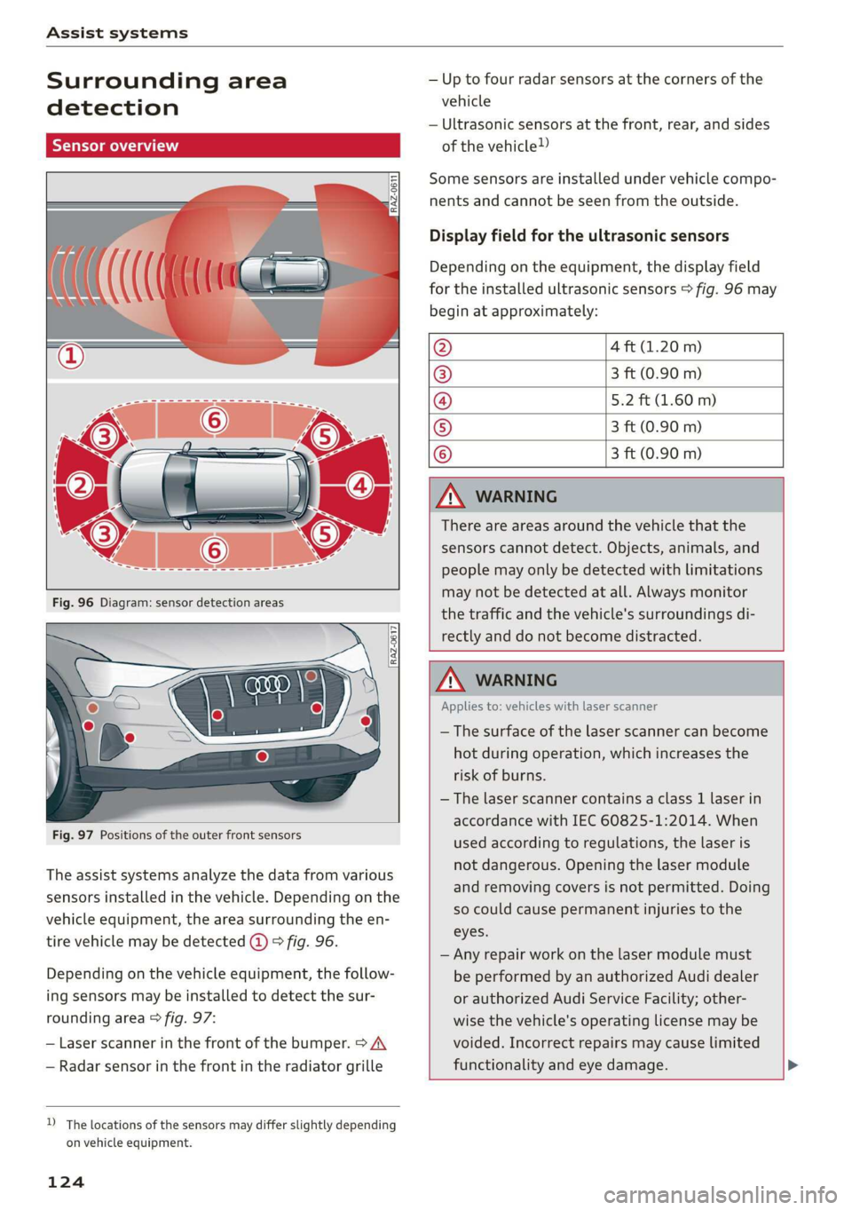
Fig. 97 Positions of the outer front sensors
The assist systems analyze the data from various
sensors installed in the vehicle. Depending on the
vehicle equipment, the area surrounding the en-
tire vehicle may be detected @ 9 fig. 96.
Depending on the vehicle equipment, the follow-
ing sensors may be installed to detect the sur-
rounding area > fig. 97:
— Laser scanner in the front of the bumper. > A\
— Radar sensor in the front in the radiator grille
D_ The locations of the sensors may differ slightly depending
on vehicle equipment.
124
— Up to four radar sensors at the corners of the
vehicle
— Ultrasonic sensors at the front, rear, and sides
of the vehicle!)
Some sensors are installed under vehicle compo-
nents and cannot be seen from the outside.
Display field for the ultrasonic sensors
Depending on the equipment, the display field
for the installed ultrasonic sensors > fig. 96 may
begin at approximately:
@ 4 ft (1.20 m)
® 3 ft (0.90 m)
@ 5.2 ft (1.60 m)
® 3 ft (0.90 m)
© 3 ft (0.90 m)
ZA\ WARNING
There are areas around the vehicle that the
sensors cannot detect. Objects, animals, and
people may only be detected with limitations
may not be detected at all. Always monitor
the traffic and the vehicle's surroundings di-
rectly and do not become distracted.
ZA WARNING
Applies to: vehicles with laser scanner
— The surface of the laser scanner can become
hot during operation, which increases the
risk of burns.
— The laser scanner contains a class 1 laser in
accordance with IEC 60825-1:2014. When
used according to regulations, the laser is
not dangerous. Opening the laser module
and removing covers is not permitted. Doing
so could cause permanent injuries to the
eyes.
— Any repair work on the laser module must
be performed by an authorized Audi dealer
or authorized Audi Service Facility; other-
wise the vehicle's operating license may be
voided. Incorrect repairs may cause limited
functionality and eye damage.
Page 130 of 310
Driving information
Driving information
Speed warning system
Applies to: vehicles with speed warning system
The speed warning system helps the driver to
stay below a specified maximum speed. A warn-
ing threshold can be set in the MMI for this pur-
pose.
Once the speed slightly exceeds the stored
threshold, the speed warning system will alert
the driver with an indicator in the instrument
cluster and a warning tone. Once the speed drops
below the stored maximum speed, the indicator
will turn off.
Setting a threshold is recommended if you would
like to be reminded when you reach a certain
maximum speed. Situations where you may want
to do so include driving in a country with a gener-
al speed limit or if there is a specified maximum
speed for winter tires.
@ Tips
Regardless of the speed warning system, you
should always monitor your speed using the
speedometer and make sure you are following
the legal speed limit.
Setting the warning threshold
Applies to: vehicles with speed warning system
> Applies to: MMI: Select on the home screen:
VEHICLE > Driver assistance > (<2) > Speed
warning.
@) Tips
Specific settings are stored automatically in
the active personal profile.
Py E NY
Applies to: vehicles with speed warning system
A display appears in the instrument cluster if the
stored speed is exceeded
by Manually set XX speed limit warning
threshold exceeded
128
Camera-based traffic
sign recognition
Applies to: vehicles with camera-based traffic sign recognition
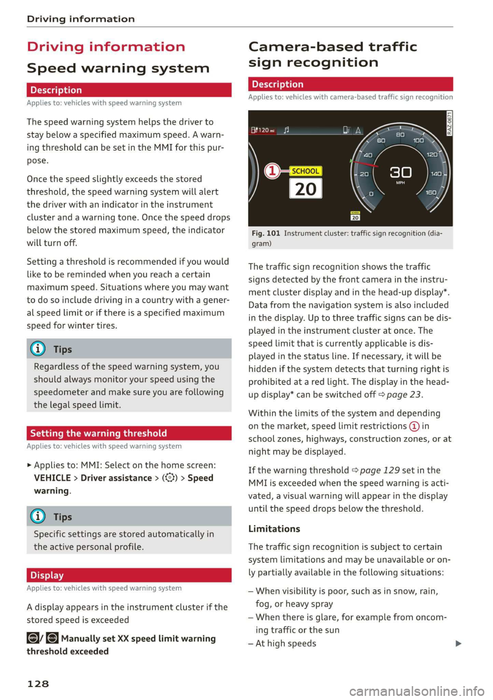
Fig. 101 Instrument cluster: traffic sign recognition (dia-
gram)
The traffic sign recognition shows the traffic
signs detected by the front camera in the instru-
ment cluster display and in the head-up display”.
Data from the navigation system is also included
in the display. Up to three traffic signs can be dis-
played in the instrument cluster at once. The
speed limit that is currently applicable is dis-
played in the status line. If necessary, it will be
hidden if the system detects that turning right is
prohibited at a red light. The display in the head-
up display* can be switched off > page 23.
Within the limits of the system and depending
on the market, speed limit restrictions @ in
school zones, highways, construction zones, or at
night may be displayed.
If the warning threshold > page 129 set in the
MMI is exceeded when the speed warning is acti-
vated, a visual warning will appear in the display
until the speed drops below the threshold.
Limitations
The traffic sign recognition is subject to certain
system limitations and may be unavailable or on-
ly partially available in the following situations:
— When visibility is poor, such as in snow, rain,
fog, or heavy spray
— When there is glare, for example from oncom-
ing traffic or the sun
— At high speeds
Page 167 of 310
4KE012721BB
Parking and maneuvering
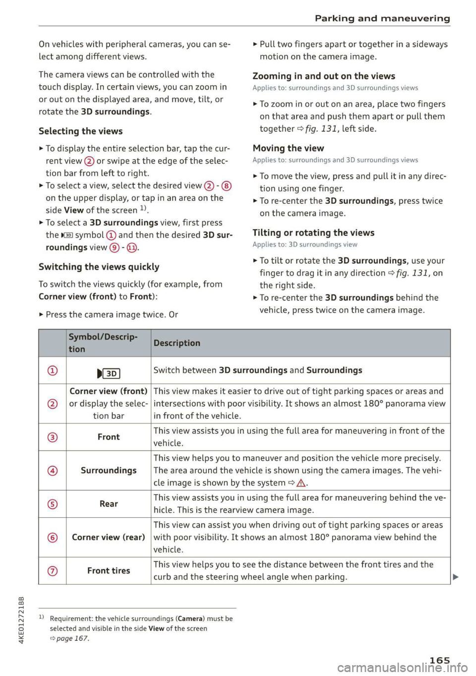
On vehicles with peripheral cameras, you can se-
lect among different views.
The camera views can be controlled with the
touch display. In certain views, you can zoom in
or out on the displayed area, and move, tilt, or
rotate the 3D surroundings.
Selecting the views
> To display the entire selection bar, tap the cur-
rent view (2) or swipe at the edge of the selec-
tion bar from left to right.
> To select a view, select the desired view @) -
on the upper display, or tap in an area on the
side View of the screen )).
> To select a 3D surroundings view, first press
the Gal symbol (@) and then the desired 3D sur-
roundings view ©) - @.
Switching the views quickly
To switch the views quickly (for example, from
Corner view (front) to Front):
> Press the camera image twice. Or
> Pull two fingers apart or together in a sideways
motion on the camera image.
Zooming in and out on the views
Applies to: surroundings and 3D surroundings views
> To zoom in or out on an area, place two fingers
on that area and push them apart or pull them
together > fig. 131, left side.
Moving the view
Applies to: surroundings and 3D surroundings views
> To move the view, press and pull it in any direc-
tion using one finger.
> To re-center the 3D surroundings, press twice
on the camera image.
Tilting or rotating the views
Applies to: 3D surroundings view
> To tilt or rotate the 3D surroundings, use your
finger to drag it in any direction > fig. 131, on
the right side.
> To re-center the 3D surroundings behind the
vehicle, press twice on the camera image.
Symbol/Descrip-
Description
tion P
ED)
Switch between 3D surroundings and Surroundings
Corner view (front) | This view makes it easier to drive out of tight parking spaces or areas and
or display the selec-
tion bar
intersections with poor visibility. It shows an almost 180° panorama view
in front of the vehicle.
Front
This view assists you in using the full area for maneuvering in front of the
vehicle.
Surroundings
This view helps you to maneuver and position the vehicle more precisely.
The area around the vehicle is shown using the camera images. The vehi-
cle image is shown by the system > A\.
Rear
This view assists you in using the full area for maneuvering behind the ve-
hicle. This is the rearview camera image.
Corner view (rear)
This view can assist you when driving out of tight parking spaces or areas
with poor visibility. It shows an almost 180° panorama view behind the
vehicle.
Ge}
©
|®;|
©
|}8)
©
|e
Front tires
This view helps you to see the distance between the front tires and the
curb and the steering wheel angle when parking.
) Requirement: the vehicle surroundings (Camera) must be
selected and visible in the side View of the screen
=> page 167.
165
Page 168 of 310
Parking and maneuvering
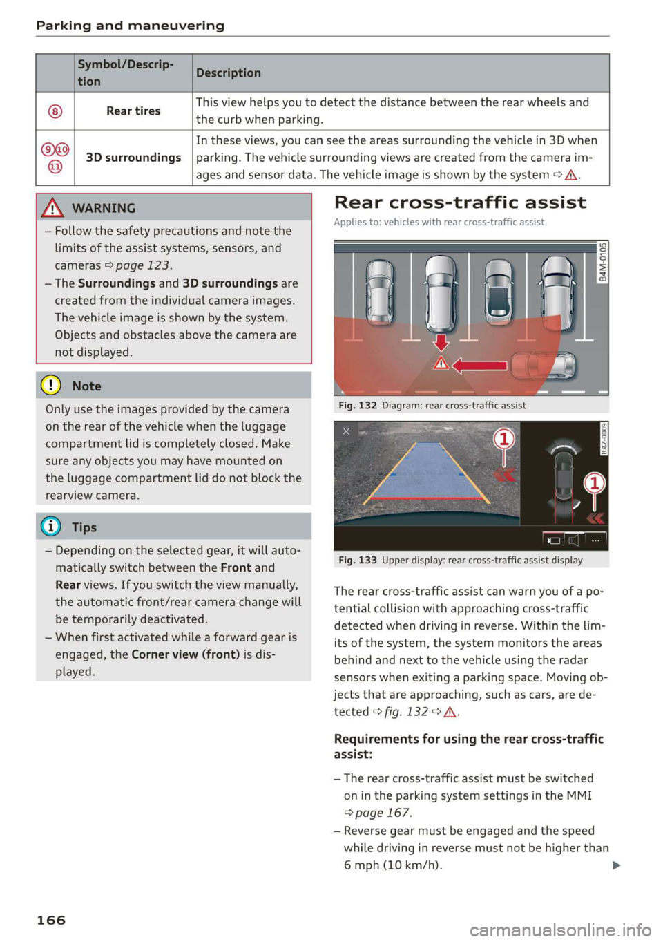
Symbol/Descrip-
Description
tion P
Rear tires
the curb when parking.
This view helps you to detect the distance between the rear wheels and
@
3D surroundings
In these views, you can see the areas surrounding the vehicle in 3D when
parking. The vehicle surrounding views are created from the camera im-
ages and sensor data. The vehicle image is shown by the system > A\.
ZX WARNING
— Follow the safety precautions and note the
limits of the assist systems, sensors, and
cameras © page 123.
— The Surroundings and 3D surroundings are
created from the individual camera images.
The vehicle image is shown by the system.
Objects and obstacles above the camera are
not displayed.
@) Note
Only use the images provided by the camera
on the rear of the vehicle when the luggage
compartment lid is completely closed. Make
sure any objects you may have mounted on
the luggage compartment lid do not block the
rearview camera.
@) Tips
— Depending on the selected gear, it will auto-
matically switch between the Front and
Rear views. If you switch the view manually,
the automatic front/rear camera change will
be temporarily deactivated.
— When first activated while a forward gear is
engaged, the Corner view (front) is dis-
played.
166
Rear cross-traffic assist
Applies to: vehicles with rear cross-traffic assist
B4M-0105
Fig. 133 Upper display: rear cross-traffic assist display
The rear cross-traffic assist can warn you of a po-
tential collision with approaching cross-traffic
detected when driving in reverse. Within the lim-
its of the system, the system monitors the areas
behind and next to the vehicle using the radar
sensors when exiting a parking space. Moving ob-
jects that are approaching, such as cars, are de-
tected > fig. 132 > A.
Requirements for using the rear cross-traffic
assist:
— The rear cross-traffic assist must be switched
on in the parking system settings in the MMI
=> page 167.
— Reverse gear must be engaged and the speed
while driving in reverse must not be higher than
6 mph (10 km/h).
Page 210 of 310
Navigation
Map colors
— Automatic: the map display adapts to the light-
ing conditions (for example, by changing from
day to night when driving through a tunnel).
— Day or Night
Map orientation
— 2D map or 2D north up: the current vehicle po-
sition is displayed. The map is oriented in the
direction of travel or to the north.
— 3D map: the current vehicle position is shown
on a three-dimensional map and is oriented in
the direction of travel.
— Overview: the entire route from the vehicle po-
sition to the destination or the next stopover is
displayed on the map. The map is oriented to
the north.
Automatic zoom
— On: the map scale is adapted automatically de-
pending on the type of road being traveled (ex-
pressway, highway, other roads) so that you al-
ways have an optimal overview of the road
ahead. When route guidance is active, the scale
is adjusted automatically for a better detailed
view when there are upcoming maneuvers.
— Intersection: when route guidance is active, the
scale is adjusted automatically for a better de-
tailed view when there are upcoming maneu-
vers.
— Off
MMI map contents: you can switch the display of
additional information (such as POIs) on the map
in the upper display on or off.
— Always follow >@ for the following map con-
tent:
— 3D city model
— The weather forecast is displayed on a 3 mile (5
km) scale on the map.
Voice guidance
Voice guidance: you can adjust the navigation
prompts. With the Traffic setting, the MMI will
only give prompts if there are traffic incidents on
your route.
Voice guidance during phone call
208
Entertainment fader during navigation: the au-
dio playback volume is temporarily lowered when
navigation prompts are active.
Route criteria
You can adjust which route criteria should be al-
lowed or avoided for the route calculation.
HOV/carpool lanes
Highways
Toll roads
Ferries
e-tron route planner
This function can be switched on and off.
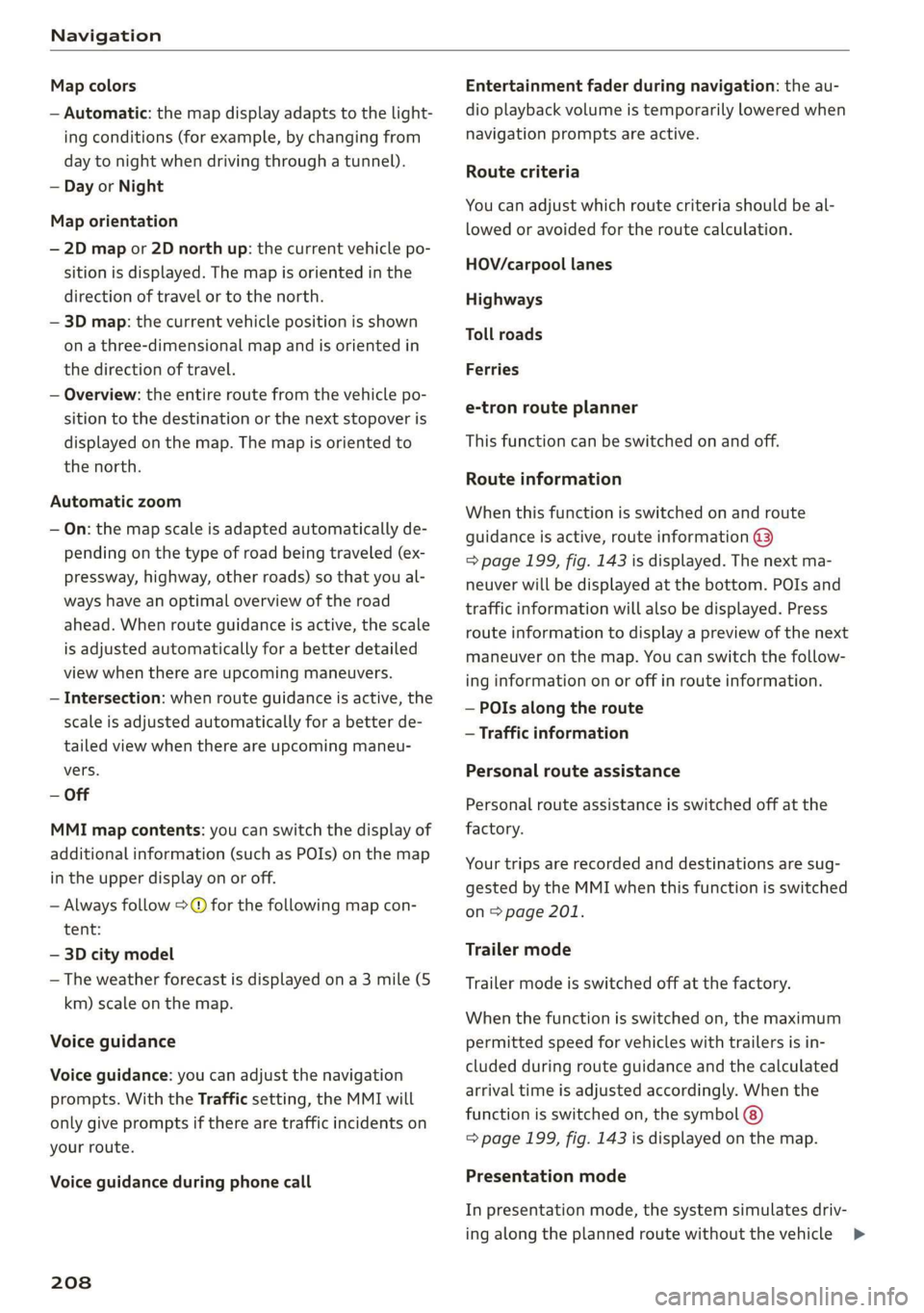
Route information
When this function is switched on and route
guidance is active, route information ®
=> page 199, fig. 143 is displayed. The next ma-
neuver will be displayed at the bottom. POIs and
traffic information will also be displayed. Press
route
information to display a preview of the next
maneuver on the map. You can switch the follow-
ing information on or off in route information.
— POIs along the route
— Traffic information
Personal route assistance
Personal route assistance is switched off at the
factory.
Your trips are recorded and destinations are sug-
gested by the MMI when this function is switched
on > page 201.
Trailer mode
Trailer mode is switched off at the factory.
When the function is switched on, the maximum
permitted speed for vehicles with trailers is in-
cluded during route guidance and the calculated
arrival time is adjusted accordingly. When the
function is switched on, the symbol @)
=> page 199, fig. 143 is displayed on the map.
Presentation mode
In presentation mode, the system simulates driv-
ing along the planned route without the vehicle >
Page 228 of 310
Media
Play
The selected track or all tracks in the folder will
be displayed.
Language!)
You can set the language manually. The language
and audio format options depend on the video
DVD.
Subtitles»)
You can manually select subtitles for playback.
The languages available depend on the DVD.
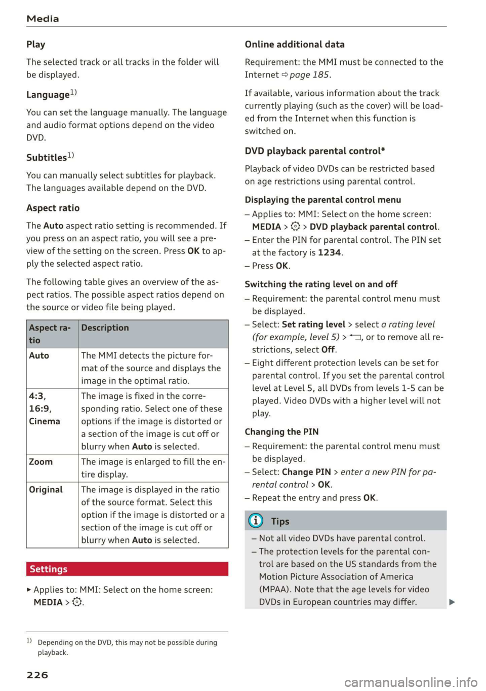
Aspect ratio
The Auto aspect ratio setting is recommended. If
you press on an aspect ratio, you will see a pre-
view of the setting on the screen. Press OK to ap-
ply the selected aspect ratio.
The following table gives an overview of the as-
pect ratios. The possible aspect ratios depend on
the source or video file being played.
Aspect ra- |Description
tio
Auto The MMI detects the picture for-
mat of the source and displays the
image in the optimal ratio.
4:3, The image is fixed in the corre-
16:9, sponding ratio. Select one of these
Cinema options if the image is distorted or
a section of the image is cut off or
blurry when Auto is selected.
Zoom The image is enlarged to fill the en-
tire display.
Original The image is displayed in the ratio
of the source format. Select this
option if the image is distorted or a
section of the image is cut off or
blurry when Auto is selected.
> Applies to: MMI: Select on the home screen:
MEDIA > ©}.
)) Depending on the DVD, this may not be possible during
playback.
226
Online additional data
Requirement: the MMI must be connected to the
Internet > page 185.
If available, various information about the track
currently playing (such as the cover) will be load-
ed from the Internet when this function is
switched on.
DVD playback parental control*
Playback of video DVDs can be restricted based
on age restrictions using parental control.
Displaying the parental control menu
— Applies to: MMI: Select on the home screen:
MEDIA > © > DVD playback parental control.
— Enter the PIN for parental control. The PIN set
at the factory is 1234.
— Press OK.
Switching the rating level on and off
— Requirement: the parental control menu must
be displayed.
— Select: Set rating level > select a rating level
(for example, level 5) > ~1, or to remove all re-
strictions, select Off.
— Eight different protection levels can be set for
parental control. If you set the parental control
level at Level 5, all DVDs from levels 1-5 can be
played. Video DVDs with a higher level will not
play.
Changing the PIN
— Requirement: the parental control menu must
be displayed.
— Select: Change PIN > enter a new PIN for pa-
rental control > OK.
— Repeat the entry and press OK.
G) Tips
— Not all video DVDs have parental control.
— The protection levels for the parental con-
trol are based on the US standards from the
Motion Picture Association of America
(MPAA). Note that the age levels for video
DVDs in European countries may differ.
Page 245 of 310
4KE012721BB
Wheels
Wheels Wheels
and Tires
General information
> Check your tires regularly for
damage, such as punctures,
cuts, cracks, and bulges. Remove
foreign objects from the tire
tread.
>If driving over curbs or similar
obstacles, drive slowly and ap-
proach the curb at an angle.
>Have faulty tires or rims re-
placed immediately.
>Protect your tires from oil and
grease.
>Mark tires before removing
them so that the same running
direction can be maintained if
they are reinstalled.
>Lay tires flat when storing and
store them ina cool, dry location
with as little exposure to light as
possible.
A WARNING
—Never drive faster than the
maximum permitted speed for
your tires. This could cause the
tires to heat up too much. This
increases the risk of an acci-
dent because it can cause the
tire to burst.
—Always adapt your driving to
the road and traffic condi-
tions. Drive carefully and re-
duce your speed on icy or slip-
pery roads. Even winter tires
can lose traction on black ice.
() Note
—Please note that summer and
winter tires are designed for
the conditions that are typical
in those seasons. Audi recom-
mends using winter tires dur-
ing the winter months. Low
temperatures significantly de-
crease the elasticity of summ-
er tires, which affects traction
and braking ability. If summer
tires are used in very cold tem-
peratures, cracks can form on
the tread bars, resulting in
permanent tire damage that
can cause loud driving noise
and unbalanced tires.
—Burnished, polished or
chromed rims must not be
used in winter driving condi-
tions. The surface of the rims
does not have sufficient corro-
sion protection for this and
could be permanently dam-
aged by road salt or similar
substances.
243
Page 246 of 310
Wheels
Tire designations
© 2 2 x ©
oO
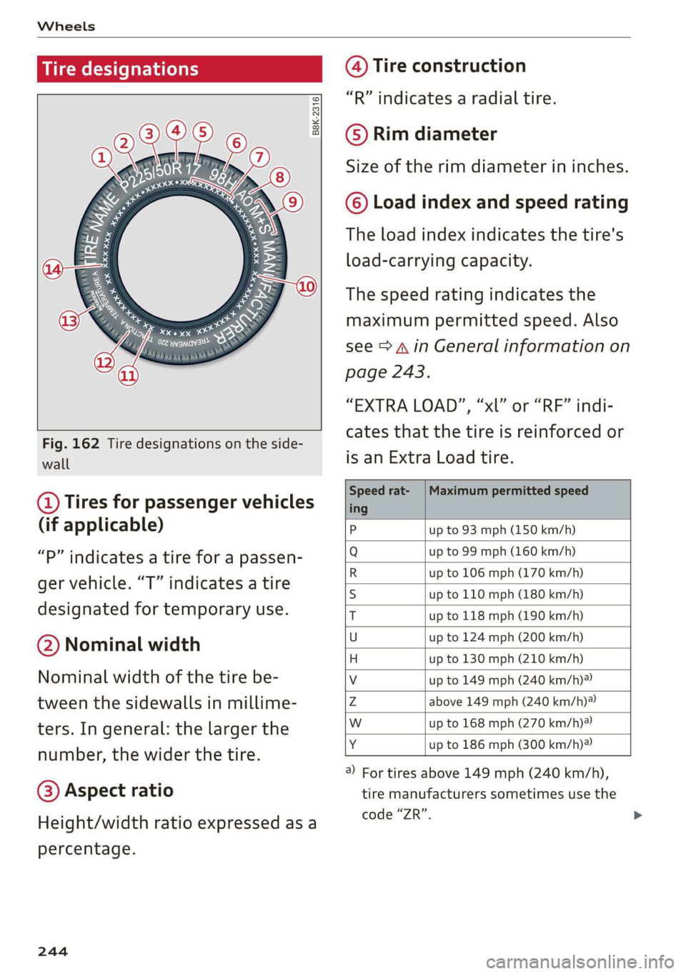
Fig. 162 Tire designations on the side-
wall
@ Tires for passenger vehicles
(if applicable)
“P” indicates a tire for a passen-
ger vehicle. “T” indicates a tire
designated for temporary use.
@ Nominal width
Nominal width of the tire be-
tween the sidewalls in millime-
ters. In general: the larger the
number, the wider the tire.
@) Aspect ratio
Height/width ratio expressed as a
percentage.
244
@) Tire construction
“R” indicates a radial tire.
©) Rim diameter
Size of the rim diameter in inches.
© Load index and speed rating
The load index indicates the tire's
load-carrying capacity.
The speed rating indicates the
maximum permitted speed. Also
see > A in General information on
page 243.
“EXTRA LOAD”, “xl” or “RF” indi-
cates that the tire is reinforced or
is an Extra Load tire.
Speed rat- /Maximum permitted speed
ing
P up to 93 mph (150 km/h)
Q up to 99 mph (160 km/h)
R up to 106 mph (170 km/h)
s up to 110 mph (180 km/h)
T up to 118 mph (190 km/h)
U up to 124 mph (200 km/h)
H up to 130 mph (210 km/h)
Vv up to 149 mph (240 km/h)?
Zz above 149 mph (240 km/h)?)
w up to 168 mph (270 km/h)?
Y up to 186 mph (300 km/h)
@) For tires above 149 mph (240 km/h),
tire manufacturers sometimes use the
code “ZR”.