tire AUDI E-TRON 2019 Service Manual
[x] Cancel search | Manufacturer: AUDI, Model Year: 2019, Model line: E-TRON, Model: AUDI E-TRON 2019Pages: 310, PDF Size: 81.91 MB
Page 271 of 310
4KE012721BB
Emergency assistance
Emergency assistance
General information
> Park the vehicle as far as possible from moving
traffic in the event of a breakdown. In the event
of a flat tire, park the vehicle ona level surface.
If you are ona steep hill, be especially careful.
> Set the parking brake.
> Switch the emergency flashers on.
> Have the passengers exit the vehicle. They
should move to a safe place, for example be-
hind a guard rail.
Z\ WARNING
Follow the steps given above. This is for your
protection and the for the safety of others on
the road.
Equipment
Vehicle tool kit, tire
vehicle jack
Applies to: vehicles with the vehicle tool kit, tire mobility kit,
and vehicle jack
yi aYaLaL eae Tale|
AZ-0636
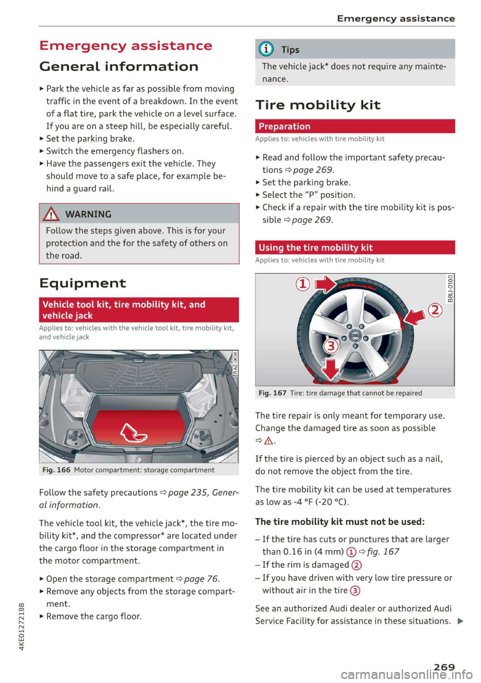
Fig. 166 Motor compartment: storage compartment
Follow the safety precautions > page 235, Gener-
al information.
The vehicle tool kit, the vehicle jack*, the tire mo-
bility kit*, and the compressor* are located under
the cargo floor in the storage compartment in
the motor compartment.
> Open the storage compartment > page 76.
> Remove any objects from the storage compart-
ment.
> Remove the cargo floor.
G) Tips
The vehicle jack* does not require any mainte-
nance.
Tire mobility kit
Applies to: vehicles with tire mobility kit
> Read and follow the important safety precau-
tions > page 269.
>» Set the parking brake.
> Select the “P” position.
> Check if a repair with the tire mobility kit is pos-
sible > page 269.
UE Raimi) LaLa
Applies to: vehicles with tire mobility kit
B8U-0100
Fig. 167 Tire: tire damage that cannot be repaired
The tire repair is only meant for temporary use.
Change the damaged tire as soon as possible
SA.
If the tire is pierced by an object such as a nail,
do not remove the object from the tire.
The tire mobility kit can be used at temperatures
as low as -4 °F (-20 °C).
The tire mobility kit must not be used:
—If the tire has cuts or punctures that are larger
than 0.16 in (4 mm) @ © fig. 167
— If the rim is damaged (2)
— If you have driven with very low tire pressure or
without air in the tire @)
See an authorized Audi dealer or authorized Audi
Service Facility for assistance in these situations. >
269
Page 272 of 310
Emergency assistance
ZA WARNING
— Please note that the tire mobility kit cannot
be used in all situations, and that it may on-
ly be used temporarily.
— The tire sealant must not come in contact
with skin, eyes, or clothing.
— If tire sealant comes into contact with your
eyes or your skin, thoroughly rinse the af-
fected area immediately with clean water.
— Do not inhale the fumes.
— If you swallow any of the tire sealant, thor-
oughly rinse your mouth immediately and
drink a lot of water. Do not induce vomiting.
Seek medical attention immediately.
— Change your clothing immediately if it
comes into contact with tire sealant.
— If an allergic reaction occurs, seek medical
attention immediately.
— Keep the tire sealant away from children.
G) Tips
— If sealant leaks, allow it to dry in place. You
can then peel it off like a sticker.
— Note the expiration date on the sealant bot-
tle. Replace the tire sealant at an authorized
Audi dealer or authorized Audi Service Fa-
cility.
— Radio reception can be interrupted when
operating the compressor.
— Follow the legal regulations that are appli-
cable in the country where you are operating
the vehicle.
D_ The compressor may look different. However, the way it is
operated is generally the same.
270
Repairing tires
Applies to: vehicles with tire mobility kit
RAZ-0213|
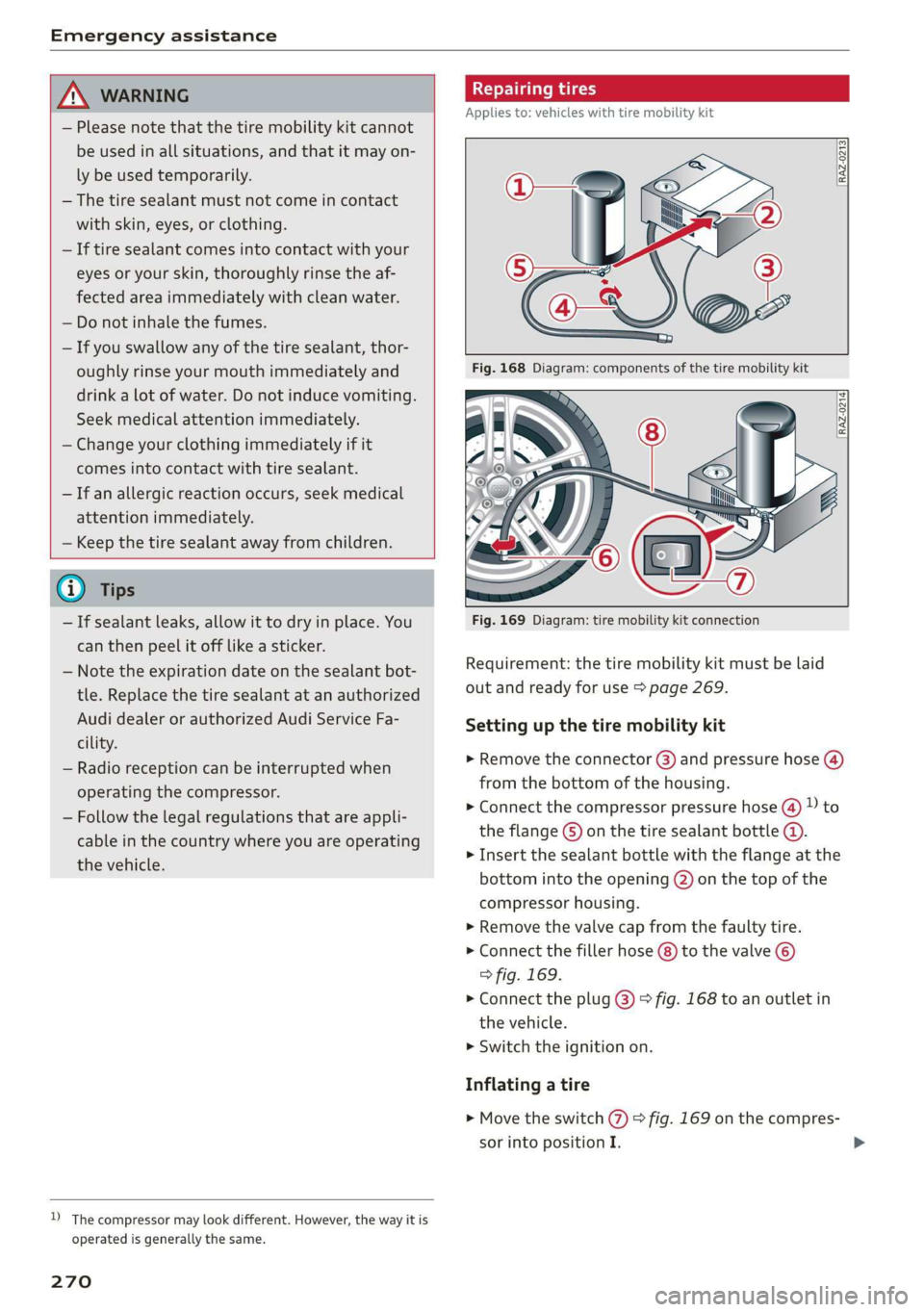
Fig. 169 Diagram: tire mobility kit connection
Requirement: the tire mobility kit must be laid
out and ready for use > page 269.
Setting up the tire mobility kit
> Remove the connector (3) and pressure hose (4)
from the bottom of the housing.
> Connect the compressor pressure hose @ D to
the flange © on the tire sealant bottle ©.
> Insert the sealant bottle with the flange at the
bottom into the opening @) on the top of the
compressor housing.
> Remove the valve cap from the faulty tire.
>» Connect the filler hose (8) to the valve ©)
> fig. 169.
> Connect the plug @) © fig. 168 to an outlet in
the vehicle.
> Switch the ignition on.
Inflating a tire
> Move the switch (7) > fig. 169 on the compres-
sor into position I.
Page 273 of 310
4KE012721BB
Emergency assistance
> Inflate the tire to between 29 psi (200 kPA)
and 36 psi (250 kPA) and read the pressure on
the gauge.
> If this tire pressure is not reached, remove the
filler hose. Drive slowly approximately 33 feet
(10 m) forward or in reverse so that the sealant
can be distributed in the tire. Inflate the tire
again > A\.
ZA\ WARNING
— Read and follow the manufacturer's safety
precautions on the compressor and in the in-
structions on the bottle of sealant.
— Ifa tire pressure of 29 psi (200 kPA) cannot
reached after inflating for 6 minutes, then
the tire is too severely damaged. Do not con-
tinue driving.
— If the tire cannot be repaired with the tire
sealant, see an authorized Audi dealer or au-
thorized Audi Service Facility for assistance.
@) Tips
Do not operate the compressor for more than
six minutes continuously, or it can overheat.
Once the compressor has cooled, you can con-
tinue to use it.
CeeTnn eas]
Applies to: vehicles with tire mobility kit
> Affix the sticker that says "max. 50 mph (max.
80 km/h)" that is provided with the tire mobili-
ty kit within the driver's field of vision.
> Stop the vehicle after driving for about 10 mi-
nutes and check the tire pressure.
> If the tire pressure is lower than 19 psi (130
kPA), then the tire is too severely damaged. Do
not continue driving.
Nv WARNING
Pay attention to the following after repairing
the tire:
— Do not drive faster than 50 mph (80 km/h).
— Avoid hard acceleration or braking and driv-
ing fast around curves.
— The vehicle may become more difficult to
control.
— If the tire is too severely damaged, see an
authorized Audi dealer or authorized Audi
Service Facility for assistance.
(@) For the sake of the environment
You can give the used tire sealant bottle to an
authorized Audi dealer or authorized Audi
Service Facility for disposal.
G) Tips
Remember to obtain a new bottle of sealant
from an authorized Audi dealer or authorized
Audi Service Facility after repairing a tire.
Changing a tire
You must complete the preparation before
changing a tire.
> Read and follow the important safety precau-
tions > page 269.
> Set the parking brake.
> Select the “P” position.
> When towing a trailer: disconnect the trailer
from your vehicle.
> Lay out the vehicle tool kit > page 269 and the
spare tire > page 275.
> Applies to: vehicles with air suspension: Select
on the home screen: VEHICLE > Settings &
Service > Air suspension: wheel change.
> Switch the ignition off.
Z\ WARNING
When using the vehicle jack* on a road with a
steep hill or when offroad, you must take ex-
tra precautions to prevent the vehicle from
rolling. Use suitable objects to block the front
and
back of the wheel that is diagonal from
the wheel with the flat tire.
271
Page 275 of 310
4KE012721BB
Emergency assistance
Raising the vehicle
Applies to: vehicles with vehicle jack
RAZ-0258
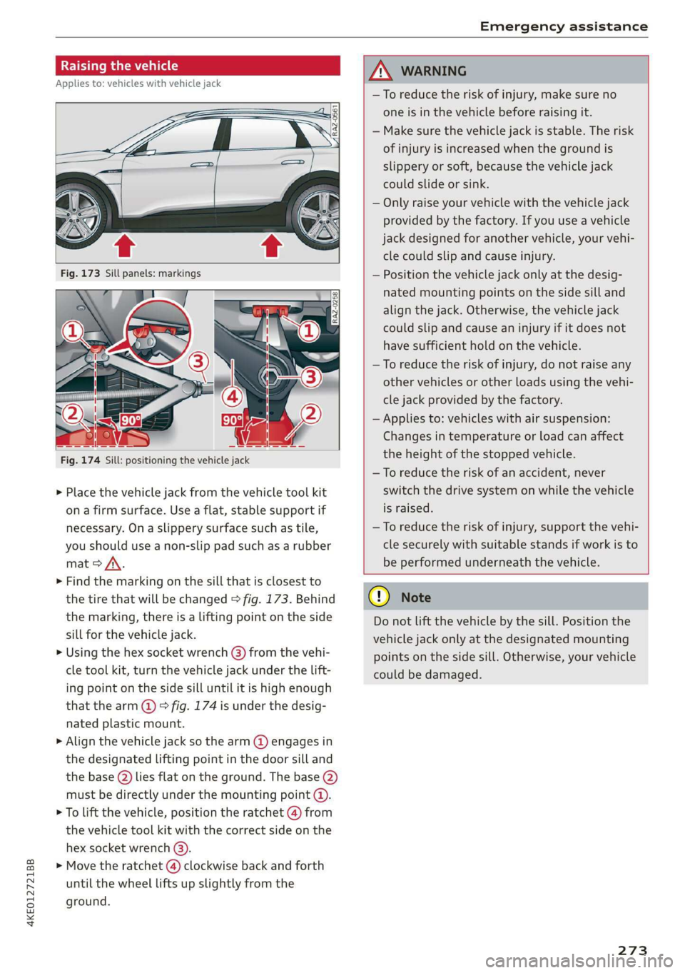
Fig. 174 Sill: positioning the vehicle jack
> Place the vehicle jack from the vehicle tool kit
ona firm surface. Use a flat, stable support if
necessary. On a slippery surface such as tile,
you should use a non-slip pad such as a rubber
mat > /\.
> Find the marking on the sill that is closest to
the tire that will be changed > fig. 173. Behind
the marking, there is a lifting point on the side
sill for the vehicle jack.
» Using the hex socket wrench (3) from the vehi-
cle tool kit, turn the vehicle jack under the lift-
ing point on the side sill until it is high enough
that the arm @ © fig. 174 is under the desig-
nated plastic mount.
> Align the vehicle jack so the arm @ engages in
the designated Lifting point in the door sill and
the base () lies flat on the ground. The base (2)
must be directly under the mounting point (@).
> To lift the vehicle, position the ratchet @ from
the vehicle tool kit with the correct side on the
hex socket wrench (3).
> Move the ratchet (@) clockwise back and forth
until the wheel lifts up slightly from the
ground.
ZX WARNING
—To reduce the risk of injury, make sure no
one is in the vehicle before raising it.
— Make sure the vehicle jack is stable. The risk
of injury is increased when the ground is
slippery or soft, because the vehicle jack
could slide or sink.
— Only raise your vehicle with the vehicle jack
provided by the factory. If you use a vehicle
jack designed for another vehicle, your vehi-
cle could slip and cause injury.
— Position the vehicle jack only at the desig-
nated mounting points on the side sill and
align the jack. Otherwise, the vehicle jack
could slip and cause an injury if it does not
have sufficient hold on the vehicle.
—To reduce the risk of injury, do not raise any
other vehicles or other loads using the vehi-
cle jack provided by the factory.
— Applies to: vehicles with air suspension:
Changes in temperature or load can affect
the height of the stopped vehicle.
—To reduce the risk of an accident, never
switch the drive system on while the vehicle
is raised.
—To reduce the risk of injury, support the vehi-
cle securely with suitable stands if work is to
be performed underneath the vehicle.
@) Note
Do not lift the vehicle by the sill. Position the
vehicle jack only at the designated mounting
points on the side sill. Otherwise, your vehicle
could be damaged.
273,
Page 276 of 310

Emergency assistance
Removing and installing a wheel
@ Rg tT
“% © oO
B8K-1477
Fig. 176 Wheel: alignment pin in the top hole
Removing a wheel
>» Remove the top wheel bolt completely using
the hex socket in the screwdriver handle from
the vehicle tool kit > fig. 175 and place it ona
clean surface.
> Then install the alignment pin from the vehicle
tool kit in the empty wheel bolt hole by hand
> fig. 176.
> Remove the rest of the wheel bolts.
>» Remove the wheel >(). The alignment pin re-
mains in the hole while doing this.
Installing a wheel
Read the directions on > page 274 when instal-
ling unidirectional tires.
> Slide the wheel on over the alignment pin >@.
> Install the wheel bolts and tighten them gently
using the hex socket.
» Remove the alignment pin and tighten the re-
maining wheel bolt.
> Carefully lower the vehicle using the vehicle
jack*.
> Tighten the wheel bolts in a diagonal pattern
using the wheel wrench.
274
The wheel bolts must be clean and loosen and
tighten easily. Check the contact surfaces for the
wheel and hub. Contaminants on these surfaces
must be removed before installing the wheel.
ZA\ WARNING
— Read and follow the important information
and notes under > page 250.
— Never use the hex socket in the screwdriver
handle to tighten the wheel bolts. Using the
hex socket will not achieve the required
tightening torque, which increases the risk
of an accident.
©) Note
When removing or installing the wheel, the
rim
could hit the brake rotor and damage the
rotor. Work carefully and have a second per-
son help you.
Unidirectional tires
A unidirectional tire profile is identified by arrows
on the tire sidewall that point in the running di-
rection. You must always maintain the specified
running direction. This is necessary to ensure the
tire's optimal performance in regard to adhesion,
running noise, and friction, and to reduce the risk
of
hydroplaning.
To benefit fully from the advantages of the uni-
directional tire design, you should replace faulty
tires as soon as possible and restore the correct
running direction on all of the tires.
> Reinstall the caps on the wheel bolts if necessa-
ry.
> Store the vehicle tool kit in its designated
place.
> If the removed wheel does not fit in the spare
wheel well, store it securely in the luggage
compartment > page 77.
> Check the tire pressure on the installed wheel
as soon as possible.
> Correct the tire pressure and store it in the MMI
=> page 262.
Page 277 of 310
4KE012721BB
Emergency assistance
> The wheel bolt tightening specification must be
120 ft lbs (160 Nm). Have it checked as soon as
possible with a torque wrench. Drive carefully
until then.
> Have the faulty wheel replaced as quickly as
possible.
Collapsible spare tire
Applies to: vehicles with collapsible spare tire
The collapsible spare tire is intended for short-
term use only. Have the damaged tire checked
and replaced if necessary by an authorized Audi
dealer or authorized Audi Service Facility as soon
as possible.
There are some restrictions on the use of the col-
lapsible spare tire. The collapsible spare tire has
been designed specifically for your type of vehi-
cle. Do not replace it with the collapsible spare
tire from another type of vehicle.
The collapsible spare tire is located in the lug-
gage compartment under the cargo floor cover.
Requirement: the vehicle tool kit > page 269 and
the compressor must be laid out.
Removing
> Lift the cargo floor using the handle.
> Turn the handwheel counter-clockwise and re-
move it.
> Remove the cover.
> Remove the collapsible spare tire.
You must inflate the collapsible spare tire before-
hand in order to use it.
Inflating
> Remove the valve cap from the collapsible
spare tire.
> Tighten the compressor hose on the collapsible
spare tire valve.
> Connect the compressor hose to a vehicle sock-
et and switch it on.
> Let the compressor run until the specified value
on the tire pressure sticker is reached
> page 253, fig. 165>©.
> Screw the valve cap back onto the valve.
Returning to storage
> Remove the valve cap to drain the air.
» Wait several hours before placing the collapsi-
ble spare tire in the spare wheel well. Only then
will it fold down completely so that you can
store it securely.
> Then screw the valve cap back onto the valve.
> Secure the collapsible spare tire with the cover
and the handwheel.
> Fold the cargo floor cover back into place.
Snow chains
Using snow chains on the collapsible spare tire is
not permitted for technical reasons.
If you have to drive with snow chains and a rear
tire fails, mount the collapsible spare tire in place
of a front tire. Install the snow chains on the
front tire that you removed, and install that in
place of the rear tire that failed.
ZA\ WARNING
— Only use the collapsible spare tire in emer-
gencies and drive very carefully, especially if
it is more than six years old.
— The compressor and the hose can become
very hot during operation which increases
the risk of burn injuries.
— After installing a collapsible spare tire, the
tire pressure must be checked as quickly as
possible to reduce the risk of an accident.
— Do not drive faster than 50 mph (80 km/h)
with the collapsible spare tire. Driving faster
than that increases the risk of an accident.
—To reduce the risk of an accident, avoid hard
acceleration or braking and driving fast
around curves with the collapsible spare
tire.
— Never drive using more than one collapsible
spare tire, because this increases the risk of
an accident.
— Normal tires or winter tires must not be
mounted on the collapsible spare tire rim.
@) Note
The compressor must be switched off after six
minutes at the most to reduce the risk of
275
>
Page 278 of 310
Emergency assistance
overheating. Let the compressor cool down
for several minutes before using it again.
@) Tips
The ESC must not be limited or switched off
when driving with the collapsible spare tire
=> page 102.
Jump starting
The vehicle cannot be operated when the 12 Volt
vehicle battery is drained. Your vehicle must not
be jump started in this case. Contact an author-
ized Audi dealer or authorized Audi Service Facili-
ty.
@) Note
The vehicle battery must not be bridged using
conventional jump start methods.
— You may neither give nor receive a jump
start. Otherwise, the electronic systems in
the vehicle may be severely damaged.
—The jump start pins in the motor compart-
ment are designed specifically for qualified
technicians.
Towing
ee eeue lela)
You should only perform the steps that follow if
you have the necessary tools and technical ex-
pertise.
Towing requires a certain amount of practice. Au-
di recommends contacting a towing company to
have the vehicle transported.
You should only have your vehicle towed by an-
other vehicle when disabled in exceptional cir-
cumstances. Inexperienced drivers should not
tow.
Notes on towing
— The maximum permitted towing speed is 30
mph (50 km/h).
— The maximum permitted towing distance is 30
miles (50 km).
276
Additional information on towing with a tow
truck
The vehicle may only be towed with the front axle
raised. Do not wrap any chains or cables around
the brake lines.
Tow bar and towing cable
The vehicle can be towed with a tow bar or tow-
ing cable. Both drivers should be familiar with
the special considerations when towing, especial-
ly when using a towing cable.
Always make sure the traction force does not ex-
ceed the permitted level and there are no shock
loading conditions. There is always the risk of the
coupling becoming overloaded when driving off-
road.
For the most safety and security, drive with a tow
bar. You should use a towing cable only if a tow
bar is not available. Use a towing cable made of
synthetic elastic cable similar elastic material.
ZA WARNING
— Towing highly increases the risk of an acci-
dent, for example from colliding with the
towing vehicle.
—To reduce the risk of an accident, do not al-
low anyone to remain inside the vehicle
when it is being transported by a tow truck
or a special transporter.
@) Note
—Ifthe |_E| indicator light turns on, there is a
fault in the cooling circuit. The vehicle must
not be towed. The drive system can be se-
verely damaged.
— If normal towing is not possible, for exam-
ple if the transmission is faulty or if the
towing distance is greater than 30 miles
(50 km), then transport the vehicle on a
special carrier.
— If the vehicle is towed by a tow truck at the
axle that is not permitted, this can cause se-
vere damage to the transmission.
— Towing must not be used to charge the
high-voltage battery (recuperation), be-
cause this could result in major damages to
the tow vehicle or the vehicle being towed. >
Page 284 of 310
Fuses and bulbs
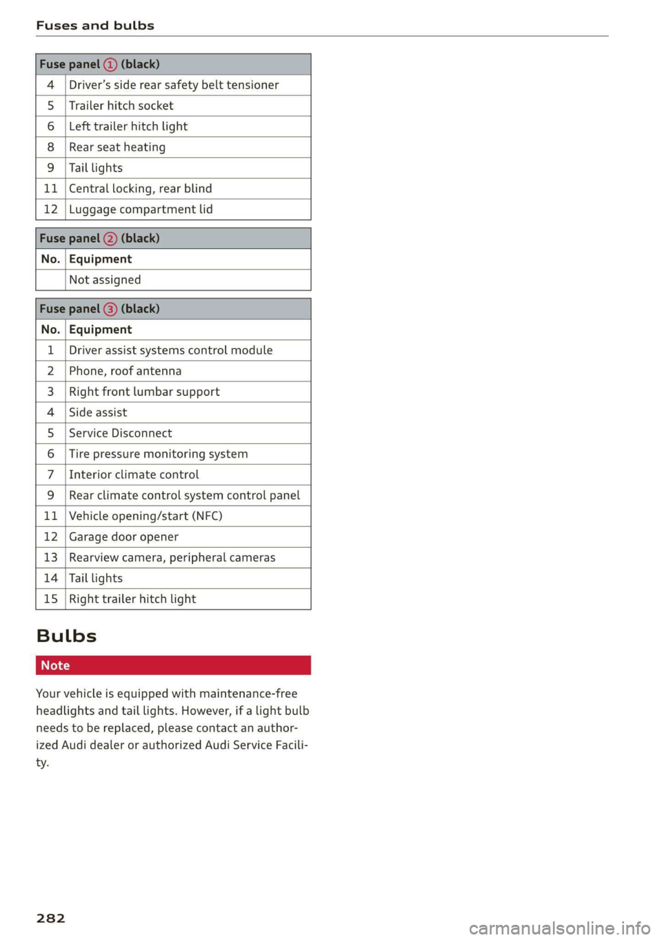
Driver’s side rear safety belt tensioner
4
5 |Trailer hitch socket
6 |Left trailer hitch light
8
9
Rear seat heating
Tail lights
11 | Central locking, rear blind
12 |Luggage compartment lid
No. | Equipment
Not assigned
2), og . | Equipment
Driver assist systems control module
Phone, roof antenna
Right front lumbar support
Side assist
Service Disconnect
Tire pressure monitoring system
Interior climate control
WOIN
A|M|)A)/WIN]
PR
Rear climate control system control panel
Vehicle opening/start (NFC)
Hb BR
bh N Garage door opener
pa Ww Rearview camera, peripheral cameras
Tail lights
Right trailer hitch light
be KR
Hb uw
Bulbs
Your vehicle is equipped with maintenance-free
headlights and tail lights. However, if a light bulb
needs to be replaced, please contact an author-
ized Audi dealer or authorized Audi Service Facili-
ty.
282
Page 294 of 310
Technical data
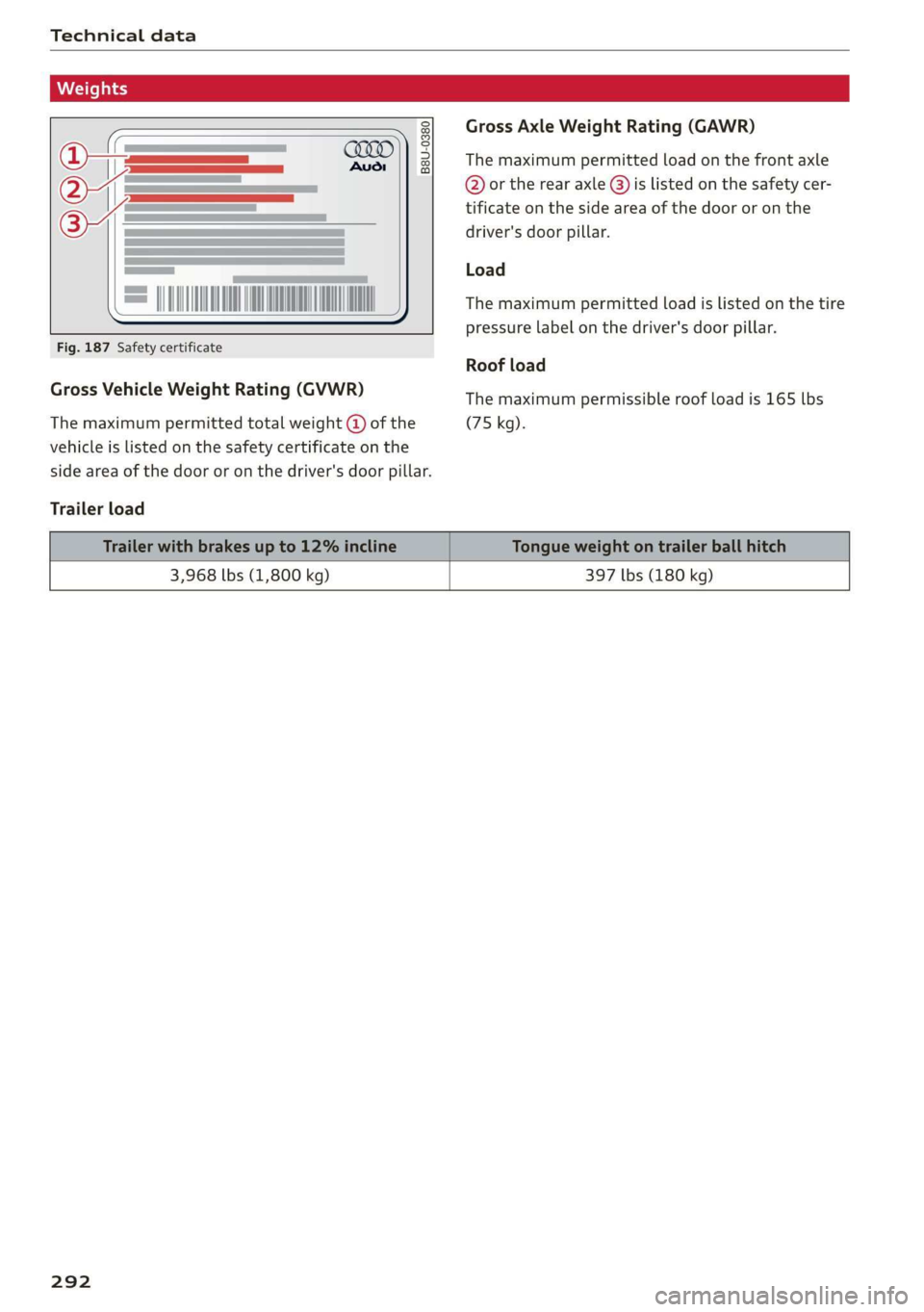
Gross Axle Weight Rating (GAWR)
B8U-0380 The maximum permitted load on the front axle
@ or the rear axle @) is listed on the safety cer-
tificate on the side area of the door or on the
driver's door pillar.
Load
The maximum permitted load is listed on the tire
pressure label on the driver's door pillar.
Fig. 187 Safety certificate
Roof load
Gross Vehicle Weight Rating (GVWR) The maximum permissible roof load is 165 lbs
The maximum permitted total weight @ of the (75 kg).
vehicle is listed on the safety certificate on the
side area of the door or on the driver's door pillar.
Trailer load
3,968 lbs (1,800 kg) 397 lbs (180 kg)
292
Page 296 of 310
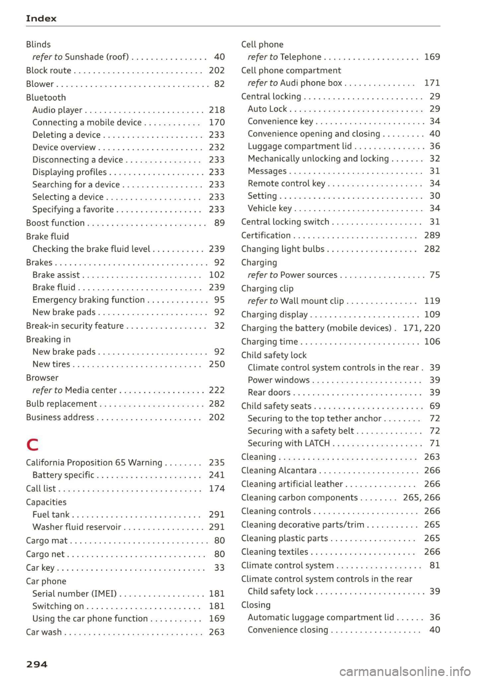
Index
Blinds
refer to Sunshade (roof) ............00-5 40
Block
route................ 00 cece eee 202
BLOWER. « sees su comers a enmeane wa nents a = swine = 82
Bluetooth
Audio player........... 0.00 e eee eee 218
Connecting a mobile device............ 170
Deleting
ardevice wii s 2 isnsins ov sucrose « sence 233
Device overVieW...... 6c eee ee eee eee 232
Disconnecting a device................ 233
Displaying profiles.................... 233
Searching fora device...............-. 233
Selecting adevice.............2eeeeee 233
Specifying a favorite.................. 233
BOOStTUNCTION owas x cee 2 sneer 2 eo ces ¢ 89
Brake fluid
Checking the brake fluid level........... 239
Brak Sicnes 2 x sree: vo cmv ow orien ow soe © o ooEKS 92
Brakerassist. scsmrs « acess» oi soz 4 0 omens « 102
Brake fluid. .................0..0000. 239
Emergency braking function............. 95
New brake pads..............---00000- 92
Break-in security feature................. 32
Breaking in
New brake pads............0.20200000- 92
NGW TIRES: « « noms 2 s saros & 9 cate gs eam a 250
Browser
refer to Mediacenter................4. 222
Bulb replacement.............--22+-05- 282
Business: address). «i ijei as jana a scan a va 202
Cc
California Proposition 65 Warning........ 235
Batteryspecific... =. eccs s sive s ween as: 241
GALLLISt « wea ¢ 2 aeee xs meee oe eee s Bee ee 174
Capacities
Fuebtanike, « secs 2 a oasan oo ssamon o wana oo ove 291
Washer fluid reservoir................- 291
Cangowmatc © « conse ws aussins 6 0 secs a a amass We ae 80
Cargoinets: « s soma 2s memew + wauim a 3 mam 6 @ oarae 80
Car key « s eeu oy ews y oeE 6 2 ween 6 Ewes 33
Car phone
Serialinumber(IMED) « wsscsce ao soteane ao sanaia 181
Switching on... ....... eee eee eee 181
Using the car phone function........... 169
Car WASH: = sass 5 x eee 5 feats sb eG EE 263
294
Cell phone
refer to Telephone...........-0e eee eae 169
Cell phone compartment
refer to Audi phone box............... 171
Central
locking ...... 0. cece eee eee eee 29
AUTO LOCK: » geese + sunems 2 seene & 3 donee & = Be 29
Convenience key « sscsu © cvenesie © erase wo vnscem 34
Convenience opening and closing......... 40
Luggage compartment lid............... 36
Mechanically unlocking and locking....... 32
Messages... 1.6... ce eee cece eee eee 31
Remote control keys: ss esas ss eves os ees 34
SettN's 6 e wanes a a saws «wo ones vo meen + 8 o8TH 30
Vehicle key... 6... ccc ee eee eee eee 34
Central locking switch.............000005 31
Centificat onto» a sess + x aneans ao somes o 6 mmm 289
Changing lightibulbs'. « ccs ss sew s 6 sesso 282
Charging
refer to Power sourceS............00 000s 75
Charging clip
refer to Wall mount clip............... 119
Charging display................---0000- 109
Charging the battery (mobile devices). 171, 220
Charging times. « sass. se savin s 2 wees © 2 sree 106
Child safety lock
Climate control system controls in the rear. 39
POWER WINK OWS inc ¢ & cme 5 ores 5 v eee 39
Rear doorsten « swe so mim 2 women n= ame wD 39
Child
safety seats........ 0... ce eee ee eee 69
Securing to the top tether anchor........ 72
Securing with a safety belt.............. 72
Securing with LATCH. ss sses ss eee se eee 71
Gl@aNiNG ¢ sere « s ewes 5 o eee se eee ce ees 263
Cleaning Alcantara.............-..0000. 266
Cleaning artificial leather............... 266
Cleaning carbon components........ 265, 266
Cleaning controls..............00 eee eee 266
Cleaning decorative parts/trim........... 265
Cleaning plastic parts.................. 265
Cleaning textiles: s ws + wees v ween oe eee 266
Climate control system ..............004. 81
Climate control system controls in the rear
Child safetylotk.o icvc os soci © sean © wows 39
Closing
Automatic luggage compartment lid...... 36
Convenience closing................045 40