key AUDI E-TRON 2021 Owner's Manual
[x] Cancel search | Manufacturer: AUDI, Model Year: 2021, Model line: E-TRON, Model: AUDI E-TRON 2021Pages: 308, PDF Size: 83.91 MB
Page 66 of 308
Sitting correctly and safely
> Insert a suitable object, such as the extended
vehicle key or mechanical key, into the release
point @ on the inside or outside of the base.
> Press the button @) and pull the head restraint
out of the backrest > /\ in General informa-
tion on page 63.
Installing the headrests
Applies to: vehicles with removable head restraints
> Fold the backrest forward slightly > page 82.
>» Slide the posts on the head restraint down into
the guides until the posts click into place.
> Press the button (2) and slide the head restraint
all the way down. It should not be possible to
remove the head restraint from the backrest
without pressing the button.
Safety belts
Each seat is equipped with a three-point safety
belt. Safety belts that are worn correctly are the
most effective way to reduce the risk of serious or
fatal injuries in a collision. Therefore, wear your
safety belt correctly and make sure that all vehi-
cle passengers are also wearing their safety belts
correctly when the vehicle is moving.
Even though your vehicle is equipped with an air-
bag system, every vehicle passenger must still al-
ways wear the appropriate safety belt. In addi-
tion to their normal protective function, safety
belts also hold vehicle occupants in the correct
seating position in the event of a collision so that
the airbags can deploy correctly and provide addi-
tional protection. Safety belts provide protection
during collisions when the airbags do not deploy
or if they have already deployed.
Z\ WARNING
The risk of serious or fatal injury increases if
the safety belt is not fastened, if it is worn in-
correctly, or if it is damaged.
—All vehicle occupants, including the driver,
must fasten their safety belts correctly be-
fore every trip and must always keep their
safety belts fastened during the trip, regard-
less of whether the seat is equipped with an
64
airbag or not. This also applies to children
that are seated in a child safety seat that is
appropriate for their weight and age and
that is secured with a safety belt.
In the event of a collision, vehicle occupants
that are not wearing safety belts could be
propelled through the vehicle interior and
collide with vehicle components, such as the
steering wheel, instrument panel, wind-
shield, or doors. In some situations, vehicle
occupants could also be ejected from the ve-
hicle. Vehicle occupants in the rear seats
who do not wear safety belts not only en-
danger themselves, but also other people in
the vehicle.
Only one person may be fastened with a
safety belt at a time. Never secure more
than one person, including children, with a
single safety belt.
Never allow children or infants to ride on an-
other person's lap and be belted into the
safety belt with them.
Insert the belt buckle only in the belt latch
belonging to the corresponding seat, so that
the protective function is not impaired.
To ensure the maximum protective function
of the safety belts, all vehicle passengers
must sit in the correct seating position
=> page 59.
Check the condition of your vehicle’s safety
belts regularly > page 262. If you find dam-
age to the belt webbing, the belt connec-
tions, the retractor, or the buckle, have the
damaged safety belt replaced by an author-
ized Audi dealer or authorized Audi Service
Facility.
The safety belts must not be removed or
modified in any way. Do not attempt to re-
pair the safety belts yourself.
Safety belts that are strained during an acci-
dent must be replaced by an authorized
Audi dealer or authorized Audi Service Facili-
ty.
Page 80 of 308
Storage and convenience
Storage and convenience
Power sources
When the ignition is switched on, you may be
able to use multiple power sources for external
devices, depending on the vehicle equipment.
12 volt sockets
You can connect electrical accessories to the 12
volt sockets. The power usage from the sockets
must not exceed a total of 120 watts. Do not
connect multiple devices to the sockets in the ve-
hicle at the same time.
The 12 volt sockets are labeled with the 12V
symbol. They are located in the front center con-
sole, in the rear, and on the side trim panel in the
luggage compartment.
USB ports
Applies to: vehicles with USB port
You can charge mobile devices using the USB
ports. The USB ports are labeled with the «> or
[4 symbol or CHARGE ONLY.
| Z\ WARNING
— To reduce the risk of fatal injury, store all
connected devices securely when driving so
that they do not move around inside the ve-
hicle when braking or in the event of an acci-
dent.
— Incorrect usage can lead to serious injuries
or burns. To reduce the risk of injuries, never
leave children unattended in the vehicle
with the vehicle key.
@) Note
— Read the operating manuals for the con-
nected devices.
—To reduce the risk of damage to the vehicle
electrical system, never attempt to charge
the vehicle battery by connecting accesso-
ries that provide power to the power sour-
ces.
— Do not connect any device whose network
class (voltage) does not match the network
class designed for the socket.
78
— Disconnect the connectors from the power
sources carefully to reduce the risk of dam-
aging them.
@ Tips
Do not connect any other devices to the sock-
ets when using the compressor* provided by
the factory > page 267. The power consump-
tion in the sockets may be temporarily ex-
ceeded when using the compressor*.
Cup holders
Applies to: vehicles with cup holders
4
2
RAZ-1177,
Fig. 66 Rear center armrest”: cup holders
Cup holders in the front center console
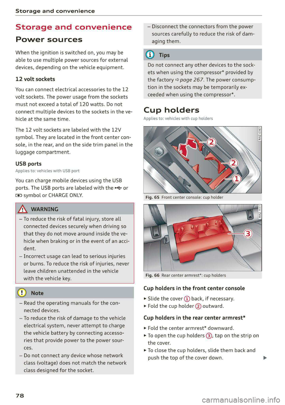
> Slide the cover (4) back, if necessary.
> Fold the cup holder @) outward.
Cup holders in the rear center armrest*
> Fold the center armrest* downward.
> To open the cup holders (@), tap on the strip on
the cover.
> To close the cup holders, slide them back and
push the top of the cover down.
Page 92 of 308
Driving
Driving
Starting the vehicle
pyre d | ola eda)
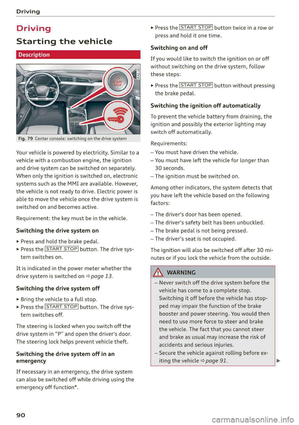
Fig. 79 Center console: switching on the drive system
Your vehicle is powered by electricity. Similar to a
vehicle with a combustion engine, the ignition
and drive system can be switched on separately.
When only the ignition is switched on, electronic
systems such as the MMI are available. However,
the vehicle is not ready to drive. Electric power is
able to move the vehicle once the drive system is
switched on and becomes active.
Requirement: the key must be in the vehicle.
Switching the drive system on
> Press and hold the brake pedal.
> Press the [START STOP] button. The drive sys-
tem switches on.
It is indicated in the power meter whether the
drive system is switched on > page 13.
Switching the drive system off
> Bring the vehicle to a full stop.
> Press the [START STOP] button. The drive sys-
tem switches off.
The steering is locked when you switch off the
drive
system in “P” and open the driver's door.
The steering lock helps prevent vehicle theft.
Switching the drive system off in an
emergency
If necessary in an emergency, the drive system
can also be switched off while driving using the
emergency off function*.
90
> Press the [START STOP] button twice in a row or
press and hold it one time.
Switching on and off
If you would like to switch the ignition on or off
without switching on the drive system, follow
these steps:
> Press the [START STOP] button without pressing
the brake pedal.
Switching the ignition off automatically
To prevent the vehicle battery from draining, the
ignition and possibly the exterior lighting may
switch off automatically.
Requirements:
— You must have driven the vehicle.
— You must have left the vehicle for longer than
30 seconds.
— The ignition must be switched on.
Among other indicators, the system detects that
you have left the vehicle based on the following
factors:
— The driver's door has been opened.
— The driver's safety belt has been unbuckled.
— The brake pedal is not being pressed.
— The driver's seat is not occupied.
The ignition will also be switched off after 30 mi-
nutes or if you lock the vehicle from the outside.
ZA WARNING
— Never switch off the drive system before the
vehicle has come to a complete stop.
Switching it off before the vehicle has stop-
ped may impair the function of the brake
booster and power steering. You would then
need to use more force to steer and brake
the vehicle. The fact that you cannot steer
and brake as usual may increase the risk of
accidents and serious injuries.
— Secure the vehicle against rolling before ex-
iting the vehicle > page 91. >
Page 93 of 308
4KE012721BF
Driving
@) Tips
— Brief noises are normal when starting and
stopping the vehicle and are no cause for
concern.
— It may not be possible to start the vehicle in
extremely low temperatures.
— The drive power depends on the tempera-
ture and the charge level of the high-volt-
age battery.
Messages
E Engine start system: malfunction! Please
contact Service
Do not switch the ignition off because you may
not be able to switch it on again. Drive to an au-
thorized Audi dealer or authorized Audi Service
Facility immediately to have the malfunction cor-
rected.
E Engine start system: malfunction! Please
contact Service
There is a malfunction in the engine start system.
Drive immediately to an authorized Audi dealer
or authorized Audi Service Facility to have the
malfunction repaired.
B Remote control key: key not detected. Is the
key
still in the vehicle?
The vehicle key was removed from the vehicle
while the drive system was active. If the vehicle
key is no longer in the vehicle, you can no longer
switch on the ignition or the drive system after
switching off the drive system. You also cannot
lock the vehicle from the outside.
Remote control key: hold back of key
against the designated area. See owner's man-
ual
The battery in the vehicle key may be drained or
there may be a malfunction. To start the vehicle,
you must also hold the vehicle key against the lo-
cation shown ?) > page 90, fig. 79.
If the malfunction remains, drive immediately to
an authorized Audi dealer or authorized Audi
Service Facility to have the malfunction correct-
ed.
When driving
Starting to drive, stopping, and parking
Starting from a stop
> Press and hold the brake pedal.
> Switch on the drive system.
> Select a gear.
> Release the parking brake.
> Release the brake pedal.
> Press the accelerator pedal to accelerate.
Always make sure that the vehicle does not
“creep” when starting to drive and maneuvering.
If you take your foot off the brake pedal, the ve-
hicle will not be set into motion by the drive sys-
tem.
Securing the vehicle against rolling
Secure your vehicle to prevent it from rolling be-
fore exiting the vehicle.
>» Set the parking brake.
> Select the “P” selector lever position.
> If parking on a steep road, turn the steering
wheel so that your vehicle will roll against the
curb in case it should start to move.
If one of these measures is not possible, for ex-
ample because there is no vehicle power, you
must secure your vehicle against rolling using ad-
ditional measures.
> Only park the vehicle on a level surface.
> Use suitable objects to block the front and rear
wheels.
Set the parking brake before selecting the “P” se-
lector lever position. This prevents too much
stress from being placed on the locking mecha-
nism when parking on a steep surface.
ZA WARNING
— Always set the parking brake when leaving
your vehicle, even if for a short period of
time. If the parking brake is not set, the ve-
hicle could roll away, increasing the risk of
an accident.
— Do not leave your vehicle unattended while
the drive system is active, because this in-
creases the risk of an accident. >
91
Page 94 of 308
Driving
— If the parking brake is set, it can release au-
tomatically when the accelerator pedal is
pressed. To reduce the risk of an accident,
do not inadvertently press the accelerator
pedal and always shift into “P” when the ve-
hicle is stopped.
— If you leave the vehicle, switch the ignition
off and take the key with you. This is espe-
cially important when leaving persons or an-
imals in the vehicle. Otherwise, the vehicle
could start unintentionally, the parking
brake could release, or electronic equipment
could activate, which increases the risk of an
accident.
— No persons or animals should be left in a
locked vehicle. Locked doors make it more
difficult for emergency workers to enter the
vehicle, which puts lives at risk.
— If you do not begin driving immediately af-
ter releasing the brake pedal, your vehicle
may begin to roll backward. Press the brake
pedal or set the parking brake immediately.
@) Note
If you have to stop on an incline, always press
the brake pedal to hold the vehicle in place to
reduce the risk of the vehicle rolling back-
ward. Do not try to hold the vehicle in place
by pressing and holding the accelerator pedal.
The transmission can overheat, which increas-
es the risk of damage.
Hill hold assist
If you take your foot off of the brake pedal when
driving on hills, the braking force will be held for
several seconds. At that time, you can start driv-
ing without the vehicle rolling backward.
Requirement: the driver's door must be closed,
the drive system must be active, and the vehicle
must be traveling uphill.
> To activate hill hold assist, press and hold the
brake pedal for several seconds while the vehi-
cle is stationary.
Use the hold assist > page 99 when the braking
force should be applied for more than several
seconds.
92
ZA\ WARNING
— If you do not begin driving immediately af-
ter releasing the brake pedal, your vehicle
may begin to roll backward. Press the brake
pedal
or set the parking brake immediately.
— The hill hold assist cannot hold the vehicle
on inclines in every scenario (for example,
on slippery or icy ground).
Gears and driving programs
RAZ-0570
P-|
D,
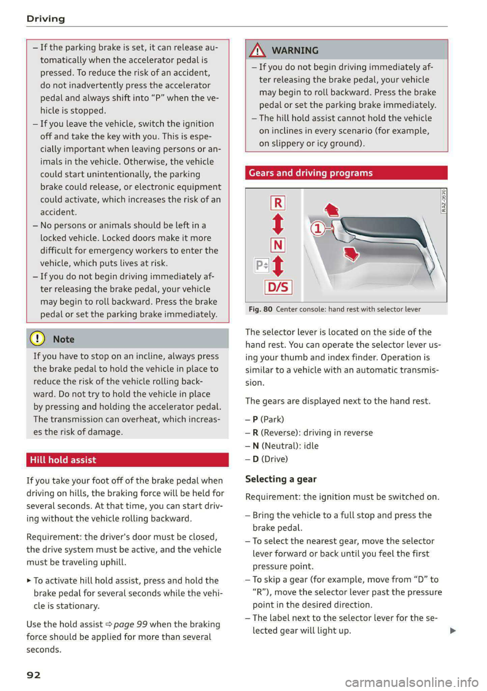
Fig. 80 Center console: hand rest with selector lever
t
The selector Lever is located on the side of the
hand rest. You can operate the selector lever us-
ing your thumb and index finder. Operation is
similar to a vehicle with an automatic transmis-
sion.
The gears are displayed next to the hand rest.
— P (Park)
—R (Reverse): driving in reverse
—N (Neutral): idle
—D (Drive)
Selecting a gear
Requirement: the ignition must be switched on.
— Bring the vehicle to a full stop and press the
brake pedal.
—To select the nearest gear, move the selector
lever forward or back until you feel the first
pressure point.
—To skip a gear (for example, move from “D” to
“R”), move the selector lever past the pressure
point in the desired direction.
— The label next to the selector lever for the se-
lected gear will light up.
Page 104 of 308
Driving dynamic
Driving dynamic
Audi drive select
Introduction
Applies to: vehicles with Audi drive select
Drive select makes it possible to experience dif-
ferent types of vehicle characteristics in one vehi-
cle. With different driving modes, the driver can
switch the setting, for example from sporty to
comfortable. This allows you to adjust the set-
tings to your personal preferences. This makes it
possible to combine settings such as a sporty
drivetrain setting with comfortable steering.
Selecting an Audi drive select mode
Applies to: vehicles with Audi drive select
The sie button is located above the selector lever
in the center console.
> Press the left or right arrow key until the de-
sired mode appears in the MMI. Or:
» Applies to MMI: Select on the home screen: VE-
HICLE > Audi drive select.
You can change the driving mode when the vehi-
cle is stationary or while driving. If traffic per-
mits, briefly remove your foot from the accelera-
tor pedal after changing modes so that the mode
you have selected will be activated for the drive
system.
The following modes may be available depending
on the equipment:
offroad - Provides assistance when driving off-
road. The vehicle will be raised to the second-
highest level using the air suspension®. The ESC
will be restricted and the hill descent assist* will
be activated. The vehicle will exit this mode after
the ignition is switched off.
allroad - Provides balanced vehicle handling. The
vehicle will be raised to the second-highest level
using the air suspension*.
efficiency - The vehicle switches to a fuel-effi-
cient vehicle setup and supports the driver with
fuel economy messages. The “E” driving program
is selected.
102
comfort - Provides a comfort-oriented vehicle
setup and is suited for long drives on highways.
auto - Provides an overall comfortable yet dy-
namic driving feel and is suited for everyday use.
dynamic - Gives the driver a sporty driving feel
and is suited to a sporty driving style. The “S”
driving program is selected.
Individual - Provides the option for personalized
vehicle settings. Press [7 to configure the mode
= page 102, Individual settings.
(i) Tips
When the ignition is being switched on, indi-
vidual systems, such as the drive system, will
be reset to a balanced setting. Select the cur-
rent mode again to attain its full configura-
tion.
Individual settings
Applies to: vehicles with Audi drive select
The equipment in your vehicle will determine
which settings you can adjust.
Drive
The drive system will react to accelerator pedal
moves more quickly or in a more balanced man-
ner.
Steering
The power steering will adapt. Light steering is
suitable for long trips on highways or smooth
driving around curves, for example.
Suspension
The suspension adjusts to be tighter or more
comfort-oriented when it comes to compensat-
ing for uneven spots on the road.
The vehicle ground clearance is adjusted by the
air suspension* based on the setting.
Page 114 of 308

High-voltage system
in direct sunlight for long periods of time. If
the control unit is overheated, the charging
process is automatically paused until the
temperature has lowered back within the
normal range.
Fig. 83 Left front side of the vehicle: opening the high-
voltage charging port door
Fig. 84 Charging unit: charging port and LED
Connecting the charging cable
If you charge your vehicle at a charging station,
the following sequence of steps may vary. Follow
the manufacturer guidelines and operating in-
structions for the charging station.
Requirement: the “P” gear must be selected, the
parking brake must be set, and drive ready mode
must have ended.
—If necessary, remove the charging cable from
the vehicle > page 119, Transport.
— Remove the cap from the charging cable if nec-
essary.
— First connect the charging cable to the power
supply, or remove it from the charging station.
— Unwind the charging cable completely.
— Unlock the charging port door by unlocking the
vehicle. In vehicles with a convenience key*, the
112
charging port door will be automatically un-
locked when the convenience key is near the
charger.
— Press the center of the button @ to open the
charging port door on the driver's side or front
passenger's side*.
— If you would like to use quick charging at public
direct current (DC) charging stations, open the
charging port cover (4).
— Plug the charging connector into the vehicle
charging port.
— Check if the charging option shown @) (immedi-
ate charging/timer charging) is the one you
would like to use for charging.
Starting to charge automatically (immediate
charging)
If charging is not delayed with a timer, the charg-
ing process will begin immediately. If necessary,
the charging station may need to be activated.
Follow the manufacturer guidelines and operat-
ing instructions for the charging station.
You can also adjust the charging process to your
preferences > page 115, Setting the charging
target, > page 116, Setting the timer,
= page 116, Advanced charging settings.
Timer charging
With timer charging, the charging process starts
and ends based on a timer that is set beforehand.
—To charge by timer, switch on the timer and
timer charging before exiting the vehicle
=> page 116.
If the charging connector is disconnected and re-
connected while timer charging is switched on,
immediate charging will activate automatically.
To continue charging by timer, timer charging
must be switched on again.
While charging
The charging display on the charging unit @) will
pulse green while charging. It will pulse is in
the instrument cluster. A label on the charging
unit @) informs you about the various displays
=> page 114.
The charging connector is locked while charging
and cannot be removed.
Page 115 of 308

4KE012721BF
High-voltage system
Depending on the selected view > page 12, the
following information about the charging process
is displayed in the instrument cluster:
— Gv: range
—&: remaining charging time until the charging
process is complete
— 2): current battery charge level
—Q: date and time of when the charging process
was completed
—&: charging speed (additional range per hour)
—4: charging power (depends on the selected
power source)
To access the charging process information at a
later time, select in the instrument cluster: Vehi-
cle functions tab > EE] button > Charging.
Ending the charging process
You can interrupt the charging process at any
time.
— Unlock the vehicle. In vehicles with a conven-
ience key*, the convenience key only needs to
be near the charging port door.
— Press the center of the button @.
— Remove the charging connector. If the charging
connector is not removed within 30 seconds, it
will automatically relock and the charging proc-
ess may continue.
— After removing the charging connector, the
charging port door will close automatically;
otherwise, press on the center of the button @
to close the charging port door.
— Disconnect the charging cable from the power
supply if necessary or return it securely to the
charging station.
— Install the protective caps on the charging ca-
ble again.
—If you are transporting the charging cable in
the vehicle, store it securely > page 119.
If the charging connector cannot be disconnected
from the vehicle, perform the following steps in
the order listed and try again to disconnect the
charging connector:
— Switch the ignition on/off.
— Lock/unlock the vehicle.
— Make sure the auxiliary air conditioning is not
activated > page 87.
If the charging connector still cannot be discon-
nected, you must unlock it manually > page 116.
If you cannot disconnect the charging connector
from the charging station, authenticate yourself
again at the charging station and then try again
to disconnect the charging connector. If you still
cannot disconnect the charging connector from
the charging station, contact the charging sta-
tion operator.
Z\ WARNING
—When closing the charging port door, make
sure the area where the door is closing is
clear to reduce the risk of injury.
— Do not disconnect the charging cable from
the socket or the vehicle charging port while
the vehicle is charging. End the charging
process before removing the charging cable
from the socket in order to reduce the risk of
damaging the connector contacts from
sparks.
— Never drive with the charging port door
open. An open charging port door could hit
other road users, which increases the risk of
injury.
— Ifa charging unit is damaged, the vehicle
must not be charged at the damaged charg-
ing port or at the charging port on the other
side* to reduce the risk of injury.
— If the charging unit is damaged or the
charging port door cannot close or is miss-
ing, drive immediately to an authorized Audi
dealer or authorized Audi Service Facility
and have the malfunction corrected to re-
duce the risk of injury.
@) Note
— If you drive with the charging unit open,
both the charging port door and the elec-
tronics installed behind it could be dam-
aged. Check each time after charging if the
port door is locked before you start driving
the vehicle.
— Applies to: vehicles with charging ports on
the driver and front passenger’s side: Never
attempt to charge the vehicle using both
113
>
Page 127 of 308
4KE012721BF
High-voltage system
— Only change cables in a dry environment.
— The Audi charging system may only be used
as a complete unit consisting of the power
cables, the control unit, and the vehicle ca-
ble. Depending on the country, the total
length of the power cable, control panel and
vehicle cable may be restricted, for example
to 24.6 feet (7.5 m) in the USA. Audi recom-
mends using only cables approved by Audi.
@) Tips
The power cable with the power connector for
industrial sockets and the Audi charging sys-
tem control unit are designed to work togeth-
er. Changing the power cable to another con-
nector type may reduce the available charging
power of the entire system. Limitations on
the ability to transfer power (current capacity)
depending on the phase and the number of
available phases may affect the available
charging power.
Wall mo clip
Applies to: vehicles with wall mount clip
RAZ-0638,
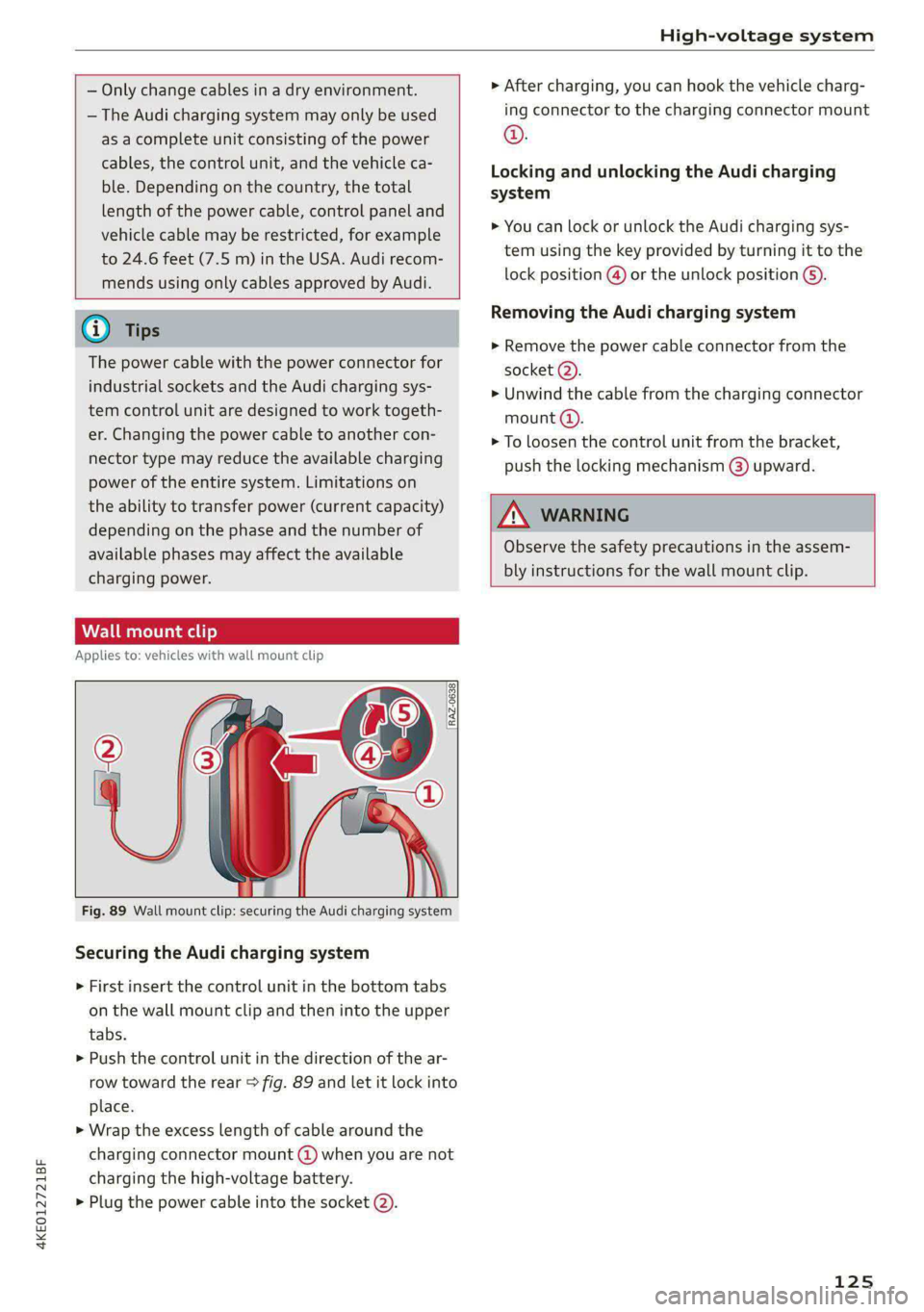
Fig. 89 Wall mount clip: securing the Audi charging system
Securing the Audi charging system
> First insert the control unit in the bottom tabs
on the wall mount clip and then into the upper
tabs.
> Push the control unit in the direction of the ar-
row toward the rear > fig. 89 and let it lock into
place.
> Wrap the excess length of cable around the
charging connector mount @ when you are not
charging the high-voltage battery.
> Plug the power cable into the socket (2).
> After charging, you can hook the vehicle charg-
ing connector to the charging connector mount
©.
Locking and unlocking the Audi charging
system
> You can lock or unlock the Audi charging sys-
tem using the key provided by turning it to the
lock position @) or the unlock position 6).
Removing the Audi charging system
> Remove the power cable connector from the
socket (2).
> Unwind the cable from the charging connector
mount (@).
> To loosen the control unit from the bracket,
push the locking mechanism @) upward.
ZX WARNING
Observe the safety precautions in the assem-
bly instructions for the wall mount clip.
125
Page 191 of 308
4KE012721BF
Audi connect
ZA WARNING
— Always follow the information found in > AA
in General information on page 186.
— Driver messages, text messages, and illumi-
nated warning and indicator lights in the ve-
hicle always take priority over information
from the Audi connect services. The infor-
mation displayed by the Audi connect serv-
ices should not cause you to take safety
risks. This can result in the vehicle breaking
down in traffic and to serious injuries or ac-
cidents.
— Applies to: vehicles with electric drive: Only
perform the Audi connect climate control
functions if your vehicle was shut off cor-
rectly and the ignition is switched off.
— Applies to: vehicles with electric drive: Only
perform charging functions on the high-
voltage battery if the vehicle is shut off cor-
rectly, is connected to a suitable socket ,and
if the ignition is switched off.
@) Tips
— Accessing specific data or controlling func-
tions remotely depends on the charge level
of the vehicle battery. Therefore, these
functions only have limited availability after
switching off the ignition.
— An eSIM card establishes the Internet con-
nection for Audi connect vehicle control
services. The costs for this are included in
the price of Audi connect vehicle control
services. The cell phone network, for exam-
ple, must be available to use these services.
Applies to: vehicles with Audi connect vehicle control
Create a myAudi account by registering in the
myAudi app or at my.audi.com, depending on
your country.
>» Set the key user > page 29.
> Install the myAudi app on your mobile device
and log in with your access information.
@) Tips
Some services require you to enter a 4-digit
PIN that you set up during registration.
Settings
Applies to: vehicles with Wi-Fi hotspot
Requirement: the ignition must be switched on.
> Applies to: MMI: Select on the home screen:
SETTINGS > Connection settings > Wi-Fi
Depending on the country and the vehicle equip-
ment, the following functions may be available:
Wi-Fi
When the function is switched on, the MMI's Wi-
Fi hotspot is active and Wi-Fi devices can be con-
nected to the hotspot.
Wi-Fi hotspot settings
The Wi-Fi connection between the MMI and your
Wi-Fi device is encrypted. You can change the fol-
lowing information if needed.
— Access point (SSID): name of the Wi-Fi hot-
spot.
— Password: an initial password was set at the
factory in the MMI. Audi recommends changing
the initial password. Only use secure passwords
that conform to the general guidelines for se-
cure passwords. For more information, refer to
reputable and current sources on password se-
curity.
Allow data connection through Wi-Fi
When the function is switched on, mobile devices
can use the Internet connection through the Wi-
Fi hotspot. A data plan is needed to do this.
Z\ WARNING
Always follow the information found in > AA
in General information on page 186.
@) Note
Always follow the information found in S@ in
General information on page 186.
189