charger AUDI E-TRON 2021 Owners Manual
[x] Cancel search | Manufacturer: AUDI, Model Year: 2021, Model line: E-TRON, Model: AUDI E-TRON 2021Pages: 308, PDF Size: 83.91 MB
Page 114 of 308

High-voltage system
in direct sunlight for long periods of time. If
the control unit is overheated, the charging
process is automatically paused until the
temperature has lowered back within the
normal range.
Fig. 83 Left front side of the vehicle: opening the high-
voltage charging port door
Fig. 84 Charging unit: charging port and LED
Connecting the charging cable
If you charge your vehicle at a charging station,
the following sequence of steps may vary. Follow
the manufacturer guidelines and operating in-
structions for the charging station.
Requirement: the “P” gear must be selected, the
parking brake must be set, and drive ready mode
must have ended.
—If necessary, remove the charging cable from
the vehicle > page 119, Transport.
— Remove the cap from the charging cable if nec-
essary.
— First connect the charging cable to the power
supply, or remove it from the charging station.
— Unwind the charging cable completely.
— Unlock the charging port door by unlocking the
vehicle. In vehicles with a convenience key*, the
112
charging port door will be automatically un-
locked when the convenience key is near the
charger.
— Press the center of the button @ to open the
charging port door on the driver's side or front
passenger's side*.
— If you would like to use quick charging at public
direct current (DC) charging stations, open the
charging port cover (4).
— Plug the charging connector into the vehicle
charging port.
— Check if the charging option shown @) (immedi-
ate charging/timer charging) is the one you
would like to use for charging.
Starting to charge automatically (immediate
charging)
If charging is not delayed with a timer, the charg-
ing process will begin immediately. If necessary,
the charging station may need to be activated.
Follow the manufacturer guidelines and operat-
ing instructions for the charging station.
You can also adjust the charging process to your
preferences > page 115, Setting the charging
target, > page 116, Setting the timer,
= page 116, Advanced charging settings.
Timer charging
With timer charging, the charging process starts
and ends based on a timer that is set beforehand.
—To charge by timer, switch on the timer and
timer charging before exiting the vehicle
=> page 116.
If the charging connector is disconnected and re-
connected while timer charging is switched on,
immediate charging will activate automatically.
To continue charging by timer, timer charging
must be switched on again.
While charging
The charging display on the charging unit @) will
pulse green while charging. It will pulse is in
the instrument cluster. A label on the charging
unit @) informs you about the various displays
=> page 114.
The charging connector is locked while charging
and cannot be removed.
Page 122 of 308

High-voltage system
Requirement: the correct power plug must be in-
stalled > page 124.
— Insert the plug into the socket.
— Plug the vehicle charging connector into the ve-
hicle charging port.
— The charging process e will start automatically.
— Once the charging process has completed, un-
lock the vehicle and remove the vehicle charg-
ing connector from the vehicle charging port.
Adjusting the charging power level
The control unit automatically recognizes the
voltage and the available current strength. You
can set whether you would like to charge with full
or reduced charging power. The last setting that
was selected will be saved and used again the
next time the vehicle is charged. If multiple
items are connected to the power circuit, the
charging current may be reduced when charging
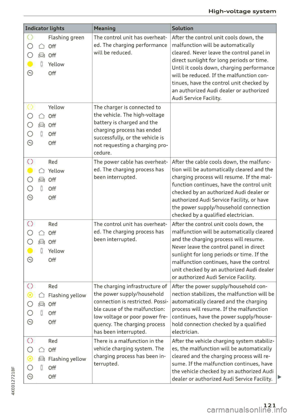
Control unit: status and malfunction indicators
at a power outlet. This can help to prevent the
electrical equipment from overheating.
The vehicle has a minimum battery charging ca-
pacity of 880 W. Therefore, if the network volt-
age is less than 200 V, charging using a house-
hold socket will only be possible if the charging
power level is set to 100%. Otherwise, the charg-
ing process will not start.
Before charging, always check if the charging
power setting that was selected last is still suita-
ble.
— To set the charging power level, press and hold
the ® button © ® fig. 87 for at least two sec-
onds.
After the charging power level is set, the status
LEDs Q, {and (will flash green one time. The
selected value (50% or 100%) is displayed on the
left or right side of the ® button.
Indicator lights Meaning Solution
O Green The charger is ready to charge, | Starting the charging process
O O Off but is not charging. => page 112.
O & off
O 0 off
9 Off
O Flashing green _| The vehicle is being charged
QO Off with the ground conductor
E off monitor activated.
0 Off
Off
Flashing green
®O®OVSSC|I®OO0O
ance will be reduced.
C Yellow ed. Possible cause of the mal-
a
& oft is being used in single-phase
mode. The charging perform-
Off
The power cable has overheat- | After the cable cools down, the malfunc-
tion will be automatically cleared. Until it
Off function: a multi-phase socket | cools down, charging performance will be
reduced. If the malfunction continues,
have the power supply/household con-
nection checked by a qualified electrician.
120
Page 123 of 308

4KE012721BF
High-voltage system
Indicator lights Meaning Solution
o> Flashing green |The control unit has overheat- | After the control unit cools down, the
O A Off ed. The charging performance | malfunction will be automatically
O B&B oft will be reduced. cleared. Never leave the control panel in
direct sunlight for long periods or time.
© 0 Yellow Until it cools down, charging performance
° Off will be reduced. If the malfunction con-
tinues, have the control unit checked by
an authorized Audi dealer or authorized
Audi Service Facility.
€) Yellow The charger is connected to
O QA Off the vehicle. The high-voltage
O B oft battery is charged and the
charging process has ended
O 0 off successfully, or the vehicle is
® Off not requesting a charging pro-
cedure.
© Red The power cable has overheat- | After the cable cools down, the malfunc-
© @ Yellow ed. The charging process has __| tion will be automatically cleared and the
O B oft been interrupted. charging process will resume. If the mal-
function continues, have the control unit
O 0 off checked by an authorized Audi dealer or
© Off authorized Audi Service Facility, or have
the power supply/household connection
checked by a qualified electrician.
Q Red The control unit has overheat- | After the control unit cools down, the
O
A Off ed. The charging process has_ | malfunction will be automatically cleared
O B oft been interrupted. and the charging process will resume.
© 8 Yeltow Never leave the control panel in direct
sunlight for long periods or time. If the
© Off malfunction continues, have the control
unit checked by an authorized Audi dealer
or authorized Audi Service Facility.
O Red The charging infrastructure of | After the power supply/household con-
© Q Flashing yellow |the power supply/household | nection stabilizes, the malfunction will be
O 2 oft connection is restricted. Possi- | automatically cleared and the charging
O 6 off ble cause of the malfunction: | process will resume. If the malfunction
low voltage or poor power fre- | continues, have the power supply/house-
© Off quency. The charging process | hold connection checked by a qualified
has been interrupted. electrician.
O Red There is a malfunction inthe | After the vehicle charging system stabiliz-
O QO Off vehicle charging system. The | es, the malfunction will be automatically
© B Flashing yellow charging process has been in- | cleared and the charging process will re-
O 6 of terrupted. sume. If the malfunction continues, have
© oH the vehicle checked by an authorized Audi
dealer or authorized Audi Service Facility.
121
Page 124 of 308

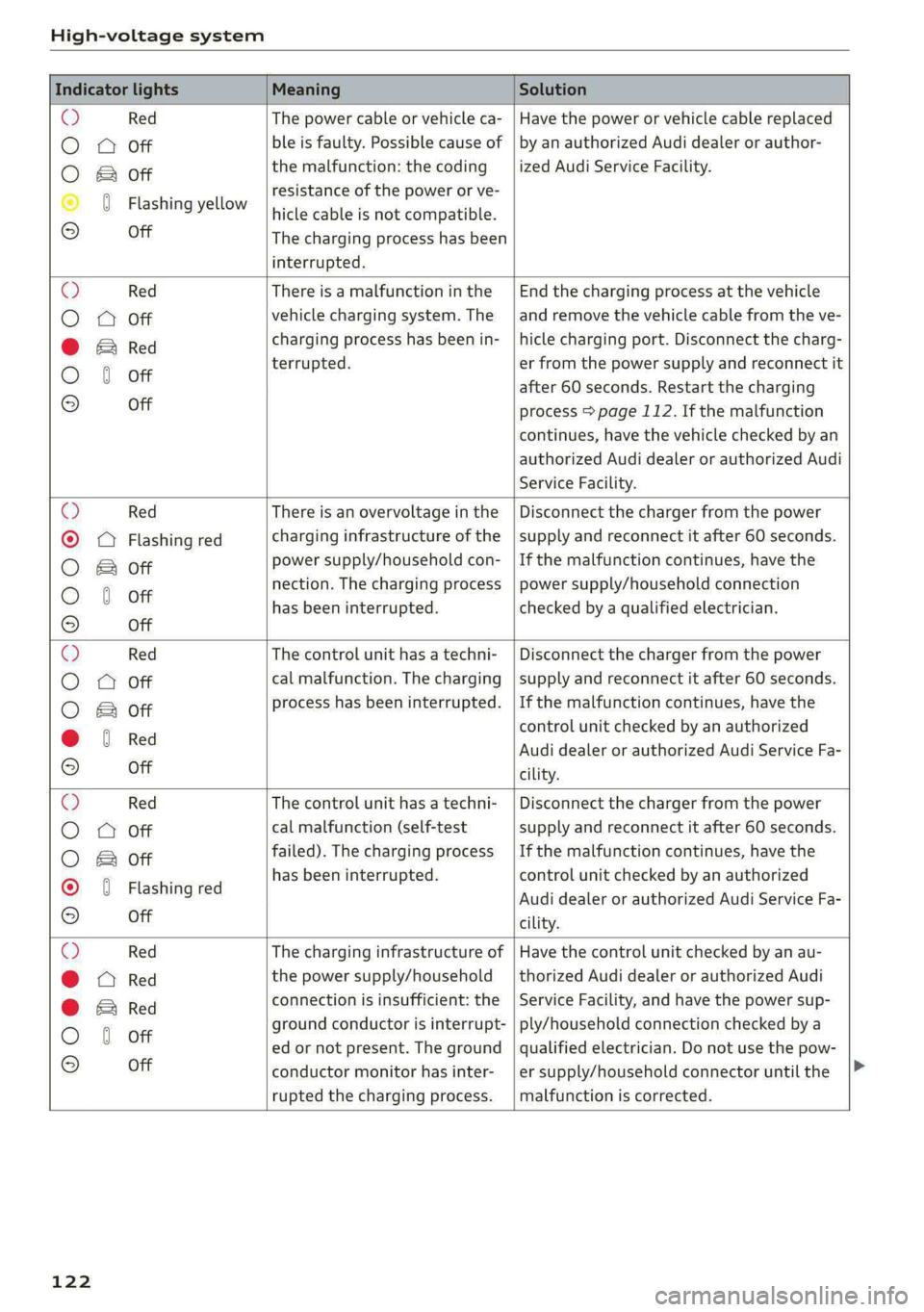
High-voltage system
Indicator lights Meaning Solution
@ Red The power cable or vehicle ca- | Have the power or vehicle cable replaced
O A Off ble is faulty. Possible cause of | by an authorized Audi dealer or author-
the malfunction: the coding ized Audi Service Facility.
O & Off
. resistance of the power or ve-
© 0 Flashing yellow hicle cable is not compatible.
© Off The charging process has been
interrupted.
@ Red There is a malfunction inthe | End the charging process at the vehicle
O QO Off vehicle charging system. The | and remove the vehicle cable from the ve-
@ Ered charging process has been in- |hicle charging port. Disconnect the charg-
O 6 of terrupted. er from the power supply and reconnect it
after 60 seconds. Restart the charging
9 Off process > page 112. If the malfunction
continues, have the vehicle checked by an
authorized Audi dealer or authorized Audi
Service Facility.
O Red There is an overvoltage inthe | Disconnect the charger from the power
© OQ Flashing red charging infrastructure of the |supply and reconnect it after 60 seconds.
O B oft power supply/household con- |If the malfunction continues, have the
O 6 oft nection. The charging process | power supply/household connection
© has been interrupted. checked by a qualified electrician.
Off
O Red The control unit has atechni- | Disconnect the charger from the power
O O Off cal malfunction. The charging | supply and reconnect it after 60 seconds.
O B oft process has been interrupted. |If the malfunction continues, have the
@ 6 Red control unit checked by an authorized
© Audi dealer or authorized Audi Service Fa-
© Off cility.
O Red The control unit has atechni- | Disconnect the charger from the power
O O Off cal malfunction (self-test supply and reconnect it after 60 seconds.
O B oft failed). The charging process | If the malfunction continues, have the
© 0 Flashi d has been interrupted. control unit checked by an authorized
ashing re Audi dealer or authorized Audi Service Fa-
OQ Off cility.
O Red The charging infrastructure of | Have the control unit checked by an au-
@ Red the power supply/household | thorized Audi dealer or authorized Audi
connection is insufficient: the | Service Facility, and have the power sup-
@ & Red
O 6 off ground conductor is interrupt- | ply/household connection checked by a
ed or not present. The ground | qualified electrician. Do not use the pow-
© Off conductor monitor has inter-
rupted the charging process.
er supply/household connector until the
malfunction is corrected.
122
Page 125 of 308

4KE012721BF
High-voltage system
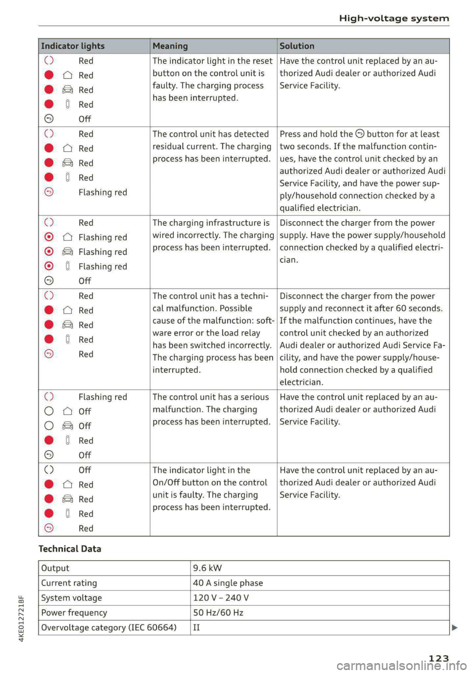
Indicator lights Meaning Solution
© Red The indicator light in the reset | Have the control unit replaced by an au-
@ CQ Red button on the control unit is | thorized Audi dealer or authorized Audi
@ BRe faulty. The charging process | Service Facility.
@ 6 Red has been interrupted.
9 Off
O Red The control unit has detected | Press and hold the © button for at least
@ X Red residual current. The charging | two seconds. If the malfunction contin-
@ Si Red process has been interrupted. | ues, have the control unit checked by an
@ 6 Red authorized Audi dealer or authorized Audi
© . Service Facility, and have the power sup-
2 Flashing red ply/household connection checked by a
qualified electrician.
O Red The charging infrastructure is | Disconnect the charger from the power
® QQ Flashing red wired incorrectly. The charging | supply. Have the power supply/household
© & Flashing red process has been interrupted. | connection checked by a qualified electri-
cian.
© { Flashing red
9 Off
O Red The control unit has atechni- | Disconnect the charger from the power
@ CO Red cal malfunction. Possible supply and reconnect it after 60 seconds.
@ Bred cause of the malfunction: soft- | If the malfunction continues, have the
@ 6 Red ware error or the load relay control unit checked by an authorized
© has been switched incorrectly. | Audi dealer or authorized Audi Service Fa-
2 Red The charging process has been |cility, and have the power supply/house-
interrupted. hold connection checked by a qualified
electrician.
O Flashing red The control unit has a serious | Have the control unit replaced by an au-
O QO Off malfunction. The charging thorized Audi dealer or authorized Audi
O 2 oft process has been interrupted. | Service Facility.
@ & Red
9 Off
© Off The indicator light in the Have the control unit replaced by an au-
@ A Red On/Off button on the control | thorized Audi dealer or authorized Audi
@ E&rRed unit is faulty. The charging Service Facility.
@ 6 Red process has been interrupted.
© Red
Technical Data
Output 9.6 kw
Current rating 40 A single phase
System voltage 120V-240V
Power frequency 50 Hz/60 Hz
Overvoltage category (IEC 60664) {II
123
Page 208 of 308

Navigation
Prefer Electrify America charger station
When this function is switched on, the e-tron
route planner will give preference to Electrify
America charging stations.
Route information
When this function is switched on and route
guidance is active, route information
= page 199, fig. 136 is displayed. The next ma-
neuver will be displayed at the bottom. POIs and
traffic information will also be displayed. Press
route
information to display a preview of the next
maneuver on the map. You can switch the follow-
ing information on or off in route information.
— Points of interest along the route
— Traffic incidents
Presentation mode
In presentation mode, the system simulates driv-
ing on the display along the planned route with-
out the vehicle actually moving. You can use
Specify starting point when you would like to
calculate a route starting from a location other
than the current vehicle position, for example.
Simulating route guidance: start route guidance
and press presentation mode.
G@) Tips
You can change the volume of navigation an-
nouncements while one is playing > page 28.
206
Page 280 of 308

Fuses and bulbs
— The following table does not list fuse loca-
tions that are not used.
— Some of the equipment listed in the follow-
ing tables applies only to certain model ver-
sions or certain optional equipment.
[RAZ-0876 Fig. 175 Front passenger footwell: fuse panel with plastic
clip
Fig. 174 Right side of the motor compartment: fuse panel
with plastic clip
No. | Equipment
Charging port door
Climate control system compressor
High-voltage battery
High-voltage charger
Thermal management
NO)
a)
BR)
Nye
Electric drive system
B B High-voltage charger
13 | Thermal management
Fig. 176 Front passenger footwell: fuse panel with plastic 14 | Windshield washer system control module atip
15 | High-voltage battery water pump
16 | Windshield wipers The fuse assignment on right-hand drive vehicles
is a mirror image of this.
17 | Thermal management
18 | Thermal management
19 | Thermal management No. | Equipment
21 | Electronic Stabilization Control (ESC) 4 Climate control system, fragrance system,
lonizer
4 |Head-up display
5 |Audi music interface, USB input
6 |DVD drive
7 |Steering column lock
8 |Upper/lower display >
278