brake light AUDI Q3 2017 Owner´s Manual
[x] Cancel search | Manufacturer: AUDI, Model Year: 2017, Model line: Q3, Model: AUDI Q3 2017Pages: 236, PDF Size: 58.93 MB
Page 81 of 236
00
00
......
"' ,....
"' ...... 0 0 :::,
00
@ Tips
The cruise control system cannot maintain
the speed cons istently if you are driving on
steep hills. The vehicle weight ca uses the
speed to increase. Due to th is, shift into a
lower gear in t ime or apply the brakes .
Changing speed
Applies to: vehicles with cruise control system
~ To inc rease or decrease the speed in incre
me nts, push the lever towa rd
0 10 ~ page 78,
fig. 80.
~ T o inc rease o r decrease the speed quickly , hold
the leve r in the
0 10 direction until the de
si red speed is displayed .
Overriding the cruise control system
Applies to: veh icles with cru ise control system
You can a lso press the accelerator pedal down to
increase your speed, for example if you want to
pass someone. The speed you set earlier w ill re
sume as soon as you release the accelerator ped
al.
However, if you are exceeding the stored speed
by a cons iderable amount for a long time, the
cru ise control system will temporar ily switch off .
The
M;ll)~i~ (USA models) 1 B (Canada models) in
d icator light in the instrument cluster turns off
and the sto red speed is maintai ned.
Preselecting the speed
Applies to: vehicles with cruise control system
You can pre-select your desired speed when the
vehicle is stationary.
~ Switch the ign ition on .
~ Pull the lever into position (D c:> page 78,
fig . 80 .
~ To inc rease o r decrease the speed, push the lev-
er toward
0 10 .
~ To store the speed disp layed, release the lever .
This f unct io n ma kes it possib le, for examp le, to
save the speed yo u wan t before dr iving on the
hi ghway. Once on the h ighway, ac tiva te the
cru ise control by pu lling the lever toward
(D .
Switching off
Applies to: vehicles with cruise control system
Temporary deactivation
~ Press the brake pedal, or
Assist
~ Press the lever into position @ (not clicked into
p lace)
c:> page 78, fig. 80, o r
~ Dr ive fo r longer t han five minutes at mo re than
6 mph ( 10 km/h) above the sto red speed .
Switching off completely
~ Press the lever into position @(clicked into
place), o r
~ Switch the ignit ion off.
The speed you stored will be maintained if the
c ruise contro l has been switched off temporarily .
T o resume the stored speed, re lease the bra ke
pedal and pull the lever into pos ition
(D .
Switching the ignition off w ill erase the stored
speed .
,&. WARNING
You should only resume the s to red speed if it
i s no t too high fo r exis ting t raffic conditions.
Otherw ise you can inc rease the risk of an acci
dent .
79
Page 94 of 236
Intelligent Technology
Intelligent Technology
Electronic Stabilization
Control (ESC)
Description
Elect ronic Stabilization Control (ESC) suppo rts
driver safety.
It red uces the risk of slipping and
improves dr iving stability. ESC detects crit ica l sit
uations such as the veh icle oversteering and un
dersteering or the wheels are sp inning. The vehi
cle is stabilized by app lying the brakes or reduc
ing engine torque. When ESC engages, the
G1 i n
d icator light blinks in the inst rument cluste r.
The fo llow ing systems are integrated in the ESC:
Anti -lock b raking system (ABS)
ABS prevents the whee ls from loc king when brak
i n g . The vehicle can sti ll be steered even d uring
hard brak ing. Apply steady press ure to the brake
pedal. Do not pump the pedal. A puls ing in the
brake pedal indicates that the system is acting to
stabilize the vehicle .
Brake assi st sy stem
The brake assist system can dec rease braking dis
tance. It increases brak ing power when the driver
presses the brake pedal quick ly in emergency sit
uations . You must press and hold the brake pedal
until the dangerous situat io n is over .
Anti- s lip regulation (ASR )
ASR reduces eng ine power when the drive w heels
begin spinning and adapts the force to the road
conditions. This makes it easier to start, acceler
ate and dr ive up h ills .
Electron ic differential lock (EDL)
The ED L bra kes wheels that a re spinning and
transfers the drive power to the other drive
wheel or wheels if the ve hicle is equipped with a ll
wheel drive*) . This funct ion is not ava ilable at
h igher speeds.
In extreme cases, EDL automatically switches off
to keep the brake on the braked wheel from over heating. The vehicle is still work ing correctly. EDL
92
will switch on again au tomatically when condi
tions have returned to normal.
Steering recommendation
The ESC he lps to s tabili ze the vehicle by cha ng ing
t h e s teer ing torque .
Selective wheel torque control
Selective wheel to rque cont rol is used when d riv
i ng o n curves . The front whee l on the inside of
t h e curve or both wheels on the i nside of th e
cu rve are braked se lective ly as needed. This al
l ows mo re pre cise driving in curves .
Automatic post -collision braking system
The "automat ic post -coll is io n braking system"
can help to reduce the risk of sl iding and of addi
tiona l co llisions after an acc ident. If the a irbag
c ontro l modu le detects a collision above a cert ain
vehicle speed, the veh icle is braked by the ESC.
The veh icle does n ot brake automatically if:
- the drive r presses the accelerator pedal, or
- the bra king force generate d by the pressed
brake pedal is greater than the b raking force
that would be in itiated by the system, or
- the ESC, the bra ke system or the vehicle elect ri
cal system are not functioning.
A WARNING
- The ESC and its integ rated systems can not
overcome the lim its imposed by natura l
p hys ica l laws. This is es pec ially impo rtan t
on sl ippery or wet roads. If the systems be
gi n a cting to stabili ze yo ur vehicle, you
s hould immedi ately alte r your speed to
match the road and tra ffic conditions . Do
not let t he in creased safety provi ded tempt
you into taking risks . This could increase
your r is k of a coll is ion.
- Please note the r is k of a coll is ion increases
when dr iv ing fast, especially th rough c urves
and on slippery or wet roa ds, and when dr iv
ing too close to objects ahead. The ESC and
its integrated systems cannot always pre
ve nt co llisions - there is st ill a risk of acci
dents!
Page 96 of 236
Intelligent Technology
_&. WARNING
You should only switch offroad mode on or
switch ESC/ ASR off if your driving abilities
and the traff ic conditions perm it. There is a
r isk of slid ing.
- The stabilization function is limited when
offroad mode is switched on. The driving
wheels co uld spin and the vehicle could
swerve , especially on slick or slippery road
surfaces.
- T here is no vehicle stab ilizat ion when ESC/
ASR are switched off .
Hill descent assist
Applies to: vehicles with hill hold assist
Hill descent assist makes it possible to drive
down a hill at a constant speed.
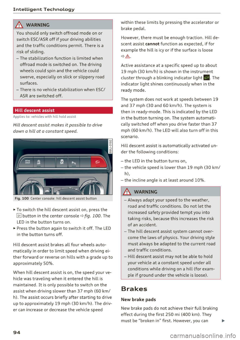
Fig . 100 Center console: hill descent assist button
.,. To switch the hill descent assist on, press the
~ button in the center console c:> fig. 100. The
LED in the button turns on.
.,. Press the button again to switch it off. The LED
in the button turns off.
Hill descent assist brakes all four wheels auto
matically in order to limit speed when driving ei
ther forward or reverse on hills with a grade up to
approx imately 50%.
When hill descent assist is on, the speed your ve hicle was traveling when it entered the hill is
maintained. It is only possible to switch on the
assist when driving slower than 37 mph (60 km/
h). The assist occurs br iefly after start ing to drive
up to approximately 19 mph (30 km/h). The driv
er can increase or decrease the vehicle speed
94
within these limits by pressing the accelerator or
brake peda l.
However, there must be enough tract ion. Hill de
scent assist
cannot function as expec ted, if fo r
example the hill is icy or if the surface is loose
c:>,& .
Active assistance at a specific speed up to about
19 mph (30 km/h) is shown in the instrument
cluster through a blinking indicator light •. The
indicator light shines continuously when in the
ready mode.
The system does not work at speeds between 19
and 37 mph (30 and 60 km/h). The system is
then in ready-mode . This is indicated by the LED
i n the button turning on. The system automat i
ca lly switched off when you drive faster than 37
mph (60 km/h) . The LED will also turn off in this
scenario.
Hill descent assist is automatically activated un
der the following conditions:
- the LED in the button turns on,
- the vehicle speed is lower than 19 mph (30 km/
h),
- the incline angle is at least around 10%.
_&. WARNING
-Always adapt your speed to the weather,
road and traffic conditions. Do not let the
increased safety provided tempt you into
taking risks, because this increases the risk
of an accident .
-
-The hill descent ass ist system cannot over
come the laws of physics. Your driving style
must always be adapted to the current road
and traffic conditions.
- Hill descent ass ist may not be ab le to hold
your vehicle at a constant speed under all
conditions while dr iv ing on a hill (for exam
ple if ground u nder the vehicle is loose).
Brakes
New brake pads
New brake pads do not achieve their full braking
effect during the first 250 mi (400 km). They
must be "broken in" first. However, you can ..,.
Page 97 of 236
00
00
......
"' ,....
"' ...... 0 0 :::,
00
compensate for the slightly reduced bra king
force by pressing firmly on the brake peda l. Avoid
heavy braking during the break -in period .
Operating condit ion s and dr iving habits
The brakes on today's automobiles a re sti ll s ub
ject to wear, depend ing largely on ope rating con
ditions and driving habits¢& . On vehicles that
are either driven most ly in stop-and -go city traf
fic or are driven hard, the brake pads should be
checked by your authorized Aud i dealer more of
ten than specified in the
Warran ty & Mainte
n anc e boo kle t .
Failure to have your brake pads
inspected can resu lt in reduced brake perform
ance.
On steep slopes, you should use the braking ef
fect of the eng ine. This way, you prevent unnec
essary wear on the brake system . If you must use
your brakes, do not hold the b rakes down cont in
uously. P ump t he b rakes at intervals.
Operating no ise
Noises may occur when braking depend ing on the
speed, braking force and outs ide cond itions such
as tempe rature and humidity .
Effect of water or road salt
In certain situations, for example after driving
through water, in heavy ra in, after overnight con
densat ion or after washing your car, the braking
effect can be reduced by mo isture or ice on the
brake rotors and brake pads . The brakes must be
"dr ied" fi rst w it h a few careful brake applica
tions .
At highe r speeds and with the windsh ield w ipers
turned on, the brake pads press aga inst the brake
rotors for a short amount of time. This action,
which is not felt by the d river, happens a t regular
i nte rvals and ens ures a better reaction time fo r
the brakes in wet weather.
The bra king effect can also be redu ced if you are
d riving on salted roads and you do not apply t he
b ra kes fo r long pe riods of time. The layer of sa lt
on the brake rotors and brake pads m ust be worn
off first when the b rakes are applied¢& .
Intellig ent Technology
Corrosion
Leaving t he vehicle pa rked fo r lo ng periods of
t ime, low mileage and avoiding heavy braking
can contrib ute to corrosion on the brake rotors
and to dirty brake pads .
If you usua lly avoid heavy bra king or if there is
corrosion present, occasiona l heavy braking at
high speeds is recommended to clean the brake
rotors and pads¢& .
Brake system malfunction
if you no tice that the b rake peda l t ravel has sud
denly
gotten larger, then a b rake c ircuit may have
f ailed ¢ & .
Low brake fluid level
When the brake fluid level is low, malfu nctions in
the b rake system may occur. The b rake fl uid level
is e lec tron ically moni tored.
Brake booster
The brake booster amplifies the pressure you ap
ply to the brake pedal.
It only works when the en
gine is running~ &.
Brake lining wear statu s
Brake lining wear may be checked by visual in
spect ion of the condition of the brake pads
t h rough the openings in the wheel. If necessary,
the wheel may be removed for this i nspection
¢ page 198, Replacing wheels .
,&. WARNING
-New brake pads don't have the bes t stop
ping power and m ust be "broken-in" during
the initial 250 mi (400 km) . You
can com
pensate for this by pressing the brake pedal
more firmly . This a lso applies later when
new pads are installed.
- You shou ld perform braking maneuvers for
the purpose of cleaning the brake system
only if road condit ions permit. Other road
users must not be put at r isk - you may
cause an accident!
- Before descending a steep grade, reduce
speed a nd sh ift transmission into a lower
95
Page 98 of 236
Intelligent Technology
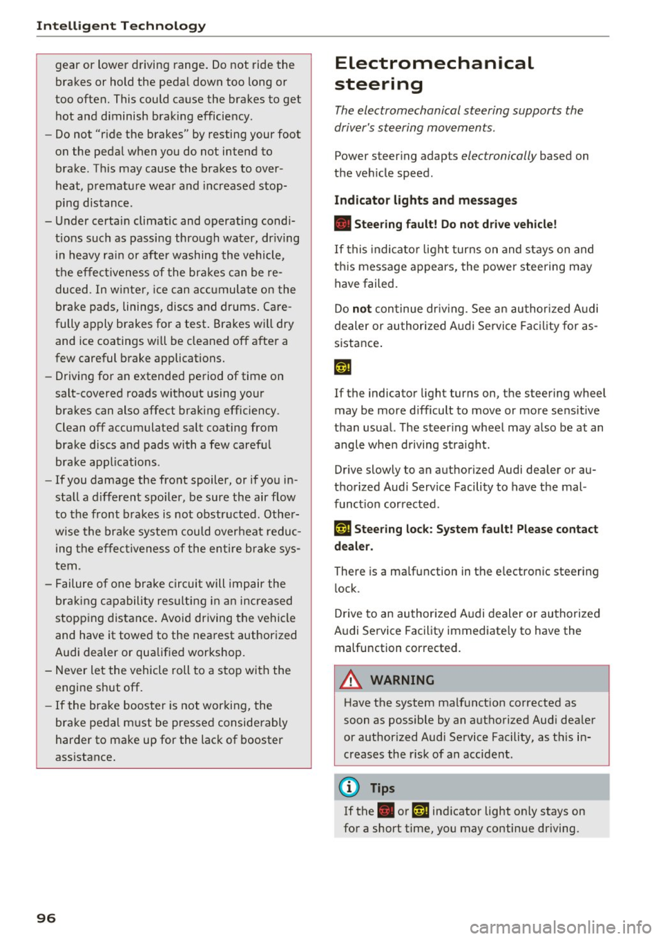
gear or lower driving range. Do not ride the
brakes or hold the pedal down too long or
too often. This could cause the brakes to get hot and diminish braking efficiency .
- Do not "ride the brakes" by resting your foot
on the pedal when you do not intend to
brake. This may cause the brakes to over
heat, premature wear and increased stop
ping distance.
- Under certain climatic and operating condi
tions such as passing through water, driving in heavy rain or after washing the vehicle ,
the effectiveness of the brakes can be re
duced . In winter, ice can accumulate on the
brake pads, linings, discs and drums . Care
fully apply brakes for a test. Brakes will dry and ice coatings will be cleaned off after a
few careful brake applications.
- Driving for an extended period of time on
salt-covered roads without using your
brakes can also affect braking efficiency .
Clean off accumulated salt coating from
brake discs and pads with a few careful
brake applications .
- If you damage the front spoiler, or if you in
stall a different spoiler, be sure the air flow
to the front brakes is not obstructed. Other
wise the brake system could overheat reduc
ing the effectiveness of the entire brake sys
tem.
- Failure of one brake circuit will impair the
braking capability resulting in an increased
stopping distance. Avoid driving the vehicle
and have it towed to the nearest authorized
Audi dealer or qualified workshop.
- Never let the vehicle roll to a stop with the
engine shut off.
- If the brake booster is not working, the
brake pedal must be pressed considerably
harder to make up for the lack of booster
assistance.
96
Electromechanical
steering
The electromechanical steering supports the
driver's steering movements .
Power steering adapts electronically based on
the vehicle speed .
Indicator lights and messages
• Steering fault! Do not drive vehicle!
If this indicator light turns on and stays on and
this message appears, the power steering may
have failed.
Do
not continue driving . See an authorized Audi
dealer or authorized Audi Service Facility for as
sistance.
If the indicator light turns on, the steering wheel
may be more difficult to move or more sensitive
than usual. The steering wheel may also be at an
angle when driving straight.
Drive slowly to an authorized Audi dealer or au
thorized Audi Service Facility to have the mal
function corrected .
(;r, lj Steering lock: System fault! Please contact
dealer.
There is a malfunction in the electronic steering
lock.
Drive to an authorized Audi dealer or authorized
Audi Service Facility immediately to have the malfunction corrected.
A WARNING
Have the system malfunction corrected as
soon as possible by an authorized Audi dealer
or authorized Audi Service Facility, as this in
creases the risk of an accident .
{!) Tips
If the . or 'T j indicator light only stays on
for a short time, you may continue driving.
-
Page 194 of 236
Care and cleaning
wash operator to reduce the risk of acci
dents.
- To reduce the risk of cuts, protect yourself
from sharp metal components when wash ing the underbody or the inside of the wheel
housings.
- After washing the vehicle, the braking effect
may be delayed due to moisture on the
brake rotors or ice in the winter. This in
creases the risk of an accident. The brakes
must be dried first with a few careful brake
applications.
(D Note
- If you wash the vehicle in an automatic car
wash, you must fold the exterior mirrors in
to reduce the risk of damage to the mirrors.
Power folding exterior mirrors* must only
be folded in and out using the power folding
function.
- To reduce the risk of paint damage, do not
wash the vehicle in direct sunlight. -
To reduce the risk of damage to the surface,
do not use insect removing sponges, kitchen
sponges or similar items.
- Matte finish painted vehicle components:
- To reduce the risk of damage to the sur-
face, do not use polishing agents or hard
wax.
- Never use protective wax. It can destroy
the matte finish effect.
- Do not place any stickers or magnetic
signs on vehicle parts painted with matte
finish paint. The paint could be damaged
when the stickers or magnets are re
moved.
@ For the sake of the environment
Only wash the veh icle in facilities spec ially de
signed for that purpose. This will reduce the
risk of dirty water contaminated with oil from
entering the sewer system.
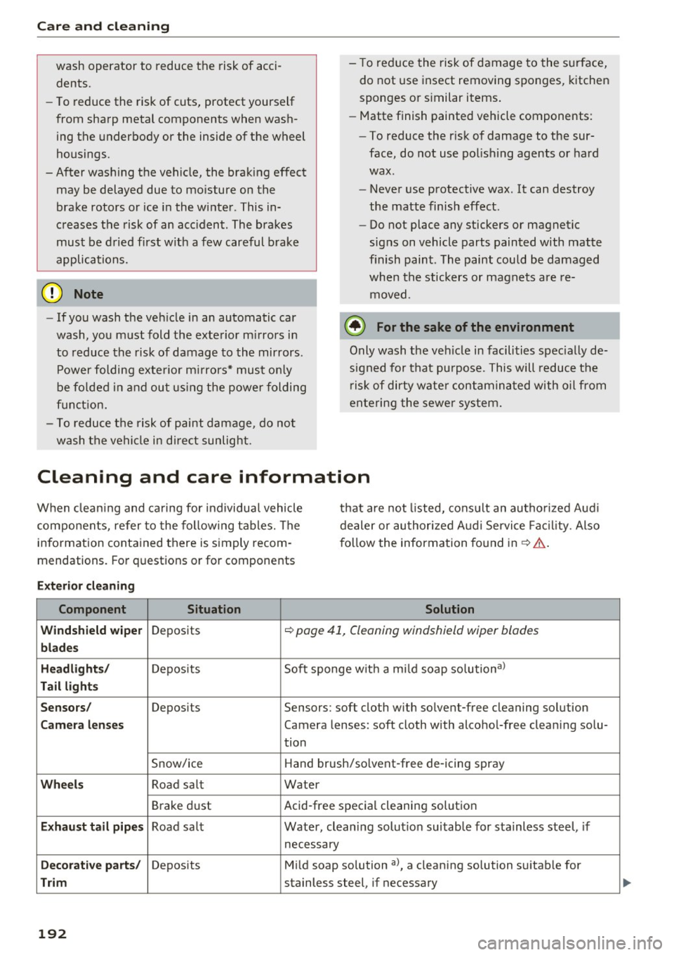
Cleaning and care information
When clean ing and caring for individual vehicle
components, refer to the following tables. The
information contained there is simply recom
mendations. For quest ions or for components that are
not listed, consult an authorized Aud i
dealer or authorized Audi Service Facility. Also
follow the information found in¢&..
Exterior cleaning
Component Situation Solution
Windshield wiper
Deposits ¢ page 41, Cleaning windshield wiper blades
blades
Headlights/
Deposits Soft sponge with a mi ld soap solutiona >
Tail lights
Sensors/
Deposits Sensors: soft cloth with solvent-free cleaning solution
Camera lenses Camera lenses: soft cloth with alcohol-free cleaning solu-
tion
Snow/ice Hand brush/so
lvent-free de -icing spray
Wheels Road salt Water
Brake dust Acid-free special cleaning solution
Exhaust tail pipes Road salt Water, cleaning solution suitable for stainless steel, if
necessary
Decorative parts/ Deposits Mild soap solution al, a cleaning solution suitable for
Trim stainless steel, if necessary
192
Page 204 of 236
Emergency assistance
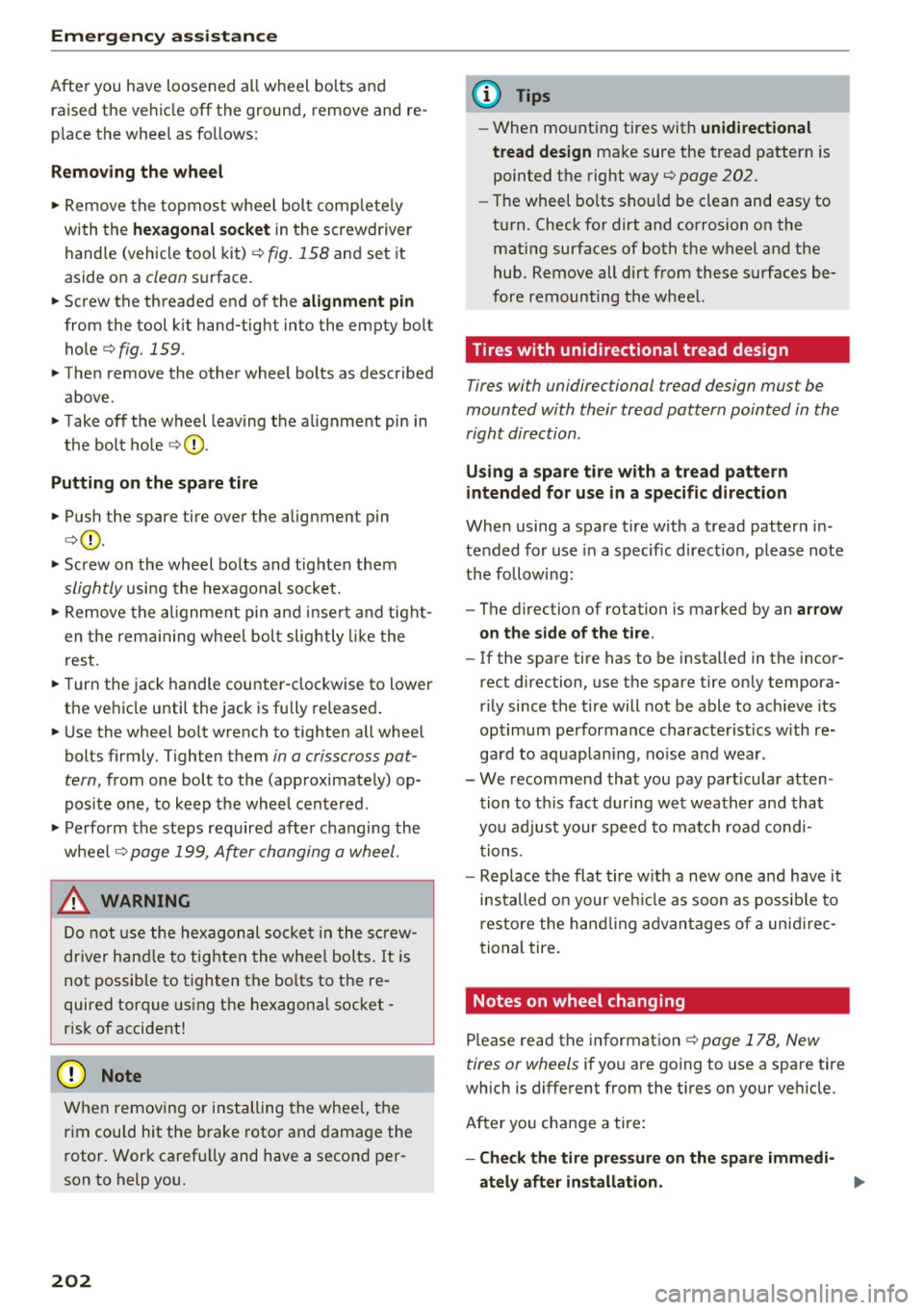
After you have loosened a ll wheel bo lts and
raised the vehicle off the ground, remove and re
p lace the whee l as fo llows:
Removing the wheel
.,. Remove the topmost wheel bol t comp letely
with the
he xagonal socket in t he screwd river
hand le (vehicle tool kit)
¢ fig. 158 and set it
aside on a
clean s ur face.
.,. Screw the threaded end of the
alignment pin
from the tool k it hand-tight into the empty bolt
hole¢
fig. 159 .
.,. The n remove the other wheel bolts as described
above.
.,. Take off the wheel leav ing the a lignment pin in
the bo lt hole ¢ 0.
Putting on the spare tire
.,. Push the spare tire over the alig nment pin
¢ (D .
.,. Screw on the wheel bo lts and tighten them
slightly using the hex agonal socke t.
.,. Remove the a lignment pi n an d in se rt an d tight
en t he rem aining wheel bol t slightly like the
res t.
.,. Turn the jack handle counter-clockwise to lower
the ve hicle until the jack is fully re leased .
.,. Use the wheel bolt wrench to tighten all wheel
bolts firmly. Tighten them
in a crisscross pat
tern,
from one bol t to the (app roximately) op
pos ite one, to keep the whee l cente red .
.,. Perfo rm the steps req uire d afte r changing the
whee l ¢
page 199, After changing a wheel.
&, WARNING
Do not us e the he xagon al so cke t in t he screw
dr iver han dle to tig hten the wheel bol ts . I t is
not poss ib le to tighten t he bo lts to the re
quired torque usin g t he he xagonal socket -
r is k of accident!
(D Note
W hen removi ng or inst alling the whee l, the
r im cou ld hit the brake roto r and dama ge t he
rotor . Work ca ref ull y and have a seco nd per
son to help you.
202
(D Tips
- When mo unting tires with unidirectional
tread design
make sure the trea d pattern is
pointed the right way¢
page 202.
-The wheel bolts s hould be clean an d easy to
t u rn. Check fo r dirt and corrosion on the
matin g surfaces of both the wheel and the
hub. Remove all dirt from these s urfaces be
fore remounting the whee l.
Tires with unidirectional tread design
Tires with unidirectional tread design mus t be
mounted with their tread pattern pointed in the
right direction .
Using a spare tire with a tread pattern
intended for use in a specific direction
When using a s pare tire w ith a t read patter n in
te nded for use in a specif ic direct ion, please note
t h e followi ng :
- The d irection of rotation is marked by an
arrow
on the side of the tire .
-If the spare tire has to be installed in the incor
rect direction, use the spare tire on ly tempora
r il y since the tire will not be able to ac hieve its
op timum performa nce characterist ics w ith re
gard to aquap la ni ng, no ise a nd wear.
- W e recommend that you pay part icu lar atten
t ion to th is fact d urin g we t wea ther an d that
you a djust your spee d to matc h road cond i
tion s.
- Rep lace the flat tire w it h a new one an d have it
inst alled o n your ve hicle as soon as possib le to
res tore the h andlin g advan tage s of a unidir ec
tional tire .
Notes on wheel changing
Please read t he informat ion ¢ pa ge 17 8, New
tires or wheels
if yo u ar e go ing to use a spare tire
which is d ifferent from the t ires o n your ve hicle.
A ft er yo u ch an ge a tire:
- Check the tire pressure on the spare immedi-
ately after installation. .,.
Page 208 of 236
Fuses and bulbs
(D Tips
- The following table does not list fuse loca
tions that are not used.
- Some of the equipment listed in the follow
ing tables applies only to certain model ver
sions or certain optional equipment.
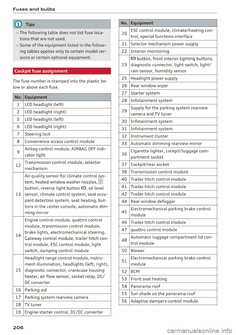
Cockpit fuse assignment
The fuse number is stamped into the plastic be
low or above each fuse.
No. Equipment
1 LED headlight (left)
2 LED headlight ( right)
5 LED headlight (left)
6 LED headlight (right)
7 Steering lock
8 Convenience access contro l module
9
Airbag control module, AIRBAG OFF indi-
cator light
12
Transmission control module, selector
mechanism
Air quality sensor for cl imate control sys-
tern, heated w indow washer nozzles ,
lj]
button, reverse light button<®>, oi l level
13 sensor, climate contro l system, seat occu-
pant detection system, seat heating, but-
tons in the center console, automatic dim-
ming mirror
Engine control module, quattro control
modu le, transmission control module,
14
brake lights, electromechanica l steering,
Gateway control module, trai ler hitch con-
trol module, ESC contro l module, light
switch, damping control module
Headlight range control module , instru-
ment illumination, headlights (left, right),
15 diagnostic connector, crankcase housing
heater, a ir flow sensor, socket relay, DC/
DC converter
16 Park ing aid
17 Parking system rearview camera
18 TV tuner
19 Engine starter control, DC/DC converter
206
No . Equipment
20
ESC contro l module, climate/heating con-
trol, special functions interface
21 Selector mechanism power supply
22 Interior monitoring
© button, front interior lighting buttons,
23 diagnostic connector, light switch, light/
rain sensor, humidity sensor
25 Headlight power supply
26 Rear window wiper
27 Starter system
28 Infotainment system
29
Supply for the parking system rearv iew
camera and TV tuner
30 Infotainment system
31 Infotainment system
32 Instrument cluster
33 A utomat ic dimming rearview mirror
36
Cigarette lighter, cockpit/luggage com-
partment socket
37 Cockpit/rear socket
38 Transmission control module
40 Trailer hitch control module
41 Tra iler hitch control module
42 Trailer hitch control module
44 Rear window defogger
45
Electromechanical parking brake control
module
46 Trailer hitch control module
47 quattro control module
48 Aut omat ic lu ggage compartment lid con-
tro l module
so Blower
51
Electromechanical parking brake control
module
52 BCM
53 Fr ont seat heating
54 Panorama roof
SS Sun shade on the panorama
roof
56 Adaptive dampers control module
Page 209 of 236
00
00
......
"' ,....
"' ...... 0 0 :::,
00
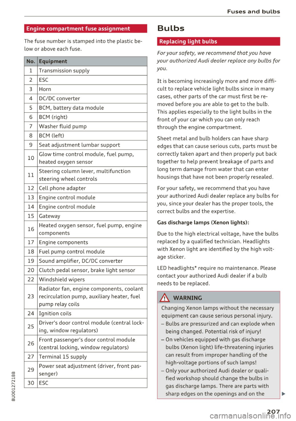
Engine compartment fuse assignment
The fuse number is stamped into the plastic be
low or above each fuse.
No. Equipment
1 Transmiss ion supply
2 ESC
3 Horn
4 DC/DC
converter
5 BCM, battery data module
6 BCM (right)
7 Washer fluid pump
8 BCM (left)
9 Seat adjustment lumbar support
10 Glow time
control module, fuel pump,
heated oxygen sensor
11 Steering
column lever, multifunction
steer ing whee l controls
1 2 Cell phone adapter
13 En
gine control module
14 Engine control module
15 Gateway
16 Heated oxygen sensor, fuel pump, eng
ine
components
17 Engine components
18 Fue
l pump control module
19 Sound amplifier, DC/DC converter
20 Clutch pedal sensor, brake light sensor
22 Windshield wipers Radiator fan, engine components, coolant
23 recirculation pump, auxiliary
heater, fuel
pump relay coils
24 Ignition coils
25 Driver's door
control module (central lock-
ing, window regulators)
26 Front passenger's door control module
(centra
l locking, window regulators)
27 Term inal 15 supply
29 Power seat adjustment (driver,
front pas-
senger)
30 ESC
Fu ses an d bulb s
Bulbs
Replacing light bulbs
For your safety, we recommend that you have
your authorized Audi dealer replace any bulbs for
you .
It is becoming increasingly more and more diffi
cult to replace vehicle light bulbs since in many
cases, other parts of the car must first be re
moved before you are able to get to the bulb .
T his applies especially to the light bulbs in the
front of your car which you can only reach
through the engine compartment .
Sheet metal and bu lb holders can have sharp
edges that can cause serious cuts, pa rts must be
correctly taken apart and then properly put back
together to help prevent breakage o f parts and
long term damage from water that can enter
housings that have not been properly resealed.
For your safety, we recommend that you have
your authorized Aud i dea ler rep lace any bulbs fo r
you, since your dealer has the proper tools, the
correct bulbs and the expertise.
Gas di schar ge la mps (Xe no n ligh ts):
Due to the high electr ical voltage, have the bulbs
rep laced by a qualified technician. Headlights
with Xenon light are identified by the hig h volt
age st icker.
LED headlights* require no maintenance . Please
contact your authorized Audi dea ler if a bulb
needs to be replaced.
_&. WARNING
Changing Xenon lamps wi thout the necessary
equipment can cause serious personal injury .
- Bulbs are pressu rized and can explode when
be ing changed. Potent ial ris k of injury!
- On veh icles equipped with gas disc harge
bu lbs (Xenon light) life-threatening injuries
can resu lt from improper handling of the
high-vo ltage portions of such lamps!
- Only your authorized A udi dealer or quali
f ied workshop sho uld change the bulbs in
gas discharge lamps. There are parts with
sharp edges on the openings and on the
207
Page 212 of 236
Emergency situations
@ Tips
The discharged battery must be properly con
nected to the vehicle's electrical system .
When jump starting or charging the battery,
never connect the negative ground cable to
the battery negative post because the battery
manager system must be able to detect the
battery's state of charge . Always connect the
negat ive ground cable to the negative ground
pos t of the battery manager control unit.
Use of jumper cables
Make sure to connect the jumper cable clamps in
exactly the order described below!
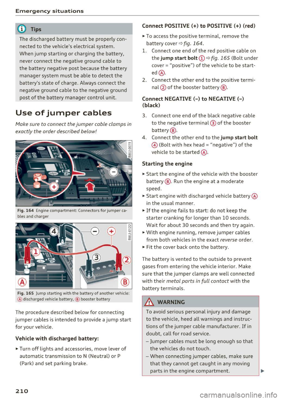
Fig. 164 Engine compartmen t: Connectors fo r ju m pe r ca
bles and charger
Fig. 165 J u mp starting w ith the battery of another vehicle :
@ discha rged vehicle bat te ry, @ booste r battery
The procedure described below for connecting
jumper cables is intended to provide a jump start
for your veh icle.
Vehicle with discharged battery:
.. Turn off lights and accessories, move lever of
automatic transmission to
N (Neutral) or P
(Park) and set park ing brake .
210
Connect POSITIVE(+) to POSITIVE (+) (red)
.. To access the positive terminal, remove the
battery cover
r:!) fig. 164.
1. Connect one end of the red positive cable on
the
jump start bolt (D ~ fig. 165 (Bolt under
cover= "positive") of the vehicle to be start
ed @.
2. Connect the other end to the positive termi-
nal@ of the booster battery @.
Connect NEGATIVE(-) to NEGATIVE(-)
(black)
3. Connect one end of the black negative cable
to the negative terminal ® of the booster
battery @.
4. Connect the other end to the
jump start bolt
© (Bolt with hex head= "negative") of the
vehicle to be started @.
Starting the engine
.,. Start the eng ine of the vehicle with the booster
battery @. Run the eng ine at a moderate
speed .
.,. Start engine w ith discharged vehicle battery@
in the usual manner.
.. If the engine fails to start: do not keep the
starter cranking for longer than 10 seconds.
Wait for about 30 seconds and then try again .
.. With engine running, remove jumper cables
from both vehicles in the exact
reverse order .
.,. Fit the cover back onto the battery .
The battery is vented to the outside to prevent gases from entering the vehicle interior . Make
sure that the jumper clamps are well connected
with their
metal parts in full contact with the
batte ry terminals.
A WARNING
To avoid serious personal inju ry and damage
to the veh icle, heed all warnings and instruc
tions of the jumper cable manufacturer.
If in
doubt, call for road service.
- Jumper cables must be long enough so that
the vehicles do not touch .
- When connecting jumper cables, make sur e
that they cannot get caug ht in any moving
pa rts in the engine compartment. ..,.