engine AUDI Q3 2017 Owner´s Manual
[x] Cancel search | Manufacturer: AUDI, Model Year: 2017, Model line: Q3, Model: AUDI Q3 2017Pages: 236, PDF Size: 58.93 MB
Page 168 of 236
Check ing and F illing
areas, into open streams or down sewage
drains .
- Recycle used engine oil by taking it to a used
engine oil collection facility in your area, or
contact a service station .
Cooling system
Coolant
The engine coo ling system is filled wi th a mixture
of pur ified w ate r a nd coolan t addit ive at the fa c
tory . T h is coo lant must not be not changed.
The coolant leve l is monito red throug h the . in
d icator light~
page 13 . Howeve r, we do re com
mend occasionally check ing the coo la nt level
manually.
I f you must add coolant, use a m ixt ur e of wa ter
and coolant addit ive. M ixing the coolant additive
with d istilled wate r is recommen ded .
Coolant additive
The coolant additive is made of a nti-freezi ng a nd
corros ion protection agents . Only use the fo llow
i n g coolant add it ives. These additives may be
mixed w it h each other.
Coolant additive Specification
G13 TL774J
G12++ T
L 774 G
The amount of coo lant additive that needs to be
mixed wit h wate r depends on the climate where
the vehicle will be operated . If the coolant addi
tive percentage is too low, the coolant can freeze
and damage the engine.
Coolant Freeze protec-
additive tion
Warm reg ions min . 40% m in . -13 °F
max . 45% (
- 25
°()
Co ld regions min. 50% max
. -40 °F
max. 55% (-40 °()
0 Note
- Befo re the start of winter, have your author
i zed Audi dealer or authorized A udi Service
Fac ility check if the coolant additive in you r
166
vehicle matches t he percentage app ropriate
for the climate . This is especially important
when driving in colder climates.
- If the app ropriate coo lant additive is not
available in an eme rgency, do not add any
other additive. You could damage the en
gine. If this happens, only use water and re
store the correct m ixture ratio with t he
specified coo lant add itive as soo n as poss i
bl e.
- Only ref ill w ith new coolant.
- Radiator sealant must not be mixed with
the coolant.
· Adding coolant
Fi g. 14 3 En gin e compartment: coo lant expa nsio n ta nk
cove r
Observe the safety precautions ~.& in Working
in the engine compartment on page 159 .
Checking the engine coolant level
.. Park the vehicle on a level surface .
.. Switch the ignit io n off.
.. Read the coolant level on the coolant expansion
t ank ~
page 162, fig. 140. The coolant leve l
m ust be be twee n the m arkings when the en
gi ne i n co ld. W hen t he engine is warm it can be
slightly above the upper mar king.
Adding coolant Requirement: there must be a residua l amount of
coolan t in the expansion tank ~(}).
.,. Let the engi ne cool down .
.. Place a clot h over the coolant expans ion tank
cap and unscrew the cap counte rclockw ise
~ .& -
Page 169 of 236
00
00
......
"' ,....
"' ...... 0 0 :::,
00
~ Add coolant mixed in the correct ratio
¢ page 166 up to the upper marking.
~ Make sure that the fluid level rema ins stable.
Add more coolant if necessary.
~ Close the cap securely.
Coolant loss usually indicates there is a leak. Im
mediately drive your vehicle to an authorized
Audi dealer or authori zed Audi Service Facility
and have the cooling system inspected. If the
cooling system is not leaking, a loss can come
from the coolant boiling through overheating
and be ing pushed out of the cooling system.
.&, WARNING
The cool ing system is pressu rized and can be
come very hot. To reduce the r is k of burns
from hot coolant :
- Do not open the coo lant expansion tank cap
when the engine is hot. This increases the risk of burns.
- Stop the engine and allow it to cool.
- Protect your face, hands and arms from es -
caping coolant and steam by covering the
coolant tank cap with a large, thick cloth .
- T urn the coo lant tank cap co unterclo ckwise
slowly and keep light pressu re on the cap .
- T o reduce the risk of burns , do not allow any
antifreeze o r coolant to drip onto the ex
haust system or hot engine components.
T he ethylene glycol in engine coolant can
catch fire under certain circumstances .
- T he coo lant add itive and the coolant can be
dangerous to your health . For this reason,
keep the coolant in the original container
and away from children. There is a risk of
poisoning.
- When working in the engine compartment,
remember that the radiator fan can switch
on even if the ignition is switched off, which
increases the risk of injury .
Do not add coolant if the expansion tank is
empty. Air could enter the cooling system and
damage the engine. If this is the case, do not
cont inue driv ing . See an authorized Audi deal -
Check ing and Filling
er or authorized Aud i Service Facility for assis
tance .
- Before the start of winter, have your author
ized Aud i dea ler or a uthorized Audi Serv ice
Facility check if the coolant additive in your
vehicle matches the percentage appropriate
for the climate. This is especially important
when driving in colder climates.
- If the appropr iate coo lant add itive is not
availab le in an emergency, do not add any
other additive . You could damage the en
gine. If this happens, only use water and re
store the correct m ixtu re ratio with the
specified coolant add it ive as soo n as poss i
ble .
- Only refill w ith new coolant.
- Radiator sealant must not be mixed with
the coolant .
Radiator fan
T he radiator fan switches on automatically by it
self.
An auxiliary e lectr ic radiator fan switches on and
off depend ing on coolant temperature and other
vehicle operating conditions.
After you switch the engine off, the auxiliary fan c a n continue running for up to 10 m inutes - even
with the ignition off . It can even switch on aga in
later by itself ¢.& , if
- the temperature of the engine coolant rises due
to the heat build-up from the engine in the en
gine compartment, or
- the engine compartment heats up bec ause the
veh icle is parked in in tense sunlight.
.&, WARNING
--
- To reduce the r isk of personal injury never
touch the radiator fan .
- The auxiliary e lectr ic fan is temperature
controlled and can switch on s uddenly even
when the engine is not runn ing .
- The auxiliary radiator fan sw itches on auto
mat ica lly when the eng ine coolant reaches a
certa in temperature and will continue to run
until the coolant temperature d rops .
167
Page 170 of 236
Checking and Filling
Brake fluid
N
N
~ N ,l: a, CXl
Fig. 14 4 Engine compartment: cap on brake fluid reservoir
Observe the safety precautions c:::> .&. in Working
in the engine compartment on page 159.
Checking th e br ake fluid l evel
.- Read the brake fluid level on the brake fluid
reservoir
c:::> page 162, fig . 140 . The brake fluid
level must be between the MIN and MAX mark
ings
c:::> ,&. .
The brake fluid level is monitored automatically .
Chang in g the b ra ke flu id
Have the brake fluid changed regularly by an au
thorized Audi dealer or authorized Audi Service
Facility .
A WARNING
-If the brake fluid level is below the MIN
marking, it can impair the braking effect
and dr iving safety, which increase the risk of
an accident. Do not cont inue driving . See an
authorized Aud i dealer or autho rized Audi
Service Facility for assistance.
- If the brake fluid is o ld, bubbles may form
in the b rake system du ring heavy b raking.
This would impair brak ing performance and
driving safety, which increases the risk of an
accident.
- T o ensure the brake system functions cor
rectly, only use brake fluids t hat comply
with VW standard 501 14 or
FMVSS-116 DOT 4.
(D Note
-If the brake fluid level is above the MAX
mark ing, brake fluid may leak out over the
168
edge of the reservoir and result in damage
to the vehicle.
- Do not get any brake fluid on the vehicle
paint, because it will corrode the paint.
Battery
General warnings about batteries
Because of the comp lex power supp ly, all wo rk
on batter ies such as d isconnecting, replacing,
etc. should
only be performed by an authorized
Audi dealer or authorized A udi Service Fac ility
c:::> &. .
The term "veh icle battery" refers to the 12 Volt
ba tte ry in your vehicle.
D etail ed warning s for th e vehicle batte ry:
®
Wear eye protection.
A
Battery acid is highly corrosive. Wear pro-
tect ive gloves and eye protection.
@
Fire, sparks, open flame and smoking are
forbidden .
&
A highly explosive m ixture of gases can
form when charging batter ies.
@
Keep children away from battery acid and
batteries.
A WARNING
All work on the battery or electrical system in
your vehicle can result in injuries, chem ica l
bu rns, acciden ts or burns. Because of this, all
wo rk mus t be performed
only by an autho r
i zed A udi dealer or authorized Aud i Service
Facility.
A WARNING
Ca lifornia Proposition 65 Warning:
- Batte ry posts, te rm inals and related acces
sories contain lead and lead compounds,
chemicals known to the State of California
to cause cancer and reproductive problems.
Wash hands after handling.
-
Page 171 of 236
a:,
a:,
...... N r--. N .... 0 0 ::, a:,
(D Note
Protect the vehicle battery against freezing if
the vehicle will be parked for long periods of time so that it is not destroyed by "freezing"
c;,page 169. Make sure that the vehicle bat
tery is charged.
@) For the sake of the environment
¥ Batteries contain polluting substances such
as sulfuric acid and lead. Contact an author
ized Audi dealer or authorized Audi Service
Facility for more information .
Charging the vehicle battery
Applies to: Q3
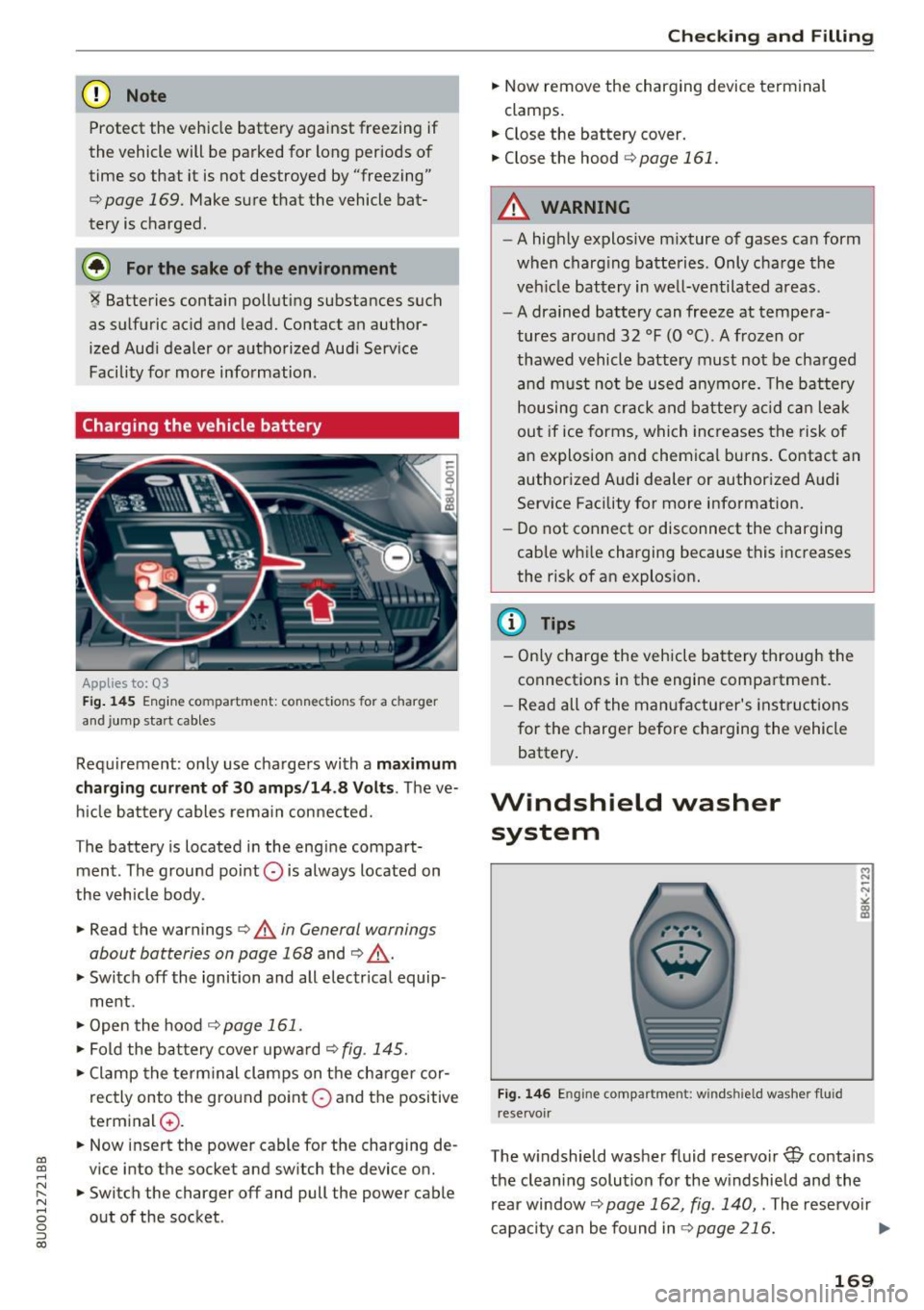
Fig. 145 Engine compartment: connections for a charg er
and jump start cables
Requirement : only use chargers with a maximum
charging current of 30 amps/14.8 Volts .
The ve
hicle battery cables remain connected.
The battery is located in the engine compart
ment. The ground point
0 is always located on
the vehicle body .
.,. Read the warnings
c;, .&. in General warnings
about batteries on page 168
and c;, .&, .
.,. Switch off the ignition and all electrical equip-
ment .
.,. Open the hood
c;, page 161 .
.,. Fold the battery cover upward c;, fig. 145 .
.,. Clamp the terminal clamps on the charger cor
rectly onto the ground point
0 and the positive
terminal
0 .
.,. Now insert the power cable for the charging de
vice into the socket and switch the device on.
.,. Switch the charger off and pull the power cable
out of the socket .
Checking and Filling
.,. Now remove the charging device terminal
clamps.
.,. Close the battery cover.
.,. Close the hood
c;, page 161.
A WARNING
-- A highly explosive mixture of gases can form
when charging batteries. Only charge the
veh icle battery in well-ventilated areas.
- A drained battery can freeze at tempera
tures around 32 °F (0 °C) . A frozen or
thawed vehicle battery must not be charged
and must not be used anymore . The battery
housing can crack and battery acid can leak
out if ice forms, which increases the risk of
an explosion and chemical burns. Contact an
authorized Audi dealer or authorized Audi
Service Facility for more information.
- Do not connect or disconnect the charging
cable while charging because this increases
the risk of an explosion.
@ Tips
- Only charge the vehicle battery through the
connections in the engine compartment.
- Read all of the manufacturer's instructions
for the charger before charging the vehicle
battery.
Windshield washer system
Fig. 146 Engine compar tmen t: win ds hiel d washer flu id
re servoir
M N
-N ~ (D a,
The windshield washer fluid reservoir W contains
the cleaning solution for the windshield and the rear window
c;, page 162, fig . 140, . The reservoir
capacity can be found in
c;,page 216. .,.
169
Page 185 of 236
00
00
......
"' ,....
"' ...... 0 0 :::,
00
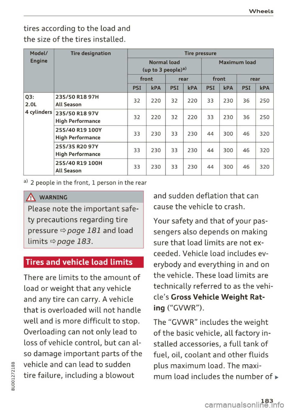
tires according to the load and
the size of the tires installed .
Model/
Tire designation
Engine
Wheels
Tire pressure
Normal load Maximum load
(up to 3 people)a>
front rear front rear
PSI
Q3: 235/50 Rl8 97H
32 2.0L All Season
4 cylinders 235/50 Rl8 97V
High Performance
32
255/40 Rl9 l00Y
33 High Performance
255/35 R20 97Y
33 High Performance
255/40 Rl9 l00H
33 All Season
a) 2 people in the front, 1 person in the rear
A WARNING
Please note the important safe
ty precautions regarding tire pressure
c:::> page 181 and load
limits
c:::> page 183.
Tires and vehicle load limits
There are limits to the amount of
load or weight that any vehicle
and any tire can carry. A vehicle
that is overloaded will not handle
well and is more difficult to stop.
Overloading can not only lead to
loss of vehicle control, but can al
so damage important parts of the
vehicle and can lead to sudden
tire failure, including a blowout
kPA PSI kPA PSI kPA PSI
220 32 220 33 230 36
220 32 220 33 230 36
23 0 33 230 44
300 4
6
230 33 230 44 300 46
23 0
33 230
44 3
00 4
6
and sudden deflation that can
cause the vehicle to crash.
kPA
250
250
320
320
3 20
Your safety and that of your pas
sengers also depends on making
sure that load limits are not ex
ceeded. Vehicle load includes ev
erybody and everything in and on
the vehicle . These load limits are
technically referred to as the vehi
cle's
Gross Vehicle Weight Rat
ing
("GVWR").
The "GVWR" includes the weight
of the basic vehicle, all factory in
stalled accessories, a full tank of
fuel, oil, coolant and other fluids
plus maximum load. The maxi
mum load includes the number of.,.
183
Page 199 of 236
a:,
a:,
...... N r--. N .-< 0 0 ::, a:,
Emergency assistance
General information
.. Park the vehicle as far as poss ible from moving
traffic in the event of a breakdown. In the event
of a flat tire, park the vehicle on a leve l surface .
It you are on a steep h ill, be especially careful.
.. Set the parking brake .
.. Switch the emergency flashe rs on .
.. Put on a reflective vest .
.. Set up the warn ing triang le, if available .
.. Have the passengers exi t the veh icle. They
sho uld move to a safe place, for example be
hind a guard rail.
_& WARNING
Follow the steps given above. This is for your
protection and the for the safety of other d riv
ers.
_& WARNING
Improper use of the vehicle jack can cause se
rious personal injuries .
- Never use the screw driver hex head to
t ighten whee l bolts, since the bolts cannot
attain the necessary tighten ing torque if you
use the hex head, potentially causing an ac
c ident .
- The factory-supplied jack is intended only
for your vehicle model. Under no circum
stances should it be used to lift heavy
vehicles o r other loads; yo u ris k inju ring
yo urself.
- Never start the engine when the vehicle is
ra ised, which could cause a n accident.
- Support the veh icle secure ly with app ropr i
a te s tan ds if wor k is to be performed under
neath t he vehicle; otherwise, the re is a po
tent ial ris k for i njur y.
- Never use the jack s upplied with yo ur Audi
on another vehicle, pa rtic ularly o n a heav ie r
one. The jack is only suitable for u se on the
vehicle it came wit h.
Emergen cy a ssis tanc e
Equipment
Vehicle tool kit
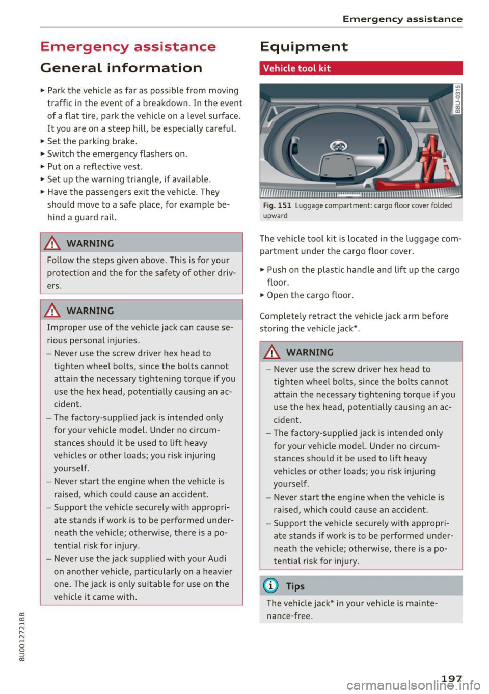
Fig. 151 Lu gg age compartmen t: cargo floo r cove r fo lded
u pwa rd
T he veh icle tool k it is located in the luggage com
partment under the cargo floor cover.
.. Push on the p lastic handle and lift up the cargo
floor .
.. Open the cargo floor.
Completely retract the veh icle jack a rm before
stor ing the ve hicle jack*.
_& WARNING
- Never use the screw driver hex head to
tighten wheel bo lts, since the bolts cannot
attain the necessary tightening torque if yo u
use the hex head, potentially causing an ac
cident.
- The factory-supp lied jack is intended only
for your ve hicle model. Under no circum
stances shou ld it be used to lift heavy
veh icles or other loads; you risk injuring
yourse lf.
- Never start the engine when the ve hicle is
raised, which could cause an accident.
- Support the vehicle securely with appropri
ate stands if wo rk is to be performed under
neath the vehicle; otherwise, there is a po
tential risk fo r injury .
@ Tips
The vehicle jack * in your vehicle is mainte
nance-free.
197
Page 203 of 236
a:,
a:,
...... N r-,. N
"" 0 0 ::, a:,
.. Install the rod on the vehicle jack: Insert the
rod into the opening on the handwheel. Turn
the rod left or r ight to secure it.
.. Cont inue raising the jack with the rod until the
wheel lifts off the ground slightly.
Position the vehicle jack
onl y under the designat
ed lifting points on the sill
c:::> fig. 156. There is ex
actly
one location for each wheel. The jack must
not be pos itioned at any other location
c:::> .&.,
c:::> CD.
Soft grou nd under the jack can cause the vehicle
to slip off the jack. Always place the jack on firm
ground . Use a flat, stable support if necessary.
Use a non-slip surface such as a rubber mat on a
s lipper y surfa ce such as tile .
_& WARNING
-
-Yo u or your passengers could be injured
wh ile chang ing a whee l if yo u do not follow
these safety precau tions:
- Position the veh icle jack only at the desig
nated lifting points and align the jack.
Otherw ise, the vehicle jack cou ld slip and
cause an injury if it does not have suffi
cient hold on the vehicle.
- Use on ly the jack* supplied with your vehi
cle to raise the vehicle.
If yo u use a jack
from a d ifferent vehicle, your veh icle may
slip off the jack -ris k of injury!
- Do not use the jack* supp lied with your ve
h icle to ra ise other veh icles, as these may
slip off the jack -ris k of injury!
- A soft or unstable s urface under the jack
may cause the vehicle to s lip off the jac k.
Always p rovide a firm base fo r the jack on
the ground . If necessary, use a sturdy
board underthejack .
- On hard, sl ippery surfa ce (such as tiles)
use a rubbe r mat or similar to prevent the
jack from slipp ing.
- T o help prevent injury to you rself and yo ur
passenge rs:
- Do not ra ise the vehicle unt il you are sure
the jack is securely engaged .
- Passengers must not remain in the vehicle
when it is jacked up.
Em ergen cy a ssis tanc e
-Make sure that passengers wait in a safe
place away from the vehicle and well away
from the road and traffic .
- Make sure jack position is correct, adjust
as necessary and then continue to raise
the jack.
- If work has to be done under the veh icle,
ensure that it is safely supported on suita
ble stands -risk of injury!
- Never start the engine when the vehicle is
on the jack -risk of acc ident!
(D Note
Do not lift the ve hicle by the s ill. Pos ition the
vehicle jack only at the des ignated lifting
po ints on the sill. Otherw ise, your veh icle will
be damaged.
Taking the wheel off/installing the spare
tire
Follow these instructions step-by-step for chang
ing the wheel.
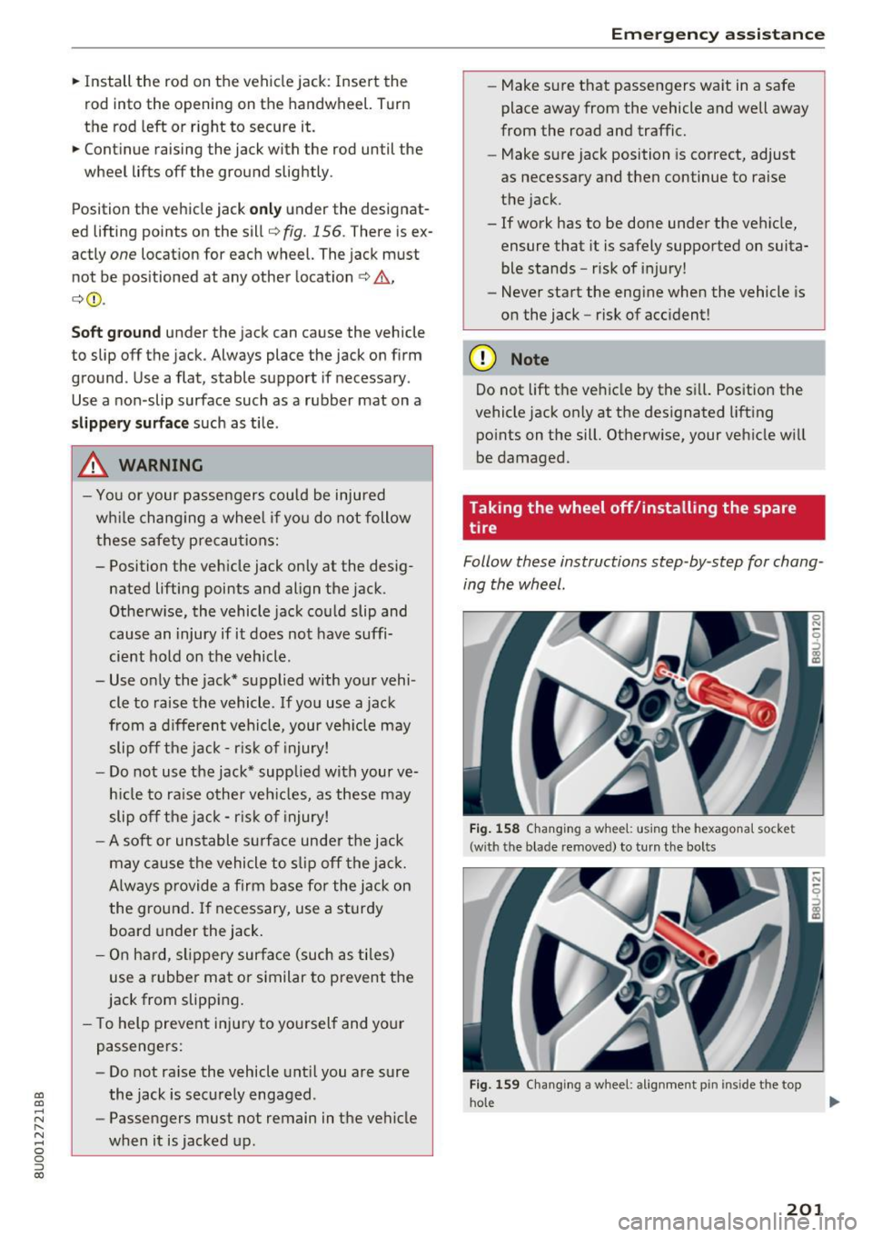
F ig . 1 58 Chang ing a w hee l: us ing the hexagona l socket
(with the blade removed) to turn the bolts
Fig. 159 Changi ng a whee l: alig nment p in i nside the top
h ole
201
Page 207 of 236
Fuses and bulbs
Electrical fuses
Replacing fuses
A fuse that has blown will have metal strips that
have burned through .
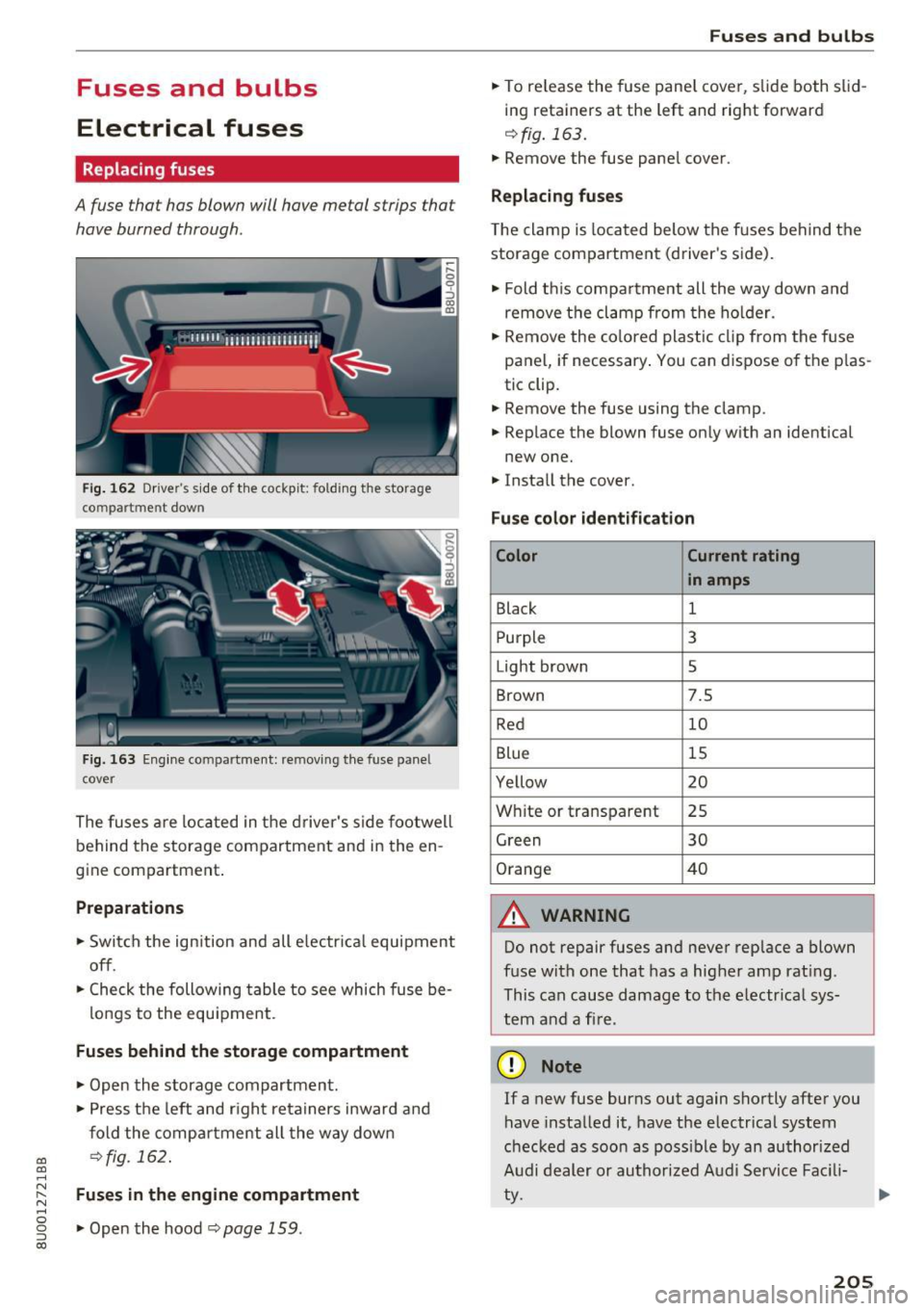
Fig. 162 Dr iver's side of th e cockpit: fold ing the storage
co mpartme nt down
Fig . 16 3 Engine compar tmen t: removing the fuse pane l
cover
The fuses are located in the driver 's side foo twell
be hind the storage compartment and in the en
g ine compartment .
Preparations
.. Switch the ign ition and all e lectr ica l equi pment
off.
.. Check the following table to see which fuse be -
l ongs to the equipment .
Fuses behind the storage compartment
.. Open the storage compartmen t.
.. Press t he left and r igh t re tainers inward and
fold the compartment all the way dow n
oo ¢fig. 162. a:, ...... N ~ Fuses in the engine compartment
'"' 0 g .. Open the hood ¢ page 159.
a:,
Fuses and bulbs
.. To re lease the fuse panel cove r, slide both s lid
ing retainers at the left and right forward
¢fig . 163 .
.. Remove the fuse panel cover.
Replacing fuses
T he clamp is loca ted below the f uses beh ind the
storage compartment (d river's side) .
.. Fold t his compa rtme nt all the way down a nd
remove t he cl amp from the ho lder .
.. Remove the co lored plas tic clip from the fuse
pane l, if necessary . You can d ispose o f the p las
tic clip .
.. Remove the fuse using the clamp .
.. Rep lace the blown fuse only with an identical
new one .
.. Insta ll the cover.
Fuse color identifi cation
Color Current rating
in amps
Black 1
P urple 3
Light brown 5
Brown 7.5
Red 10
Blue 15
Ye llow 20
W hite or transpa rent 25
Green 30
O range 40
A WARNING
Do not repair fuses and never rep lace a blown
f u se wit h one that has a hig her amp rat ing .
This can cause damage to the e lectr ica l sys
tem and a fir e.
(D Note
If a new fuse burns out again shortly after you
have insta lled it, have the electrical system
checked as soon as poss ible by an author ized
A udi dealer or au tho rized Aud i Service Fac ili
ty.
205
Page 208 of 236
Fuses and bulbs
(D Tips
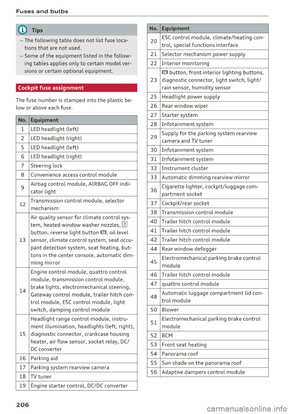
- The following table does not list fuse loca
tions that are not used.
- Some of the equipment listed in the follow
ing tables applies only to certain model ver
sions or certain optional equipment.
Cockpit fuse assignment
The fuse number is stamped into the plastic be
low or above each fuse.
No. Equipment
1 LED headlight (left)
2 LED headlight ( right)
5 LED headlight (left)
6 LED headlight (right)
7 Steering lock
8 Convenience access contro l module
9
Airbag control module, AIRBAG OFF indi-
cator light
12
Transmission control module, selector
mechanism
Air quality sensor for cl imate control sys-
tern, heated w indow washer nozzles ,
lj]
button, reverse light button<®>, oi l level
13 sensor, climate contro l system, seat occu-
pant detection system, seat heating, but-
tons in the center console, automatic dim-
ming mirror
Engine control module, quattro control
modu le, transmission control module,
14
brake lights, electromechanica l steering,
Gateway control module, trai ler hitch con-
trol module, ESC contro l module, light
switch, damping control module
Headlight range control module , instru-
ment illumination, headlights (left, right),
15 diagnostic connector, crankcase housing
heater, a ir flow sensor, socket relay, DC/
DC converter
16 Park ing aid
17 Parking system rearview camera
18 TV tuner
19 Engine starter control, DC/DC converter
206
No . Equipment
20
ESC contro l module, climate/heating con-
trol, special functions interface
21 Selector mechanism power supply
22 Interior monitoring
© button, front interior lighting buttons,
23 diagnostic connector, light switch, light/
rain sensor, humidity sensor
25 Headlight power supply
26 Rear window wiper
27 Starter system
28 Infotainment system
29
Supply for the parking system rearv iew
camera and TV tuner
30 Infotainment system
31 Infotainment system
32 Instrument cluster
33 A utomat ic dimming rearview mirror
36
Cigarette lighter, cockpit/luggage com-
partment socket
37 Cockpit/rear socket
38 Transmission control module
40 Trailer hitch control module
41 Tra iler hitch control module
42 Trailer hitch control module
44 Rear window defogger
45
Electromechanical parking brake control
module
46 Trailer hitch control module
47 quattro control module
48 Aut omat ic lu ggage compartment lid con-
tro l module
so Blower
51
Electromechanical parking brake control
module
52 BCM
53 Fr ont seat heating
54 Panorama roof
SS Sun shade on the panorama
roof
56 Adaptive dampers control module
Page 209 of 236
00
00
......
"' ,....
"' ...... 0 0 :::,
00
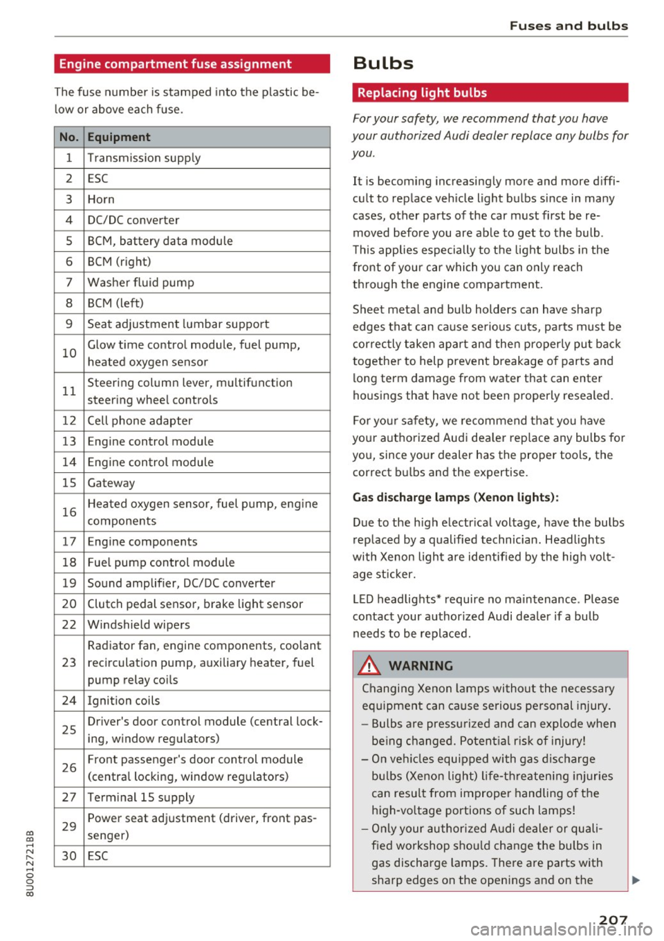
Engine compartment fuse assignment
The fuse number is stamped into the plastic be
low or above each fuse.
No. Equipment
1 Transmiss ion supply
2 ESC
3 Horn
4 DC/DC
converter
5 BCM, battery data module
6 BCM (right)
7 Washer fluid pump
8 BCM (left)
9 Seat adjustment lumbar support
10 Glow time
control module, fuel pump,
heated oxygen sensor
11 Steering
column lever, multifunction
steer ing whee l controls
1 2 Cell phone adapter
13 En
gine control module
14 Engine control module
15 Gateway
16 Heated oxygen sensor, fuel pump, eng
ine
components
17 Engine components
18 Fue
l pump control module
19 Sound amplifier, DC/DC converter
20 Clutch pedal sensor, brake light sensor
22 Windshield wipers Radiator fan, engine components, coolant
23 recirculation pump, auxiliary
heater, fuel
pump relay coils
24 Ignition coils
25 Driver's door
control module (central lock-
ing, window regulators)
26 Front passenger's door control module
(centra
l locking, window regulators)
27 Term inal 15 supply
29 Power seat adjustment (driver,
front pas-
senger)
30 ESC
Fu ses an d bulb s
Bulbs
Replacing light bulbs
For your safety, we recommend that you have
your authorized Audi dealer replace any bulbs for
you .
It is becoming increasingly more and more diffi
cult to replace vehicle light bulbs since in many
cases, other parts of the car must first be re
moved before you are able to get to the bulb .
T his applies especially to the light bulbs in the
front of your car which you can only reach
through the engine compartment .
Sheet metal and bu lb holders can have sharp
edges that can cause serious cuts, pa rts must be
correctly taken apart and then properly put back
together to help prevent breakage o f parts and
long term damage from water that can enter
housings that have not been properly resealed.
For your safety, we recommend that you have
your authorized Aud i dea ler rep lace any bulbs fo r
you, since your dealer has the proper tools, the
correct bulbs and the expertise.
Gas di schar ge la mps (Xe no n ligh ts):
Due to the high electr ical voltage, have the bulbs
rep laced by a qualified technician. Headlights
with Xenon light are identified by the hig h volt
age st icker.
LED headlights* require no maintenance . Please
contact your authorized Audi dea ler if a bulb
needs to be replaced.
_&. WARNING
Changing Xenon lamps wi thout the necessary
equipment can cause serious personal injury .
- Bulbs are pressu rized and can explode when
be ing changed. Potent ial ris k of injury!
- On veh icles equipped with gas disc harge
bu lbs (Xenon light) life-threatening injuries
can resu lt from improper handling of the
high-vo ltage portions of such lamps!
- Only your authorized A udi dealer or quali
f ied workshop sho uld change the bulbs in
gas discharge lamps. There are parts with
sharp edges on the openings and on the
207