load capacity AUDI Q3 2018 Owners Manual
[x] Cancel search | Manufacturer: AUDI, Model Year: 2018, Model line: Q3, Model: AUDI Q3 2018Pages: 230, PDF Size: 57.03 MB
Page 11 of 230

a
co
...... N r--. N .-< 0 0 ::, co
high outside temperatures and heavy en
gine load .
- The front spoiler also he lps to distribute
cooling air correctly while driving. If the
spoiler is damaged, the cooling effect will
be impaired and the risk of the engine over
heating will increase. See an authorized
Audi dealer or authorized Audi Service Fa
cility for assistance.
Tachometer
The tachometer displays the engine speed in rev
olutions per minute (RPM) .
You should shift to the next lowest gear when
the engine speed is below 1,SOO RPM . The begin
ning of the red zone in the tachometer indicates
the maximum permissible engine speed for all
gears once the engine has been broken in and
when it is warmed up to operating temperat ure.
Before reaching the red zone, you shou ld shift in
to the next higher gear, choose the Dor S selec
tor lever position, or remove your foot from the
accelerator pedal.
CD Note
The needle in the tachometer @Q page 8,
fig. 3 may only be in the red area of the gauge
for a short time or there is a risk of engine
damage.
@ For the sake of the environment
Upshifting ea rly helps you to save fuel and re
duces operating noise.
Fuel level
The fuel level indicator only operates when the
ignition is switched on.
The
tD ¢ page 15 turns on if the reserve quan
tity of fue l is reached.
The fuel tank capacity of your vehicle is listed in
the
Technical Data section ¢ page 210.
CD Note
Never drive until the tank is completely emp
ty. The irregular supply of fuel that results
Instruments and indicator lights
from that can cause engine misfires . Uncom
busted fuel will then enter the exhaust sys
tem. This can cause overheat ing and damage
to the catalytic converter.
Odometer
Fig. 4 I n st ru me nt cluster : odometer
Trip odometer and odometer
The trip odometer @ shows the distance driven
since it was last reset. It can be used to measure
short distances.
T he trip odometer can be reset to zero by press
ing the
10.01 reset button @~ page 8, fig. 3.
The odometer @shows the total distance that
the vehicle has been driven.
Malfunction indicator
If there is a malfunction in the instrument clus
ter,
DEF will appear in the trip odometer display.
Have the malfunction corrected as soon as possi
ble.
Time/date display
You can switch between the quartz clock or the
GPS controlled clock* depending on the vehicle
equipment. For more information, refer to your
MMI Operating Manual.
Outside temperature display
The instrument cluster display shows the outside
temperature. At temperatures below 42 °F ( +S
°C), a snowflake symbol appears in front of the
temperature display . .,.
9
Page 75 of 230
0 co ......
"' ,-...
"' ...... 0 0 :::,
00
Trailer towing
Driving with a trailer
General information
Your vehicle is primarily intended for transport ing people and luggage . However, if you drive
with a trailer , follow the technical requirements,
the operation and driving tips, and the legal reg
ulations.
Driving with a trailer affects the vehicle's fuel
consumption, performance and wear.
It also re
quires higher concentration from the driver.
A WARNING
Do not transport any people in a trailer due to
the risk of fatal injury.
Technical requirements
Certain requirements must be met when towing
a trailer.
Trailer hitch
Only use a trailer hitch with a removable ball hitch mount and ball hitch. The trailer hitch must
be permitted for the vehicle , the trailer and the
permitted total weight of the trailer being
pulled. Above all, it must be securely and safely
attached to the vehicle trailer.
Never mount a trailer hitch on the bumper. The
trailer hitch must be mounted in a way that does
not impair the function of the bumper. Do not
make any changes to the exhaust system and the
brake system.
Check regularly if the trailer hitch is securely mounted. Always follow the instructions given by
the trailer hitch manufacturer.
Trailer brakes
If the trailer has its own brake system, then fol
low the manufacturer specifications. However,
the brake system on the trailer must never be
connected to the vehicle brake system.
Trailer towing
Engine cooling system
Driving with a trailer means a higher load on the
engine and the cooling system. The cooling sys
tem must be designed for additional load and
contain enough coolant
c::> (D .
A WARNING
-
-Never mount a "weight-distributing" or
"load-balancing" trailer coupler as the trail
er hitch . The vehicle was not designed for
these types of trailer hitches . The trailer
hitch can malfunction and the trailer can
break off from the vehicle.
- If the trailer is equipped with electronic
brakes, these brakes cannot be activated by
a factory-installed control system, which in
creases the risk of an accident.
- To reduce the risk of injury, always remove
the ball hitch mount if no trailer is mount
ed.
(D Note
Longer inclines cannot be driven without a
suitable cooling system, especially if the out
side temperatures are high. otherwise, this
increases the risk of engine damage.
' Operating instructions
Several things must be noted when towing a
trailer.
Towing capacity
The permitted towing capacity for trailers with
out brakes is 1,650 lbs (750 kg).
The permitted towing capacity for trailers with brakes is 2,200 lbs (1,000 kg) .
These values apply to roads with up to 12% in
cline.
Tongue weight
The maximum permitted tongue weight of the
trailer drawbar on the trailer hitch ball head may
not be exceeded. ..,.
73
Page 169 of 230
a
co
...... N r--. N
'"' 0 0 ::, co
Tire designations
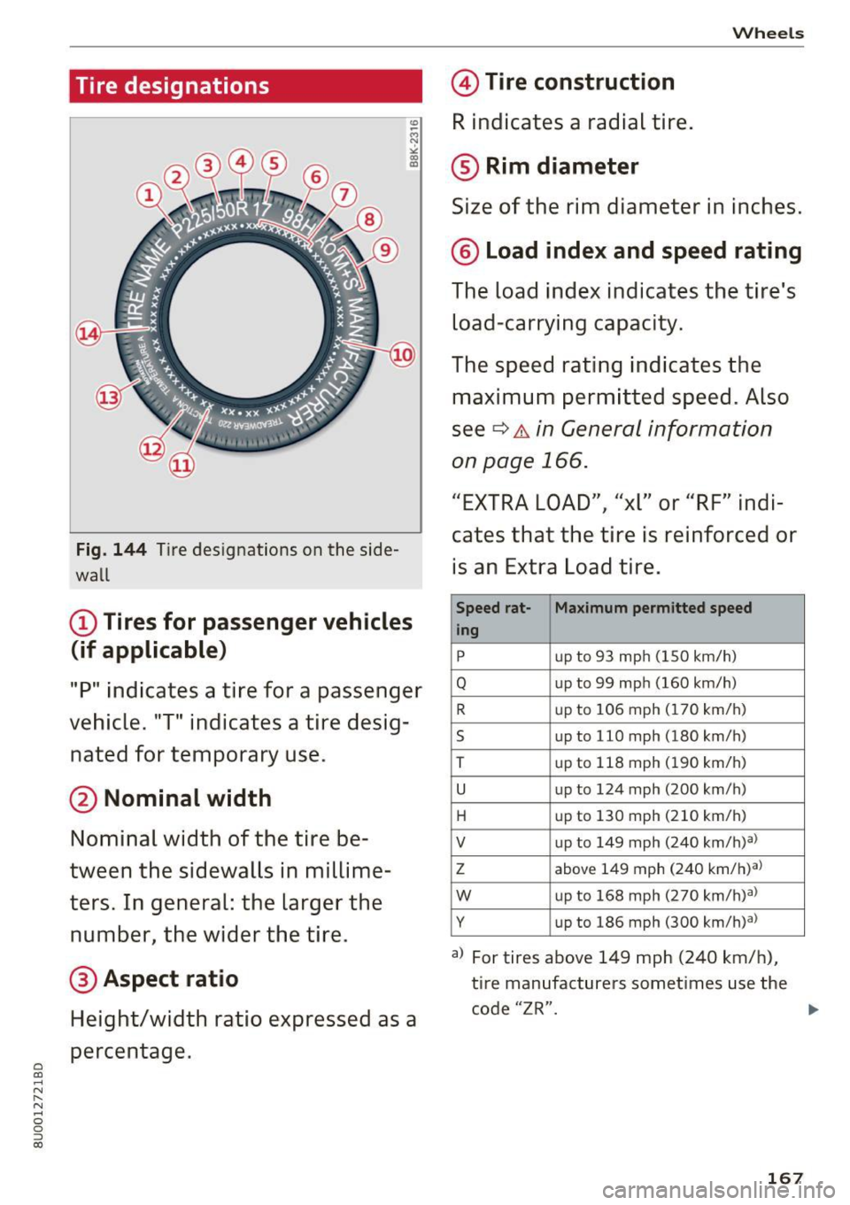
Fig. 144 Tire designations on the side
wall
(D Tires for passenger vehicles
(if applicable)
"P" indicates a tire for a passenger
vehicle. "T" indicates a tire desig
nated for temporary use.
@ Nominal width
Nominal width of the tire be
tween the sidewalls in millime
ters. In general: the larger the number, the wider the tire.
@ Aspect ratio
Height/width ratio expressed as a
percentage .
Wheels
© Tire construction
R indicates a radial tire.
® Rim diameter
Size of the rim diameter in inches.
@ Load index and speed rating
The load index indicates the tire's
load-carrying capacity.
The speed rating indicates the
maximum permitted speed. Also
see
¢ &. in General information
on page 166.
"EXTRA LOAD", "xl" or "RF" indi
cates that the tire is reinforced or
i s an Extra Load tire.
Speed rat-
Maximum permitted speed
ing
p up to 93 mph (150 km/h)
Q up to 99 mph (160 km/h)
R up to 106 mph (170 km/h)
s up to 110 mph (180 km/h)
T up
to 118 mph (190 km/h)
u up to 124 mph (200 km/h)
H up
to 130 mph (210 km/h)
V up
to 149 mph (240 km/h?)
z above 149 mph (240 km/h)a)
w up to 168 mph (270 km/h)a)
y up to 186 mph (300 km/h)a)
a) For tires above 149 mph (240 km/h),
tire manufacturers sometimes use the
code "ZR".
167
Page 171 of 230
0 C0
-N
" N
-0 g a)
Glossary of tire and loading
terminology
Accessory weight
means the combined we ight (in
excess of those standard items
which may be replaced) of auto matic transmission, power steer
ing, power brakes, power win
dows, power seats, radio, and
heater, to the extent that these
items a re available as factory- in
stalled equipment (whether in
stalled or not) .
Aspect ratio
means the ratio of the height to
the width o f the tire in percent .
Numbers of 55 or lower indicate a
low s idewal l for improved steer
ing response and better overall
handling on dry pavement.
Bead
means the part of the t ire that is
made of steel wires, wrapped or
reinforced by ply cords and that is
shaped to fit the rim .
Bead separation
means a breakdown of the bond
between components in the bead .
Wheels
Cord
means the strands forming the
plies in the tire.
Cold tire inflation pressure
means the tir e pressure recom
mended by the vehicle manufac
tu rer for a tire of a designated
size that has not been driven for
more than a couple of m iles (k ilo
meters) at low speeds in the
three hour period before the t ire
pressure is measured or adjusted .
Curb weight
means the weight of a motor ve
hicle with standard equipment in
cluding the maximum capacity of
f u el, o il, and coolant, a ir cond i
tioning and additional weight of
optio nal eq uipment .
Extra load tire
means a tire designed to operate
at higher loads and at higher in
flat ion pressu res than the corre
sponding standard tire . Extra load
tires may be ident ified as "X L",
"xl", "EXTRA LOAD", or "RF" on
the sidewall. .,.
169
Page 172 of 230
Wheel s
Gross Axle Weight Rating
("GAWR ")
means the load-carrying capacity
of a single axle system , measured
at the tire -ground interfaces.
Gross Veh icle Weight Rating
(" GVWR ")
means the maximum total loaded
weight of the vehicle .
Groove
means the space between two ad
jacent tread ribs .
Load rating (code )
means the maximum load that a
tire is rated to carry for a given in
flation pressure. You may not find
this information on all tires be
cause it is not required by law.
Ma ximum load rating
means the load rating for a tire at
the maximum permissible infla
tion pressure for that tire.
Ma ximum loaded veh icle
weight
means the sum of:
(a) Curb weight
(b) Accessory weight
(c) Vehicle capacity weight, and
(d) Production options weight
170
Ma ximum (permissible)
inflation pressu re
means the maximum cold infla
tion pressure to which a tire may be inflated. A lso called "maxi
mum inflation pressure."
Normal occupant weight
means 150 lbs. (68 kilograms)
times the number of occupants seated in the vehicle up to the to
tal seating capacity of your vehi
cle.
Occupant d istribution
means distr ibution of occupants
in a vehicle.
Outer d iameter
means the overall diameter of an
inflated new tire.
Overall width
means the linear distance be
tween the exteriors of the side
walls of an inflated tire, includ ing
elevations due to labeling, deco rations, or protective bands or
ribs .
Ply
means a layer of rubber-coated
parallel cords.
Page 175 of 230

0 C0
-N
" N
-0
0
::, a)
by the tire manufacturer. This in
formation is used to contact con
sumers if a tire defect requires a
recall.
Ve hicle capacity weight
means the rated cargo and lug
gage load plus 150 lbs. (68 k ilo
grams) times the vehicle's desig
nated seating capacity.
Vehicle ma ximum load on the
tire
means that load on an individual
tire that is determined by distrib
uting to each axle its share of the
maximum loaded vehicle weight
and dividing by two.
Vehicle normal load on the tire
means that load on an individual
tire that is determined by distrib
uting to each axle its share of the
curb weight, accessory weight,
and normal occupant weight (dis
tributed in accordance with¢
ta
ble on page
178) and dividing by
two.
Occupant loading and distr i
bution for vehicle normal load
for various design ated seating
capacities
Refer to the tire inflation pres
sure label¢
page 176, fig. 147
Wheels
for the number of seating posi
tions . Refer to the table ¢
table
on page
178 for the number of
people that correspond to the ve
hicle normal load.
New tires or wheels
Audi recommends having all work
on tires or wheels performed by an authorized Audi dealer or au
thorized Audi Service Facility.
These facilities have the proper
knowledge and are equipped with
the required tools and replace ment parts.
.,,. New tires do not yet have the
optimum gripp ing properties .
Drive carefully and at moderate
speeds for the first 350 miles (500 km) with new tires.
.,,. Only use tires with the same de
sign, size (rolling circumference)
and as close to the same tread
pattern as possible on all four
wheels.
.,,. Do not replace tires individually .
At least replace both tires on the
same axle at the same time.
.,,. Audi recommends that you use
Audi Original Tires . If you would
like to use different tires, please note that the tires may perform ...
173
Page 182 of 230
Wheels
Determining correct load
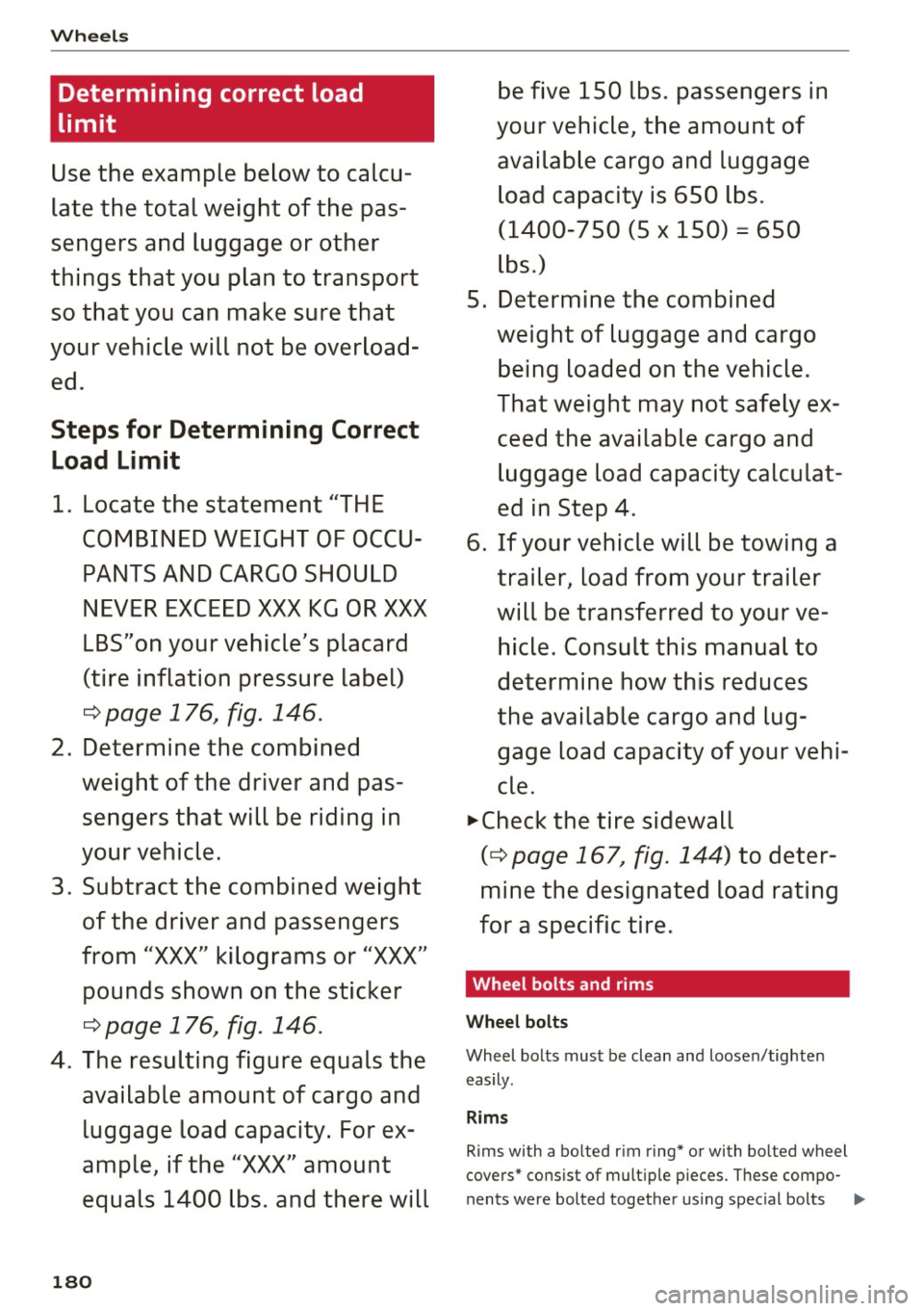
limit
Use the example below to calcu
late the total weight of the pas
sengers and luggage or other
things that you plan to transport so that you can make sure that
your vehicle will not be overload ed .
Steps for Determining Correct
Load Limit
1 . Locate the statement "THE
COMBINED WEIGHT OF OCCU PANTS AND CARGO SHOULD
NEVER EXCEED XXX KG OR XXX
LBS"on your vehicle 's placard
(tire inflation pre ssure label)
c:::> page 176, fig. 146.
2. Determine the combined
weight of the driver and pas
sengers that will be riding in
your vehicle.
3 . Subtra ct the combined weight
of the driver and passengers
from
"XXX" kilograms or " XXX"
pounds shown on the sticker
c:::> page 176 , fig. 146 .
4. The re sulting figure equals the
available amount of cargo and luggage load capacity. For ex
ample, if the
"XXX" amount
equals 1400 lbs. and there will
180
be five 150 lbs. passengers in
your vehicle, the amount of available cargo and luggage load capacity is 650 lb s.
(1400-750 (5 X 150) = 650
lb s.)
5. Determine the combined weight of luggage and cargo
being loaded on the vehicle.
That weight may not safely ex
ceed the available cargo and luggage load capacity calculat
ed in Step 4 .
6. If your vehicle will be towing a trailer, load from your trailer
will be transferred to your ve
hicle. Con sult this manual to
determine how this reduces
the available cargo and lug gage load capacity of your vehi
cle .
~check the tire sidewall
(c:::> page 167, fig. 144) to deter
mine the designated load rating
for a specific tire.
· Wheel bolts and rims
Wheel bolts
W heel bolts mus t be clean and loose n/tighten
eas ily.
Rims
R ims with a bo lted r im ring * or with bo lted wheel
covers" co nsist of mult ip le p ieces . T h ese compo-
n ents were bolted togethe r usin g s pec ial bolts ..,.
Page 212 of 230
Tech nical data
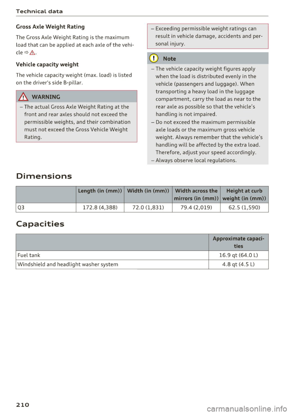
Gross Axle Weight Rating
The G ross Ax le We ight Rating is the max imum
load that can be applied at each axle of the vehi
cle ¢& .
Vehicle capacity weight
The vehicle capacity we ight (max. load) is l isted
on the d river's side 8-p illar.
_& WARNING
- T he ac tual Gross Axle Weight Rating a t the
front and rear axles sho uld not exceed the
permissible weights, and their combination
must not exceed the Gross Veh icle Weight
Rating.
Dimensions
- Exceed ing permissible weight ratings can
result in vehicle damage, accidents and per
sonal injury.
(D Note
- The vehicle capacity weight figures apply
when the load is d istr ibuted evenly in the
vehicle (passengers and luggage). When
t ransporting a heavy load in the luggage
compartment, carry the load as near to the
rea r axle as possib le so that the vehicle's
hand ling is not impaired .
- Do not exceed the max imum perm iss ible
axle loads or the maximum gross vehicle
we ight. Always remember that the ve hicle's
han dling will be affe cted by the extra load.
T herefore, a djust your speed acco rd ingly.
- Always observe lo cal regulations.
length (in (mm )) Width (in (mm )) Width across the Height at curb
mirrors (in (mm )) weight (in (mm))
Q3 172.8 (4,388) 72.0 ( 1,83 1) 79.4 (2,019) 62.5 (1,590)
Capacities
Approximate capaci-
ties
Fuel tank 16.9 qt (64 .0 L)
Winds hield and headlight washe r system 4
.8 qt (4.5 L)
210
Page 222 of 230
Index
Current consumption . . . . . . . . . . . . . . . . . . 19
Fuel gauge . . . . . . . . . . . . . . . . . . . . . . . . . 8, 9
Fuel tank capacity ................... 210
Gasoline . . . . . . . . . . . . . . . . . . . . . . . . . . . 152
Gasoline additives . . . . . . . . . . . . . . . . . . . 153
Saving fuel . . . . . . . . . . . . . . . . . . . . . . . 57, 81
Fuel economy messages (efficiency program) .21
Fueling Fuel filler door emergency release . . . . . . 155
F uel gauge . . . . . . . . . . . . . . . . . . . . . . . . . . . 9
F uel tank capacity . . . . . . . . . . . . . . . . . . . 210
Opening the fuel filler door . . . . . . . . . . . . 153
Fuses . . . . . . . . . . . . . . . . . . . . . . . . . . . . . . . 199
G
Garment hooks . . . . . . . . . . . . . . . . . . . . . . . . 46
Gas discharge lamps . . . . . . . . . . . . . . . . . . . 201
Gasoline . . . . . . . . . . . . . . . . . . . . . . . . . . . . 152
Octane rating . . . . . . . . . . . . . . . . . . . . . . . 152
Recommendation . . . . . . . . . . . . . . . . . . . . 152
Generator (indicator light) . . . . . . . . . . . . . . . 13
Glossary of tire and loading terminology . . 169
Glove compartment . . . . . . . . . . . . . . . . . . . . 45
Gross Vehicle Weight Rating (GVWR) . . . . . 209
Ground clearance . . . . . . . . . . . . . . . . . . . . . . 66
H
Headlight range control . . . . . . . . . . . . . . . . . 33
Headlights Cleaning . . . . . . . . . . . . . . . . . . . . . . . . . . . 186
H eadlight range control . . . . . . . . . . . . . . . 33
Head restraints . . . . . . . . . . . . . . . . . . . . . . . 100
Adjusting .. .. ................ 43, 44, 100
Removing and installing . . . . . . . . . . . . . . . 44
Heated Exterior mirrors . . . . . . . . . . . . . . . . . . . . . . 36
Rear window (automatic climate control sys-
tem) . . . . . . . . . . . . . . . . . . . . . . . . . . . . . . . 55
Rear window (manual climate control sys -
tem) . . . . . . . . . . . . . . . . . . . . . . . . . . . . . . . 53
Seats (automatic climate control system) . 55
Washer nozzles . . . . . . . . . . . . . . . . . . . . . . 38
Heavy clothing and safety belts . . . . . . . . . . 108
High beams . . . . . . . . . . . . . . . . . . . . . . . . . . . 34
Hill descent assist ... . .. .. ...... .. .. .. .. 91
Hill descent control . . . . . . . . . . . . . . . . . . . . 70
220
Hill hold assist . . . . . . . . . . . . . . . . . . . . . . . . 65
also refer to Hill hold assist . . . . . . . . . . . . 65
Hold ass ist (hill) . . . . . . . . . . . . . . . . . . . . . . . 65
Horn . . . . . . . . . . . . . . . . . . . . . . . . . . . . . . . . . 6
How are child restraint system anchors relat-
ed to child safety . . . . . . . . . . . . . . . . . . . . . 147
How many a irbags does my vehicle have? . . 120
How safety belt pretensioners work 112
I
Ignition
Switching on and off (convenience key) . . . 61
Switching on and off (ignition lock) . . . . . . 60
Imbalance (wheels) . . . . . . . . . . . . . . . . . . . 175
Immobilizer . . . . . . . . . . . . . . . . . . . . . . . . . . 23
Important things to do before driving . . . . . 97
Improperly worn safety belts . . . . . . . . . . . 112
Indicator lights . . . . . . . . . . . . . . . . . . . . . . . . 10
Airbag system . . . . . . . . . . . . . . . . . . 124, 125
PASSENGER AIR BAG OFF . . . . . . . . . . . . . 125
Infant seats . . . . . . . . . . . . . . . . . . . . . . . . . 140
Inspection interval . . . . . . . . . . . . . . . . . . . . 165
Installing child safety seats Safety belts . . . . . . . . . . . . . . . . . . . . . . . . 144
Installing the upper tether strap on the an
chorage . . . . . . . . . . . . . . . . . . . . . . . . . . . . . 150
Instrument cluster . . . . . . . . . . . . . . . . . . . . . . 8
Cleaning . . . . . . . . . . . . . . . . . . . . . . . . . . . 187
Instruments . . . . . . . . . . . . . . . . . . . . . . . . . . . 8
Adjusting the lighting . . . . . . . . . . . . . . . . . 35
Interior lighting . . . . . . . . . . . . . . . . . . . . . . . 35
Interior lighting . . . . . . . . . . . . . . . . . . . . . . 35
Interval mode (windshield wipers) . . . . . . . . 38
J
Jack . . . . . . . . . . . . . . . . . . . . . . . . . . . . . . . . 194
Jump-starting . . . . . . . . . . . . . . . . . . . . . . . . 203
Jumper cables . . . . . . . . . . . . . . . . . . . . . . . . 204
K
Key........ .. .. .. .. .. ... .......... ... 23
Key not recognized . . . . . . . . . . . . . . . . . . . 63
Key recognition . . . . . . . . . . . . . . . . . . . . . . 51
Key replacement . . . . . . . . . . . . . . . . . . . . . 23
Replacing the battery . . . . . . . . . . . . . . . . . 23
Page 225 of 230
Safety belt pretensioner Service and disposa l............ ..... . 113
Safety belts . . . . . . . . . . . . . . . . . . . . . . 106, 109
C leaning . . . . . . . . . . . . . . . . . . . . . . . . . . . 187
Danger to passengers who do not wear a
safety belt . . . . . . . . . . . . . . . . . . . . . . . . . 107
Fastening . . . . . . . . . . . . . . . . . . . . . . . . . . 109
H eight adjustment . . . . . . . . . . . . . . . . . . . 111
Improperly worn ............. .. ..... 112
Not worn . . . . . . . . . . . . . . . . . . . . . . . . . . 107
Safety belt position . . . . . . . . . . . . . . . . . . 110
Safety instructions . . . . . . . . . . . . . . . . . . . 108
Securing child safety seats . . . . . . . . . . . . 144
Special considerations for pregnant wom-
en . . . . . . . . . . . . . . . . . . . . . . . . . . . . . . . . 111
Unfastening . . . . . . . . . . . . . . . . . . . . . . . . 111
Warning/indicator light . . . . . . . . . . . . . . 106
Worn properly . . . . . . . . . . . . . . . . . . . . . . 108
Safety instructions
for side curta in a irbags . . . . . . . . . . . . . . . 133
for using ch ild safety seats . . . . . . . . . . . . 137
for using safety be lts . . . . . . . . . . . . . . . . . 108
Monitoring the Advanced Airbag System . 126
Safety systems . . . . . . . . . . . . . . . . . . . . . . . . 14
Seat Number of seats
Seat adjustment 106
Head restraints . . . . . . . . . . . . . . . . . . . . . 100
Seat belts
refer to Safety belts . . . . . . . . . . . . . . . . . . 106
Seat heating Automatic climate control system . . . . . . . 55
Manual climate control system . . . . . . . . . . 53
Seating capacity . . . . . . . . . . . . . . . . . . . . . . 106
Seating position Driver . . . . . . . . . . . . . . . . . . . . . . . . . . . . . . 98
Fr ont passenger . . . . . . . . . . . . . . . . . . . . . .
99
How to adjust the front seats . . . . . . . . . . . 99
Incorrect seat position . . . . . . . . . . . . . . . 100
Occupants . . . . . . . . . . . . . . . . . . . . . . . . . . . 98
Rear passengers . . . . . . . . . . . . . . . . . . . . . .
99
Seats
Adjusting . . . . . . . . . . . . . . . . . . . . . . . . . . . 42
Cleaning . . . . . . . . . . . . . . . . . . . . . . . . . . . 188
~ Correct seating position . . . . . . . . . . . . . . . 98 ......
~ Folding . . . . . . . . . . . . . . . . . . . . . . . . . . . . . 47
N
8 Selective whee l torque contro l . . . . . . . . . . . 89
0
:::,
00
Index
Se lector lever (automatic transmission)
Emergency operation . . . . . . . . . . . . . . . . . . 72
Pos ition . . . . . . . . . . . . . . . . . . . . . . . . . . . . 67
Service and disposal Safety belt pretensioner . . . . . . . . . . . . . . 113
Service interval display . . . . . . . . . . . . . . . . . 165
Service position
refer to Replacing wiper blades . . . . . . . . . 39
Setting the temperature
Automatic climate cont rol system . . . . . . . 54
Sh ift paddles (automatic transm iss ion) . . . . 70
Side airbags Description . . . . . . . . . . . . . . . . . . . . . . . . . 128
How they work . . . . . . . . . . . . . . . . . . . . . . 129
Side assist
refer to Audi side assist . . . . . . . . . . . . . . . . 78
S ide curta in airbags . . . . . . . . . . . . . . . . . . . 131
Description . . . . . . . . . . . . . . . . . . . . . . . . . 131
How they work . . . . . . . . . . . . . . . . . . . . . . 132
Safety instructions . . . . . . . . . . . . . . . . . . . 133
Ski bag. ........... .... ........... .... 48
Snow chains . . . . . . . . . . . . . . . . . . . . . . . . . 181
Sockets . . . . . . . . . . . . . . . . . . . . . . . . . . . . . . 44
Sources of information about child restraints
and their use . . . . . . . . . . . . . . . . . . . . . . . . . 151
Space-saving spare tire (compact spare tire)
. 197
Spare tire . . . . . . . . . . . . . . . . . . . . . . . . . . . 197
Speedometer . . . . . . . . . . . . . . . . . . . . . . . . . . 8
Speed warning system . . . . . . . . . . . . . . . . . . 76
Stab ilization control
refer to E lectronic stabi lization control . . . 89
START ENGINE STOP button . . . . . . . . . . . . . 61
Starting (engine) . . . . . . . . . . . . . . . . . . . 60, 61
Steering Electromechanical steering . . . . . . . . . . . . . 93
Locking (convenience key) . . . . . . . . . . . . . . 62
Locking (ignition lock) . . . . . . . . . . . . . . . . . 60
also refer to Electromechanical steering 93
Steering wheel Adjusting . . . . . . . . . . . . . . . . . . . . . . . . . . . 59
Shift paddles (automatic transmiss ion) . . . 70
Steps for determining correct load limit . . . 180
Stopping (engine) . . . . . . . . . . . . . . . . . . . 60, 62
Storage compartments . . . . . . . . . . . . . . . . . 45
Subwoofer. . . . . . . . . . . . . . . . . . . . . . . . . . . 198
223