hood release AUDI Q5 2014 Owners Manual
[x] Cancel search | Manufacturer: AUDI, Model Year: 2014, Model line: Q5, Model: AUDI Q5 2014Pages: 316, PDF Size: 78.41 MB
Page 11 of 316
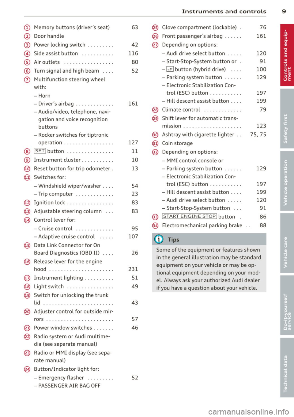
(!) Memory buttons (driver's seat)
@ Door handle
@ Power locking switch ........ .
© Side assist button ....... ... .
® A ir outlets .... .. ... ... .. .. .
@ Tu rn signa l and high beam . .. .
(j) Multifunction steering wheel
with:
- Horn
- Driver's airbag ............ .
- Audio/video, telephone, navi-
gation and vo ice recognition
buttons
- Rocker switches for tiptron ic
operation ................ .
@ ISETI button ... ..... ... ... . .
® Instrument cluster .......... .
@ Reset button for trip odometer .
@ Switches for:
- Windsh ield wiper/washer . .. .
- Trip computer ............ .
@ Ign ition lock ............... .
@ Adjustable steering column
€3J Control lever for:
- Cru ise contro l ........ .. .. .
- Adaptive cruise contro l .. .. .
@ Data Link Connector for On
Board Diagnostics (OBD II) . .. .
@ Release lever for the engine
hood .. .. .... ............. .
@ Instrument lighting .. ... .. .. .
@ Light switch ... .. ... ... .. .. .
@ Sw itch for un loc king the trunk
lid .... .. .. .... .. .... ... .. .
@ Adjuster control for outside mir-
63
42
116
80
52
16 1
127
11
10
13
54
23
83
83
95
107
26
23 1
51
49
43
rors . . . . . . . . . . . . . . . . . . . . . . . 57
@ Power wi ndow switches . . . . . . . 46
@ Radio system or Audi mu ltime-
d ia (see separate manual)
@ Radio or M MI display (see sepa
rate manual)
@ Button/Indicator light for:
- Emergency flasher . . . . . . . . . 52
- PASSENGER AIR BAG OFF
Instrument s and control s 9
@) Glove compartment (lockab le)
@
@
Front passenger's airbag ..... .
Depend ing o n options:
- Audi drive select button
- Start -Stop-System button or
- 1.cl •I butto n (hybrid drive) ... .
- Par king system button ..... .
- Electron ic Stabilization Con-
trol (ESC) button .......... .
- Hill descent ass ist button ... .
@ Climate control .... ........ .
@ Shift lever for automatic trans-
mission . .. .. .. .... ........ .
@ Asht ray with ciga rette lighter
@ Coin storage
@ Depend ing on options:
- MMI cont ro l conso le or
- Park ing system button ..... .
- Electron ic Stabilization Con-
trol ( ESC) button .......... .
- Hill descent ass ist button ... .
- Aud i drive select button .... .
-Start-Stop-System button .. .
@) I S T ART ENGI NE STOPI button
§) Electromechanical parking brake
{!) Tips
76
161
120
91
100
129
197
199
79
123
75, 75
129
19 7
199
120
91
86
88
Some of the equipment or features shown
in the general illustration may be standa rd
equipment on yo ur vehicle or may be op
tiona l equipment depending o n your mod
e l. Always ask your authorized Audi dealer
i f you have a quest ion about your vehicle.
Page 28 of 316
26 Driver information d isplay
program. The fuel economy messages turn off
automatically after a certain per iod of t ime .
.,. To turn a fue l economy message off immedi
ately after it appears, press the
!RESE T I but
ton ¢
page 24, fig. 17 @, or
.,. Press the funct ion selection switch
¢ page 24 , fig. 17@.
(D Tips
-Once you have turned a fuel economy
message off, it will only appear again af
ter you turn the ignition on again.
- The fuel economy messages are not dis
played in every instance, but rather in in
tervals over a period of time.
On-Board Diagnostic
system (OBD)
Malfunction Indicator Lamp (MIL)
T he Malfunction Indicator Lamp (MIL) ¢4 in
the instrument cluster¢
page 14, fig. 8 is
part o f the On-Board Diagnostic (OBD II) sys
tem.
T he warning/indicator light illuminates when
the ignition is switched on and goes out after
the engine starts and the idle has stabilized .
T his indicates that the MIL is working proper
ly .
If the light does not go out after the engine
is started, or illuminates while you are driv
ing, a malfunction may exist in the engine sys
tem. If the light illuminates, the catalytic con
verter could be damaged.
Continue driving
with reduced power (avoid
ing sustained high speeds and/or rapid accel
erat ions) and have the condition corrected .
Contact your authorized Audi dealer.
If the light illuminates, the electronic speed limiter may also be malfunctioning. For more
information ¢
page 2 7, Electronic speed
limiter .
An improperly closed fuel filler cap may also
cause the MIL light to illuminate (only
vehicles with gasoline engine)
¢ page 226 .
On-Board Diagnostics
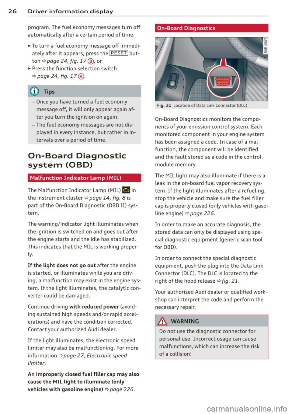
Fig. 21 Location of Data Li nk Conn ecto r (DLC)
On-Board D iagnostics monitors the compo
nents of your emission control system . Each
monitored component in your engine system
has been ass igned a code . In case of a mal
function, the component will be identified
and the fault stored as a code in the control
module memory.
The MIL light may also illuminate if there is a
leak in the on-board fuel vapor recovery sys
tem .
If the light illuminates after a refueling,
stop the vehicle and make sure the fuel filler
cap is properly closed (only vehicles with gaso
line engine) ¢
page 226.
In order to make an accurate diagnosis, the
stored data can only be displayed using spe
cial diagnostic equipment (generic scan tool
for OBD).
In order to connect the special diagnostic
equipment, push the plug into the Data Link
Connector (DLC). The DLC is located to the
right of the hood release
¢fig. 21.
Your authorized Audi deale r or qualified work
shop can interpret the code and perform the
necessary repair.
.&_ WARNING ~ -
Do not use the diagnostic connector for
personal use. Incorrect usage can cause
malfunctions, which can increase the risk
of a collision!
Page 93 of 316
Press brake pedal to release parking brake
This driver message appears when the switch
to release the parking brake was pressed. The
parking brake can only be released if yo u step
on the brake pedal and at the same time press
the switch or you automatically re lease the
parking brake with the starting assist
<=>page 89.
fpii Parking brake malfunction!
This driver message appears together with
the yellow
rm symbol when there is a parking
brake malfunction.
Start-Stop-System
Descript ion
A ppl ies to vehicles: with Sta rt-Stop-System
The Start-Stop -System can help increase fuel
economy and reduce CO
2 emissions.
In the Start-Stop-mode, the eng ine shuts off
automatically when the vehicle is stopped,
such as at a traffic light. The ignition remains
sw itched on during this stop phase. The en
gine will be automatically restarted when
needed.
The last Start-Stop-System setting (o n/off us
ing the button
lr.;, .. I) will be restored when the
ignition is turned on. The LED in the
1r.;, .. 1 but
ton turns on when the Start-Stop-System is
switched off manually.
Basic requirements for the Start-Stop
mode
- The driver's door is closed .
- The driver's seat belt is latched.
- The hood is closed.
- The vehicle must have been driven faster
than 2.5 mph (4 km/h) since the last stop .
- A tra iler is not hitched to the veh icle .
A WARNING
- Never turn off the engine before the ve
hicle has come to a complete stop. The
full function of the brake booster and the
power steering is not guaranteed. You
On the road 91
must use more force to turn or brake if
necessary. Because you cannot steer and
brake as you usually would, this could
lead to crashes and ser ious injuries.
- To reduce the risk of injuries, make sure
that the Start-Stop-System is turned off
when working in the engine compart
ment
c:> page 93.
(D Note
Always switch off the Start-Stop-System
when driving through water
c:> page 93.
Starting /stopping the engine
App lies to vehicles: wit h Start -Stop -System
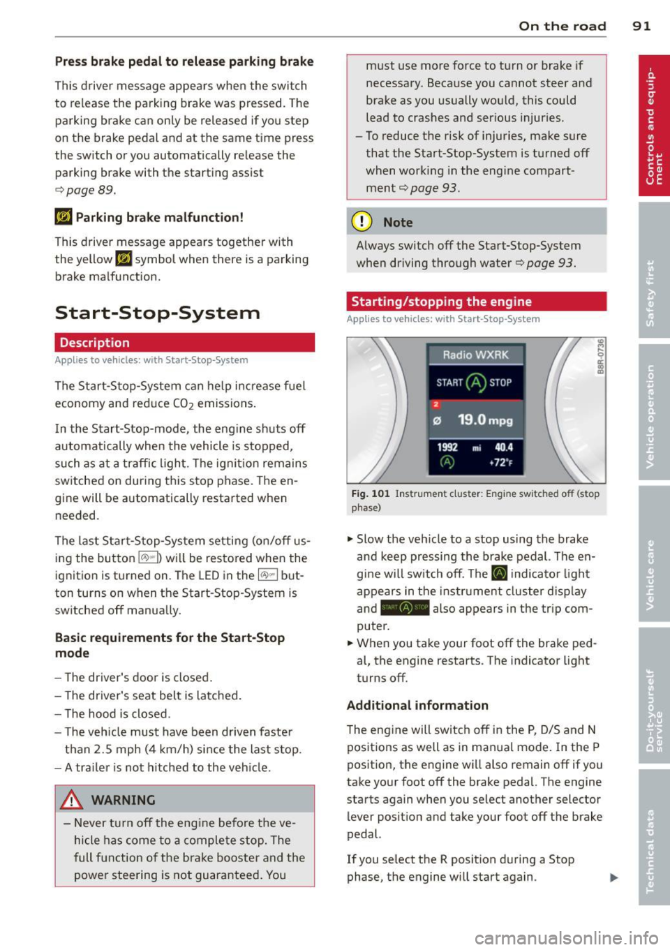
Fig. 101 Instrum ent cluster: Engine switched off (stop
phase)
.,. Slow the veh icle to a stop using the brake
and keep pressing the brake pedal. The en
gine will switch off. The
ti] indicator light
appears in the instrument cluster disp lay
and - also appears in the trip com
puter .
.,. When you take your foot off the brake ped
al, the engine restarts . The indicator light
turns off.
Additional information
T he engine will switch off in the P, D/S and N
positions as well as in ma nual mode. In the P
position, the engine will also remain off if you
take your foot off the brake pedal. The engine
starts again when you select another selector lever position and take your foot off the brake
pedal.
If you se lect the R position during a Stop
phase, the engine will start again .
Page 233 of 316
Checking and filling Engine hood
Releasing the engine hood
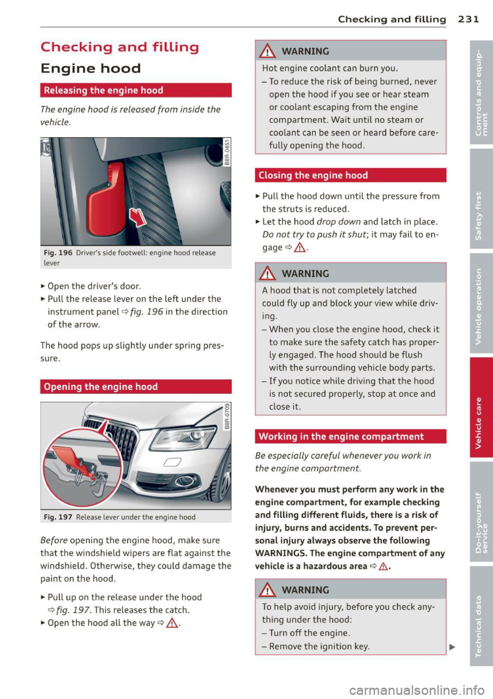
The engine hood is released from inside the
vehicle .
Fig. 196 Dr iver's side footwell: engin e hood release
lever
"' Open the driver's door .
"' Pull the release lever on the left under the
instrument panel
i=> fig. 196 in the d irection
of the arrow .
The hood pops up slightly under spring pres
sure.
Opening the engine hood
F ig . 197 Release lever under the engine hood
Before opening the engine hood, make sure
that the windshield wipers are flat against the
windshie ld. Otherwise, they could damage the
paint on the hood.
"' Pull up on the release under the hood
r::!> fig . 197 . This releases the catch.
"' Open the hood all the way
i=> .&,.
Checkin g and fillin g 231
A WARNING
Hot engine coolant can burn you.
- To reduce the risk of being burned, never
open the hood if you see or hear steam
or coolant escaping from the eng ine
compartment . Wait unt il no steam or
coolant can be seen or heard before care
fu lly opening the hood.
Closing the engine hood
"' Pull the hood down until the pressure from
the struts is reduced.
"' Let the hood
drop down and latch in p lace.
Do not try to push it shut; it may fail to en
gage
c;, .&, .
A WARNING
--
A hood that is not completely latched
could fly up and block your view while dr iv
ing.
- When you close the engine hood, check it
to make sure the safety catch has proper
ly engaged. The hood should be flush
with the surround ing vehicle body parts.
- If you notice while driv ing that the hood
is not secured properly, stop at once and
close it .
Working in the engine compartment
Be especially careful whenever you work in
the engine compartment.
Whenever yo u must pe rform any w ork in the
e n g ine com pa rt ment, for e xample ch ecki ng
and filling different fluids, th ere is a risk of
injury , burn s and accid ent s. T o pr eve nt per
so nal injury alwa ys obs erve the foll owing
WARNINGS . The en gine c ompa rtment of an y
vehicl e is a hazardou s are a
c;, Lh,.
A WARNING ~
To help avoid injury, be fo re you check any
thing under the hood:
- Turn off the engine.
- Remove the ignition key.
Page 291 of 316
Technical Data
Vehicle identification
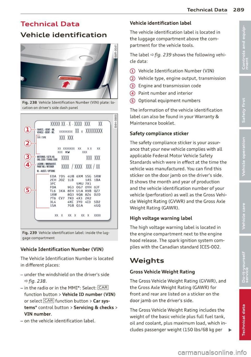
F ig. 238 Veh ide Identificat ion Numbe r (VlN) plate: lo ·
c ation on dri ver 's s ide das h pane l
XXXXX XX · X -XXXX XXX
~ fAllftlli. -llllll · NR. ~ W!ru -IIOO -NO.
xx
XXXX XXXX XX X XXXXXXXX
XXX XXX
IYP /TYPE
XX XXXXXXX XX X X XX
XXX KW XXX
®i ~W.::·f :l~~ XXXX XXX XXX
©+ ::rw= xxxx I xxxx XXX I xx
M. · AUSSt I IJ'IIDIIS
~--
EOA 7D 5 4UB 6XM SSG SRW
2E H JDZ 1LB lA S 1BA
3FC SMU 7X l
FD A 9G3 OG7 OYH OJF
TL6 3 KA 8EH UlA X98 027
lXW 803 908 824 D2D
7T6 CV7 7KO 4X3 2K2
3L4 4KC 3YO 413 502
1S A 7GB 01A 4GO
XX. X XX X XX X XXXX
Fig. 239 Vehicle identificat io n label: ins ide t he lug
ga ge compar tmen t
Vehicle Id entification Numb er (VlN )
The Veh icle Iden tifica tion Number is located
in different p laces :
- under the w indshield on the driver's side
¢fig. 238.
- i n the radio or in the MM!*: Select:
ICAR I
function button > Vehicle ID numb er (VIN )
or select I CAR I func tion button > Car sys·
tem s* control button > Servicin g & check s >
VIN numbe r.
-on the vehicle identification label.
Te chni cal Data 289
Vehicle id ent ification label
T he vehicle identification label is located in
the luggage compartment above the com
partment fo r th e ve hicle tools.
T he label¢
fig. 239 shows the fol low ing vehi
cle data :
(D Vehicle Ident ificat ion Number (VIN)
@ Vehicle type, engine o utp ut, transmission
® Engine and transmission code
© Paint number and inte rior
® Optional equipment numbers
T he information of the vehicle identification
label can also be found in your Warranty
&
Maintenance booklet .
Safety compliance sticker
T he safety compliance sticker is your assur
ance that your new veh icle complies with all
applicable Fede ra l Motor Vehi cle Safety
Standards which were in effect at the time the
vehicle was manufactured . You can find this
sticker on the door jamb on the driver 's side.
It shows the month and year of production
and the vehicle ident ificat ion number of your
vehicle (perforation) as well as the Gross Veh i
cle Weight Rating (GVWR) and the Gross Axle
Weight Rating (GAWR) .
High voltage warning label
The high voltage warning label is located in
the engine compartment next to the engine
hood release. The spark ign ition system com
plies with the Ca nadian standard ICES-002 .
Weights
Gross Vehicle Weight Rating
The Gross Vehicle Weight Rat ing (GVWR), and
the Gross Axle Weight Rati ng (GAWR) for
front and rear are listed on a sticker on the
doo r jamb on the driver's side.
The Gross Vehicle Weight Rat ing includes the
weight of the basic vehicle plus full fuel tank,
o il and coolant, plus maximum load, which in
cludes passe nger we ight (150 lbs/68 kg per
II>--
Page 304 of 316
302 Index
Electronic differential lock (EDL) ...... . 19 7
Warning/indicator lights ... .. ... . 15, 17
E lect ronic immobilize r ...... .. .. .... .. 38
Electronic power control (EPC) warn ing/ indicator light . .. .. .. .. 15
Elect ronic Stabilization Control (ESC) . .. 197
Hill descent assist ..... ... .. .. .... . 199
Offroad mode . ........... .... .... . 198
Warn ing/ indicator lights ... .. .. .. .. . . 15
E mergency braking . . . . . . . . . . . . . . . . . . . 90
Emergency flasher . . . . . . . . . . . . . . . . . . . 52
Warn ing/ indicato r lights ....... .. .. .. 16
Emergency key . .... ....... .. .. .... .. 36
Starting engine ............ .. .... .. 85
Emergency locking of the doors ..... ... . 4 2
Eme rgency operation
L uggage compartment lid .. .. .. .. .. . . 45
Emergency release Selector lever ............ .. .. .. .. . 128
Emergency starting ..... ... .. .. .... . 283
Emergency towing ............. .. ... 285
Emergency unlocking Ignition key . . . . . . . . . . . . . . . . . . . . . . . 38
E nergy management .. ... .. .. ... ... . 203
Eng ine
Compartment . .. ...... ... .. .. .. .. . 233
Coolant .. .... ........... .. .. .. .. . 238
D ata .. .. ... ............ .. .. .. .. . 291
H ood . ...... .. .. ..... ... .. .. .... . 23 1
Jump starting .. .. ..... ... .. .. .... . 105
Start-Stop-System . . . . . . . . . . . . . . . . . . 91
Starting . . . . . . . . . . . . . . . . . . . 83, 86, 98
Starting with jumper cables .. .. .... . 283
Stopping . . . . . . . . . . . . . . . . . . . 85, 87, 98
Engine compartment Safety instructions . . . . . . . . . . . . . . . . . 23 1
Working the engine compartment .... 231
E ng ine coolan t sys tem ...... .. .. .... . 238
Adding coolant . .. ..... ... .. .. .... . 239
Checking coolant leve l ... .. .. ... ... . 239
Malfunction . . . . . . . . . . . . . . . . . . . . . . . 30
Radiator fan ............. .. .. .. .. . 240
E ng ine coolan t temperature
Tempe ratu re ga uge .. ... .. .. .... .. .. 1 0
E ng ine hood
C losing .. .. ................ ... .. . 23 1
H ow to release the hood . .. .. .. .. .. . 23 1 E
ngine oi l .. .... .. ... .. ..... .... . .. 233
Adding ... .... .. .. ... ..... ... .. .. 236
Additives . ... .. .. .. ... ..... ... .. .. 236
Changi ng ..... .. ............. .... 237
Check oil level . .. ............. .... 236
Consumption .. .. ................ . 236
Level .... ... .. .. .. ... .. ... ..... .. . 34
Oil consumpt io n .. .......... ...... . 235
Oil g rades . .. .. . .............. .. .. 233
Press ure ma lfu nction ........... .. .. . 30
Senso r defec tive . . . . . . . . . . . . . . . . . . . . 34
S peci fication and viscosit y ........ . .. 233
E ngine speed limitation . . . . . . . . . . . . . . . 34
Environment Break-in per iod . .. ............. .... 205
Catalytic co nverter ................ . 206
Diesel pa rticula te filter .......... ... 206
Dispos ing of your veh icle battery . . . . . 245
Driv ing at high speeds .......... .. .. 20 7
D riv ing to minimize po llution and noise 20 7
F uel .. .. .. .. .. . .............. .. .. 226
Fuel economy .... .. ... ..... ... .. .. 207
Leaks under you r vehicle ..... ... .. .. 231
Letting the vehicle stand and warm up. 208
Proper disposal of drained brake fluid . 241
Proper disposal of drained eng ine cool-
ant .. ..... ... .. .. ... ........... . 239
Proper d isposal of drained eng ine
o il . . . . . . . . . . . . . . . . . . . . . . . . . 236,237
Recycling used eng ine oil ........ .. .. 236
Roof rack . .. .. .. ............. .. .. . 72
U nleaded fuel .... .. .... .... ... .. .. 222
What s hou ld I do with an o ld battery? . 245
E P C
refer to Elect ro nic powe r contro l ... .. . 15
ESC
refer to Electronic Stabilization Control
(ESC) ........ ... .. .............. .. 15
Ethy l alcohol (Fuel) ... ... ..... ... .. .. 223
E vent Data Recorde r (EDR ) ........ .... 19 7
Exhaust tail pipes Cleaning ...... .. .. ... ........... . 219
Expansion tank .... ... .. ..... ... .. .. 239
E xplanation of some technical te rms 210
Exterior mirrors Adjusting ..... .. .. ... ........... .. 57
Dimm ing .. ... ... .. .............. .. 58
Heating ..... .. .. .. ... .. ... ..... .. . 57
Page 309 of 316
Rear seats Adjusting seat ... ..... ... .. .. .. .... 64
Rearview camera Park ing mode 1 .......... .. .. .. ... 132
Park ing mode 2 .......... .. .. .. ... 132
Rear v iew mir ror . . . . . . . . . . . . . . . . . . . . . 58
Rear window heating .... ... .. .. .. .. .. 81
Recirculation mode (cl imate control) .. .. 80
Red symbols . . . . . . . . . . . . . . . . . . . . . . . . 28
Refill engine oil . . . . . . . . . . . . . . . . . . . . . . 31
Refue lling ................... ... ... 226
Gasoline inhib itor f lap ..... .. .. .. .. . 226
Release lever for hood ...... .. .. .. .. . 231
Remote cont rol
Homelink . ... ... ..... ... .. .. .. ... 135
Remote control key Un loc king and locking ..... .. .. .. .. .. 40
Remote rear lid release ..... .. .. .. .. .. 43
Repa ir manua ls ... ...... ... .. .. .. ... 293
Repai rs
A irbag system ........... .... .. ... 170
Replacing A fuse . .. .. ................. .. .. . 279
Light bulbs . ................ ... ... 282
T ires and whee ls ...... .... ... ... .. 259
Replacing w iper blades ..... .. .. .. .. .. 55
Report ing Safety Defects . . . . . . . . 146, 147
Reset button ........... .... ... ... ... 13
Retractor .... ... .. ..... ... .. .. .. ... 152
Right hand d rive .. .. .... .... . .... .. .. 5 1
Rims Clean ing . .. ............. .... .. ... 219
Roof rac k . . . . . . . . . . . . . . . . . . . . . . . . . . . 70
Attac hment points ..... ... .. .. .. .. .. 71
Install ing the attachments . .. .. .. .. .. 72
Instal ling the roof rack .... .. .. .. .. .. 71
Roof load .. ............. .... .. .... 72
Rule of behavio r offroad .. ... .. .. .. .. . 2 10
s
Safe driving hab its ......... .. .. .. .. . 139
Safety belt position .. ...... .. .. .. .. . 153
Safety belt he ight adjustment .. ... .. 155
Safety belts worn by p regnant women . 154
Safety belt pretens ioner ..... .. .. .. .. . 155
Service and disposal ...... .. .. .. .. . 156
Inde x 307
Safety be lts ... .... .. . .. .. ..... ... .. 152
Cleaning . ... .. .... . ... ...... ... .. 219
Danger to passengers who do not wear a
safety belt .. .. .. ................. 150
Fastening . .. .. .. .... ............. 152
Height adj ustment .. .............. . 155
Improperly worn ... . .. .. .. ... ... .. 155
Not worn ....... .. ..... .......... 150
Safety be lt pos ition . ........... .... 153
S afety i nstr uctions .... ......... .. .. 152
Securing child safe ty seats ... ... .. .. 188
Spec ia l considerations for pregnant
women ... .. .. .... . ... ...... ... .. 154
U nfastening . .. .. ................. 154
Warning/ind icator light ......... 17,149
Why YOU MUST wear them ........ .. 149
Wor n properly .... ............... . 151
Safety comp liance sticker ..... ... .. .. 289
Safety eq uipme nt .. .... ......... .. .. 139
Safety features for occupant restraint and protection .. .. .. .. .... ... .... .... .. 139
Safety guidelines Seat adjustment . . . . . . . . . . . . . . . . . . . . 61
Safety instr uctions
E ngine comp art ment .. ......... .. .. 231
f or side c urtain airbags . ..... ... .. .. 177
for using child safety seats ... ... .. .. 181
for using safety belts . ... .... ... .. .. 152
Monitoring the Advanced Airbag Sys-
tem ........ .. .. ................. 170
Safety systems Warning/ind icator lights ..... ... .. .. . 16
Seat Heating ... .. .. .. ... ............ .. . 81
N umber of sea ts ..... ........... .. 149
Ventila tion . ... .... .. .. ...... ... .. . 81
Seat adjustment . . . . . . . . . . . . . . . . . . . . . 62
Drive r's seat . . . . . . . . . . . . . . . . . . . . . . . 61
Fron t passenger's seat . . . . . . . . . . . . . . . 62
F ron t se ats . . . . . . . . . . . . . . . . . . . . . . . . 61
Hea d restra ints .... . .. ..... ... .. .. 142
Memory . ... .. .... . ... ...... ... .. . 63
Seat be lts
refer to Safety belts . . . . . . . . . . . . . . . . 149
Seat covers Cleaning .. .. .. .... .. ........ ..... 220
Seating capacity ... .. . ... .... ... .. .. 149
•
•