AUDI Q5 2016 Owners Manual
Manufacturer: AUDI, Model Year: 2016, Model line: Q5, Model: AUDI Q5 2016Pages: 300, PDF Size: 75.02 MB
Page 271 of 300
,....,
N
co
er::
co
,....,
whenever you need to change a bulb.
Fuses and bulbs
269
Page 272 of 300
Emergency situations
Emergency situations
General
This chapter is intended for trained emergency crews and working personnel who have the nec
essary tools and equipment to perform these
operations.
Starting by pushing or
towing
CD Note
Vehicles with an automatic transmission
cannot be started by pushing or towing.
Starting with jumper
cables
If necessary, the engin e con be started by con
necting it to the battery of another vehicle.
If the engine should fail to start because of a dis
charged or weak battery, the battery can be con
nected to the battery of
another vehicle, using a
pair of jumper cables to start the engine.
Jumper cables
Use only jumper cables of sufficiently large cross
section
to carry the starter current safely. Refer
to the manufacturer's specifications.
Use only jumper cables with
insulated terminal
clamps which are distinctly marked :
plus(+) cable in most cases colored red
minus(-) cable
in most cases colored black.
A WARNING
Batteries contain electricity, acid, and gas.
Any of these can cause very serious or fatal in
jury. Follow the instructions below for
safe
handling of your vehicle's battery.
-Always shield your eyes and avoid leaning
over the battery whenever possible.
-A discharged battery can freeze at tempera
tures just below 32 °F (0 °C). Before con
necting a jumper cable, you must thaw the
270
frozen battery completely, otherwise it could explode.
- Do not allow battery acid to contact eyes or
skin. Flush any contacted area with water immediately.
- Improper use of a booster battery to start a
vehicle may cause an explosion.
- Vehicle batteries generate explosive gases.
Keep sparks, flame and lighted cigarettes
away from batteries.
- Do not try to jump start any vehicle with a
low acid level in the battery.
- The voltage of the booster battery must also
have a 12-Volt rating. The capacity (Ah) of
the booster battery should not be lower
than that of the discharged battery. Use of
batteries of different voltage or substantial
ly different "Ah" rating may cause an explo
sion and personal injury.
- Never charge a frozen battery. Gas trapped in the ice may cause an explosion.
- Never charge or use a battery that has been
frozen . The battery
case may have be weak
ened .
- Use of batteries of different voltage or sub
stantially different capacity (Ah) rating may
cause an explosion and injury. The capacity
(Ah) of the booster battery should not be
lower than that of the discharged battery.
- Before you check anything in the engine
compartment, always read and heed all
WARNINGS
~page 220.
CD Note
-Applying a higher voltage booster battery
will cause expensive damage to sensitive
electronic components, such as control
units, relays, radio, etc.
- There must be no electrical contact between
the vehicles as otherwise current could al
ready start to flow as soon as the positive
(+) terminals are connected.
@ Tips
- The discharged battery must be properly
connected to the vehicle's electrical system. .,..
Page 273 of 300
..... N
co ~ CX)
..... I.Cl U"I
..... I.Cl .....
When jump starting or charging the bat
tery, never connect the negative ground ca
ble to tbe battery negat ive post because the
battery manager system must be ab le to de
tect the battery's state of charge. Always
connect the negative ground cable to the
negative ground post of the battery manag
er contro l unit .
Use of jumper cables
Make sure to connect the jumper coble clomps in
exactly the order described below!
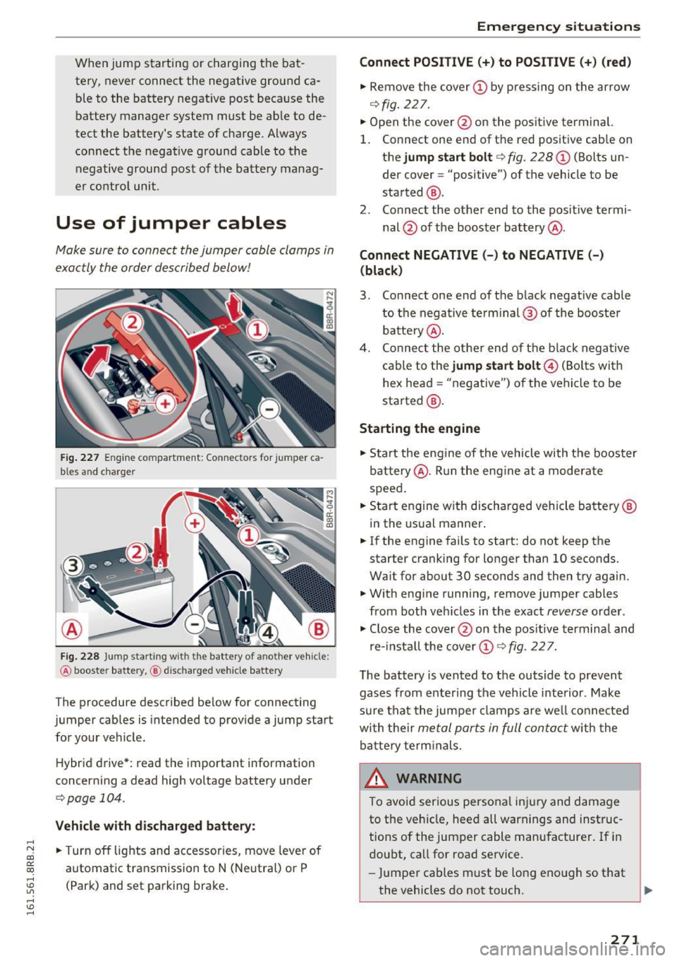
Fig. 227 Engine co mpartment: Connectors for jumper ca
b les and charger
Fig. 228 Jump starting w ith the bat tery of a nother vehicle:
@ booste r battery, @ discha rged veh icle battery
The procedure described below for connecting
jumper cables is intended to provide a jump start for your vehicle.
Hybrid drive*: read the important information
concerning a dead high voltage battery under
c;;,poge 104.
Vehicle with discharged battery:
.. Turn off lights and accessories, move lever of
automatic transmission to N (Neutral) or P
(Park) and set parking brake .
Emergency situations
Connect POSITIVE(+) to POSITIVE (+) (red)
.. Remove the cover@ by pressing on the arrow
¢fig. 227.
.. Open the cover @on the positive terminal.
1. Connect one end of the red positive cab le on
the
jump start bolt r=;;, fig. 228 @ (Bolts un
der cover= "positive") of the vehicle to be
started @.
2. Connect the other end to the positive termi-
nal @ of the booster battery @.
Connect NEGATIVE(-) to NEGATIVE(-)
(black)
3. Connect one end of the black negative cable
to the negative te rm i nal @of the booster
battery @.
4. Connect the other end of the bla ck negative
cable to the
jump start bolt@ (Bolts wi th
hex head = "negative") of the vehicle to be
started @.
Starting the engine
.. Start the engine of the vehicle with the booster
battery @. Run the eng ine at a moderate
speed .
.. Start engine w ith discharged vehicle battery®
in the usual manner .
.. If the engine fails to start: do not keep the
starter cranking for longer than 10 seconds.
Wait for about 30 seconds and then try again .
.. With eng ine running,
remove jumper cables
from both veh icles in the exact
reverse order .
.. Close the
cover @on the positive terminal and
re-install the cover (!)¢
fig. 227.
T he battery is vented to the outside to prevent
gases from entering the vehicle interior . Make
sure that the jumper clamps are well connected
with their
metal ports in full contact with the
battery term inals.
& WARNING ~
To avoid serious personal injury and damage
to the veh icle, heed all warnings and instruc
tions of the jumper cable manufacturer. If in
doubt, call for road
service.
-Jumper cables must be long enough so that
the vehicles do not touch.
~
271
Page 274 of 300
Emergency situations
-When connecting jumper cables, make sure
that they cannot get caught in any moving
parts in the engine compartment.
- Do not bend over the batteries -danger of
chemical burns!
- The battery cell locking screws must be
tightened securely.
- Before you check anything in the engine
compartment, always read and heed all
WARNINGS
c> page 220.
(D Note
Improper hook-up of jumper cables can ruin
the generator .
- Always connect POSITIVE(+) to POSITIVE
(+), and NEGATIVE(-) to NEGATIVE(-)
ground post of the battery manager control
unit.
- Check that all screw p lugs on the battery
cells are screwed in firmly. If not, tighten
plugs prior to connect ing clamp on negative
battery terminal.
- Please note that the procedure for connect
i ng a jumper cable as described above ap
plies specifically to the case of your vehicle
being jump started . When you are giving a
ju mp start to another vehicle , do
not con
nect the negative (-) cable to the negative
(-) terminal on the discharged batte ry @
c> fig. 228. Instead, securely connect the
negative( -) cab le to either a solid metal
component that is firm ly bolted to the en
gine block or to the engine block itself. If
the battery that is being charged does not
vent to the outside, escap ing battery gas
could ignite and explode !
Towing with a tow truck
General hints
Your Audi requires special handling for towing.
The following information is to be used by com
mercial tow truck operators who know how to op
erate the ir equipment safely.
-Never tow your Audi, towing will cause dam
age to the engine and transmission.
272
-Never wrap the safety chains or winch cables
around the brake lines .
- To prevent unnecessary damage, your Audi
must be transported with a flat bed truck .
- To load the vehicle on to the flat bed, use the
towing loop found in the vehicle tools and at
tach to the front or rear anchorage
i:>pag e 272 and i:> page 273.
A WARNING
A vehicle being towed is not safe for passen
gers . Never allow anyone to ride in a vehicle
being towed, for any reason.
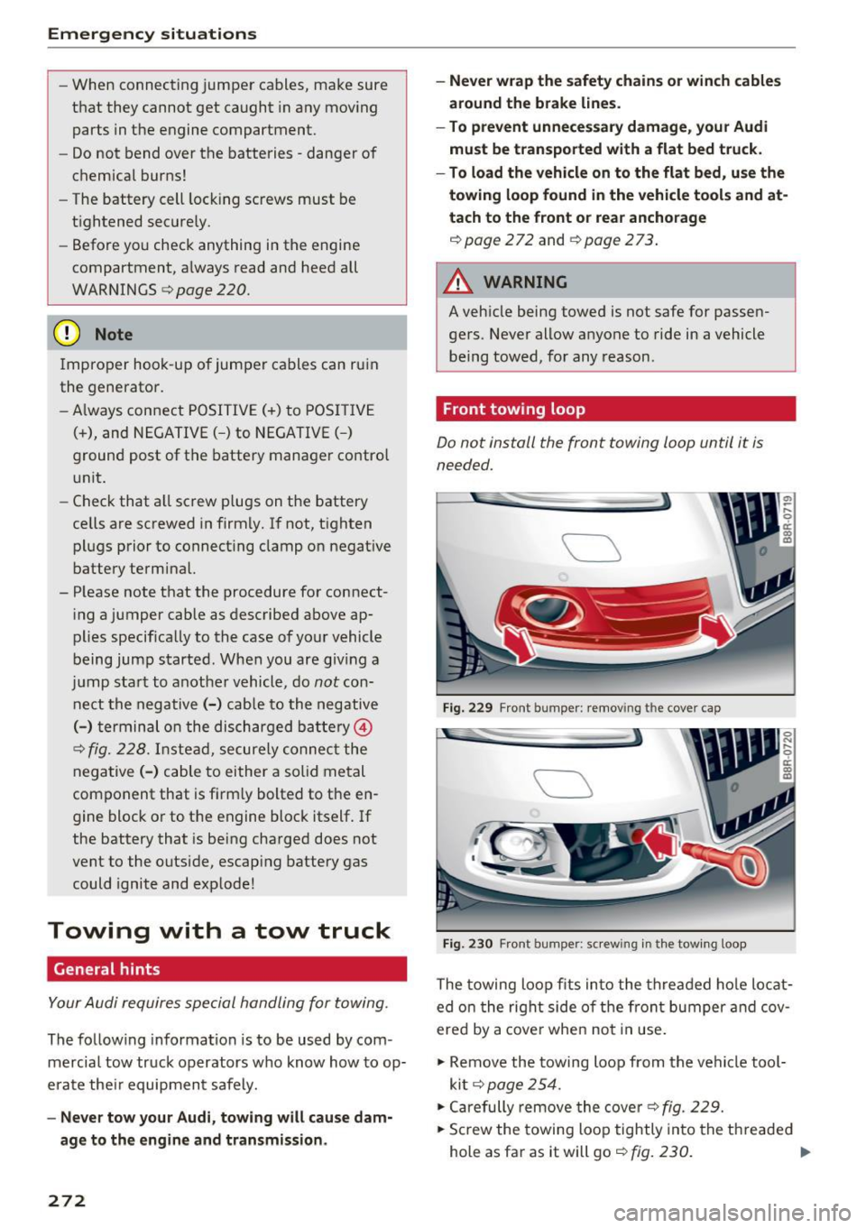
Front towing loop
Do not install the front towing loop until it is
needed.
Fig. 229 Front bumper : remov ing the cover cap
Fig. 230 Front bumper: s crew ing in t he towing loop
The towing loop fits into the threaded hole locat
ed on the right side o f the front bumper and cov
ered by a cover when not in use.
.,. Remove the towing loop from the vehicle tool
kit
c> page 254 .
.,. Carefully remove the cove r c> fig. 229.
.,. Screw the towing loop tightly into the threaded
hole as far as it will go
c> fig. 230. Ill>
Page 275 of 300
..... N
co ~ CX)
..... I.Cl U"I
..... I.Cl .....
When it is no longer needed, unscrew the towing
loop and put it back into the vehicle toolkit. Be
sure to have the towing loop stored in the vehicle
at all times.
When r e-installing the cover be sure to first in
sert the tabs on the cover into the retainers near
the radiator grille. Then install the other side of
the cover and push it into the retainers
¢fig. 229.
The appearance of the cover varies from the i llus
tration for some model vers ions.
.&_ WARNING
If the towing loop is not screwed in as far as it
will go, the thread can pull out when the vehi
cle is towed -potential risk of an accident.
(D Note
The cover is attached to the bumper with sev
eral hooks. Do not use excessive force when
removing the cover to avoid damag ing it.
Rear towing loop
On vehicles without a factory-installed trailer
hitch*, the threaded hole for the towing loop is
on the right side of the rear bumper.
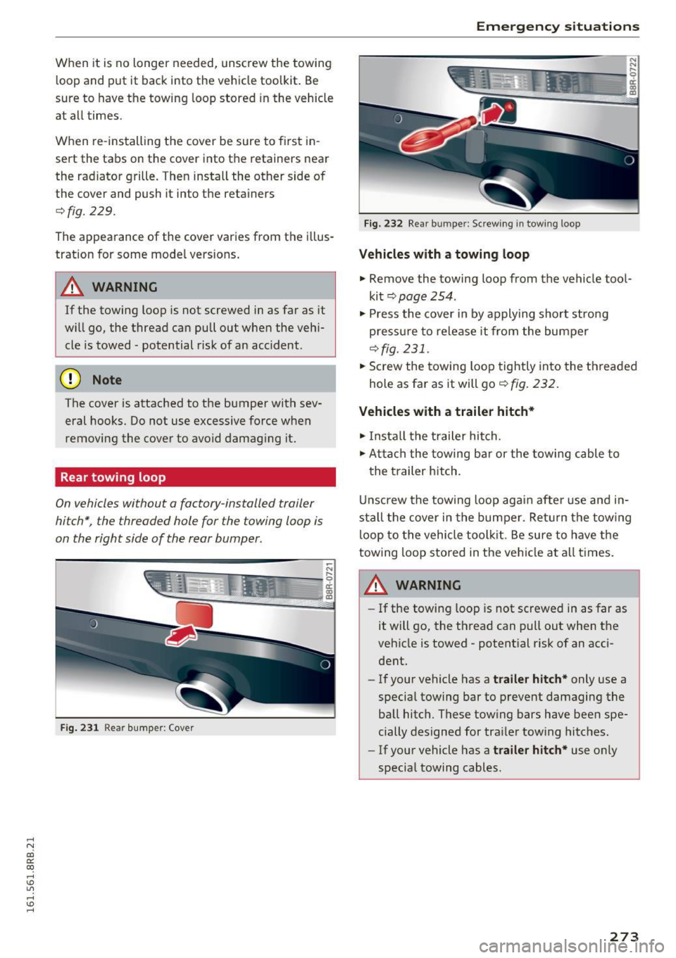
Fig. 231 Rear bumper: Cover
Emergency situations
Fig. 232 Rear bumper: Screw ing in towing loop
Vehicles with a towing loop
.,. Remove the towing loop from the vehicle tool
kit
c;, page 254.
.,. Press the cover in by applying short stro ng
press ure to release it from the bumper
¢fig. 231 .
.,. Screw the towing loop tightly into the threaded
hole as far as it will go
c;, fig. 232.
Vehicles with a trailer hitch*
.,. Insta ll the trailer hitch.
.,. Atta ch the towing bar or the towing cable to
the trailer hitch.
Unscrew the towing loop again after use and in
stall the cover in the bumper . Ret urn the towing
loop to the vehicle toolkit. Be sure to have the
towing loop stored in the vehicle at all times.
A WARNING
-If the towing loop is not screwed in as far as
it will go, the thread can pull out when the
vehicle is towed - potential risk of an acci
dent.
- If your vehicle has a
trailer hitch* only use a
special towing bar to prevent damaging the
ball hitch. These tow ing bars have been spe
cially designed for trailer tow ing hitches.
- If your vehicle has a
trailer hitch* use only
special towing cables .
273
Page 276 of 300
Emergency situations
Loading the vehicle onto a flat bed truck
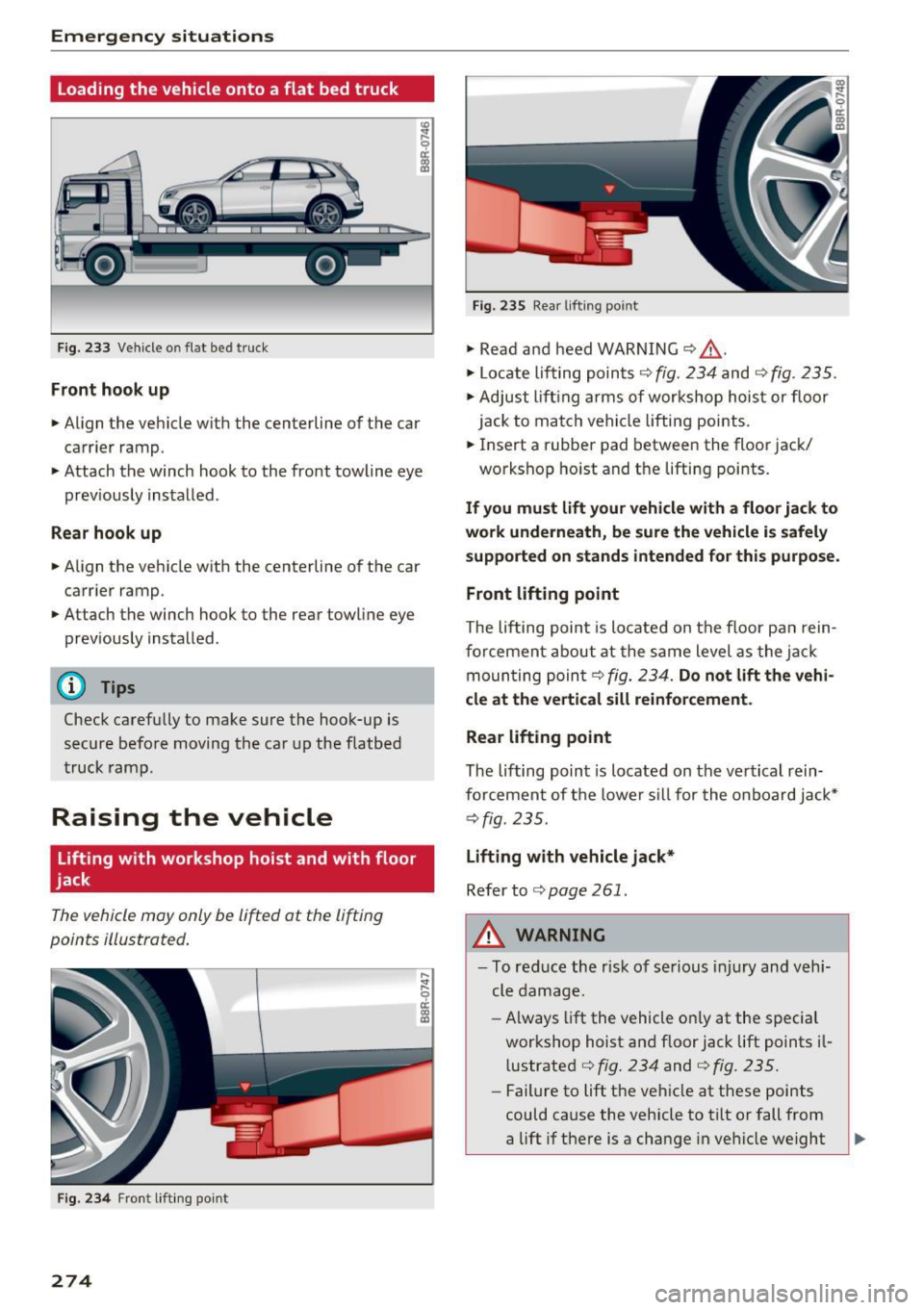
Fig. 233 Veh icle o n flat bed truck
Front hook up
.. Align the vehicle with the centerline of the car
carr ier ramp.
.. Attach the winch hook to the front towline eye
prev iously installed.
Rear hook up
.. Align the vehicle with the centerline of the car
carrier ramp.
.. Attach the winch hook to the rear towline eye
previously installed .
@ Tips
Check carefully to make sure the hook-up is
secure before moving the car up the flatbed
truck ramp.
Raising the vehicle
Lifting with workshop hoist and with floor
jack
The vehicle may only be lifted at the lifting
points illustrated.
Fig. 234 Front lifting point
274
Fig. 235 Rear lifting point
.. Read and heed WARNING ¢ f1..
.. Locate lifting points r;!) fig. 234 and c;!) fig. 235.
.. Adjust lifting arms of workshop hoist or floor
jack to match vehicle lifting points .
.. Insert a rubber pad between the floor jack/
workshop hoist and the lifting points .
If you must lift your vehicle with a floor jack to
work underneath, be sure the vehicle is safely
supported on stands intended for this purpose .
Front lifting point
The lifting point is located on the floor pan rein
forcement about at the same level as the jack
moun ting poin t¢
fig. 234. Do not lift the vehi
cle at the vertical sill reinforcement.
Rear lifting point
The lifting point is located on the vertical rein
forcement of the lower sill for the on board jack*
¢fig. 235.
Lifting with vehicle jack*
Refer to<=> page 261.
,&. WARNING
-To reduce the r isk of serious injury and vehi
cle damage.
- Always lift the vehicle on ly at the special
workshop hoist and floor jack lift points il
l ustrated <=>
fig. 234 and ¢ fig. 235.
-Failure to lift the vehicle at these points
could cause the vehicle to tilt or fall from
a lift if there is a change in vehicle weight
Page 277 of 300
,....,
N
co
er::
co
,....,
pen, for exam ple, when heavy compo
nents such as the engine b lock or trans
miss io n are removed.
- When removing heavy components like
th ese, anc hor vehicle t o hoist o r add corr e
sponding weights to maintain the center of
grav ity. Oth erwise, the ve hicle might ti lt or
s li p off the hois t, causing s erious person al
lnJUry.
(D Note
- Be awar e of the fo llowing poi nts before lift
i ng t he vehicle:
- The vehicle should never be lifted or
jacked up from underneath the engine oil pan , the transmission housing, the front
or rear axle or the body side members .
This could lead to serious damage.
- To avoid damage to the unde rbody or
chassis frame, a rubber pad must be in
serted between the floor jack and the lift
points.
- Before driv ing over a workshop hoist,
check that the vehicle weight does not
exceed the permissible lifting capacity of
the hoist .
- Before driving over a workshop hoist, en
sure that there is sufficient clearance be
tween the hoist and low parts of the ve
hicle.
Emergency situations
275
Page 278 of 300
Technical data
Technical data
Vehicle identification
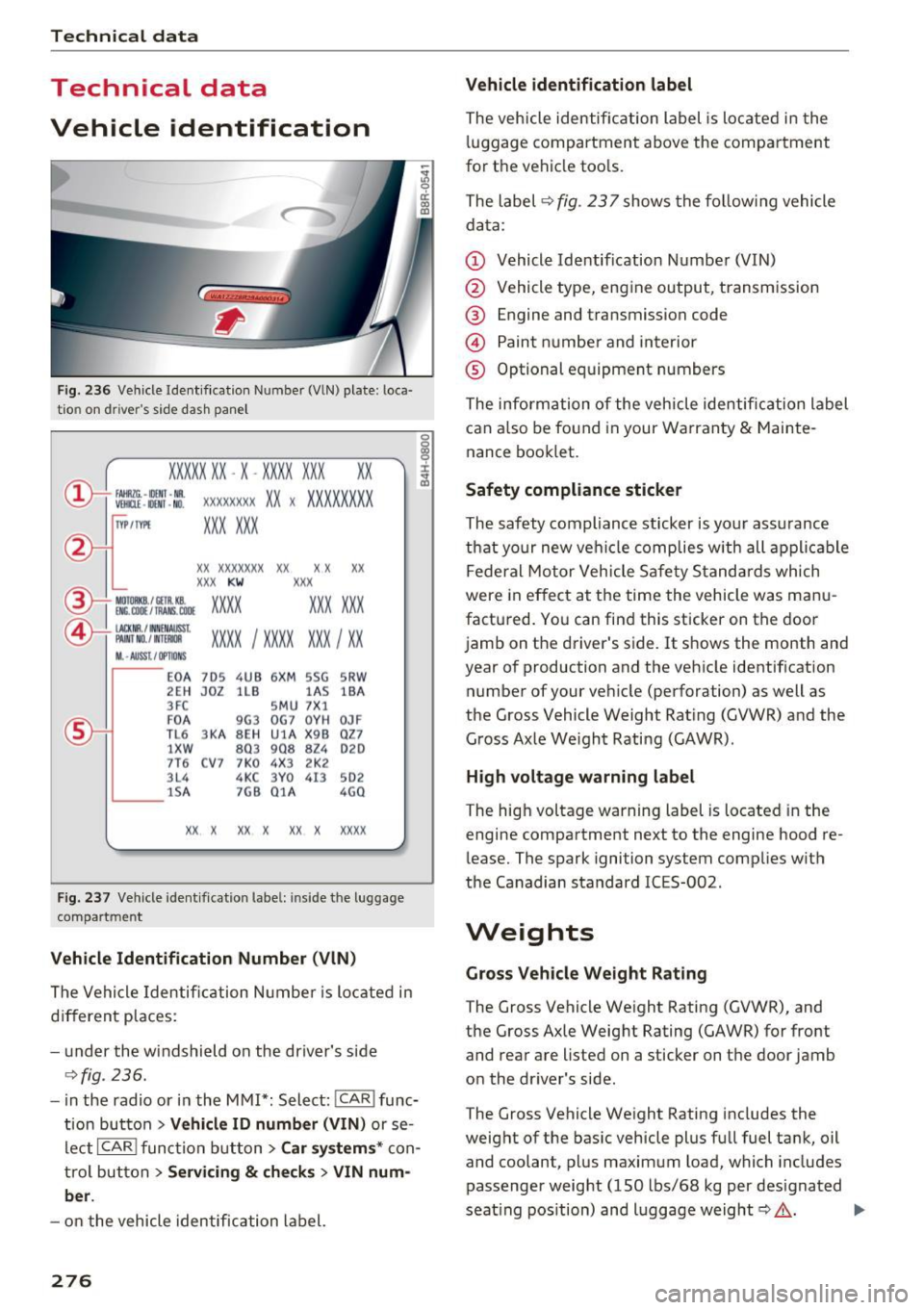
Fig. 236 Vehicle Ident if ication Numbe r (VlN) plate : loca·
tio n on d river 's side dash panel
XXXXX XX -X -XX XX XXX XX
@-+ ~J:~t::1 ::: xxxxxxxx xx x xxxx xxx x
IYP lf'VPE XXX X XX
xx xxxxxxx xx xx xx
XXX KW
XXX
EM:. COil / fAANS , COOE xxxx XXX XXX ®i MOIOlll
©-+ IAC KIIR . / tN NEN AIJSSt
XXXX I XXXX XXX I XX PAI NT NO./ WT£Jldl
II. -AUSST . / OPTIO NS
E0 A 7D5 4UB 6X
M SSG SR W
2EH JOZ lLB lAS
lBA
3FC SM U 7 X1
F0 A
9G3 0
G7 0Y H
0JF
TL 6 3 KA 8EH UlA X 9B Q
Z7
1 XW
803 908
824 020
7T6 C V7 7 K0 4X3 2K2
3L4 4KC 3Y0 413
502
lS A 7GB 01A
4G0
XX X XX X
XX X xxxx
Fig. 237 Vehicle identificat ion labe l: in side the luggage
compart ment
Vehicle Identification Number (VlN)
The Vehicle Identification Number is located in
different places :
- under the windshield on the driver's side
¢fig . 236.
- in the radio or in the MMI*: Select: !CAR i func·
tion button
> Vehicle ID number (VIN) or se·
Leet
I CAR ! function button > Car systems* con·
trol button
> Servicing & checks > VIN num
ber .
-on the vehicle identification label.
276
Vehicle identification label
The vehicle identification label is located in the
luggage compartment above the compartment
for the vehicle tools.
The label ¢
fig. 237 shows the following vehicle
data:
(D Vehicle Identification Number (VIN)
@ Vehicle type, engine output, transmission
® Engine and transmission code
@ Paint number and interior
® Optional equipment numbers
The information of the vehicle identification label
can also be found in your Warranty
& Mainte·
nance booklet.
Safety compliance sticker
The safety compliance sticker is yo ur ass urance
that your new vehicle complies with all applicable
Federal Motor Vehicle Safety Standards which
were in effect at the time the vehicle was manu
factured. You can find this sticker on the door
jamb on the driver's side. It shows the month and
year of production and the vehicle identification
number of your vehicle (perforation) as well as
the Gross Vehicle Weight Rating (GVWR) and the
Gross Axle We ight Rating (GAWR).
High voltage warning label
The high voltage warning label is located in the
engine compartment next to the engine hood re·
lease. The spark ignition system complies w ith
the Canadian standard ICES-002 .
Weights
Gross Vehicle Weight Rating
The Gross Vehicle Weight Rating (GVWR), and
the Gross Axle Weight Rating (GAWR) for front
and rear are listed on a sticker on the door jamb
on the dr iver's side .
The Gross Vehicle Weight Rating includes the
weight of the basic vehicle plus full fuel tank, oil
and coolant, plus maximum load, which includes
passenger weight (150 lbs/68 kg per designated
seat ing position) and luggage weight¢,&. .
Page 279 of 300
,....,
N
co
er::
co
,....,
The G ross Axle We igh t Rating is the max imum
l oad that can be applied at each axle of the vehi
cle ~.& .
Vehicle capacity weight
The vehicle capac ity we ight (max. load) is listed
on the drive r's side 8-p illar.
_& WARNING
- T he ac tual Gross Ax le Weight Ra ting a t the
front and rear axles sho uld not exceed the
permissible weights, and their combination
must not exceed the Gross Ve hicle We ight
Rating.
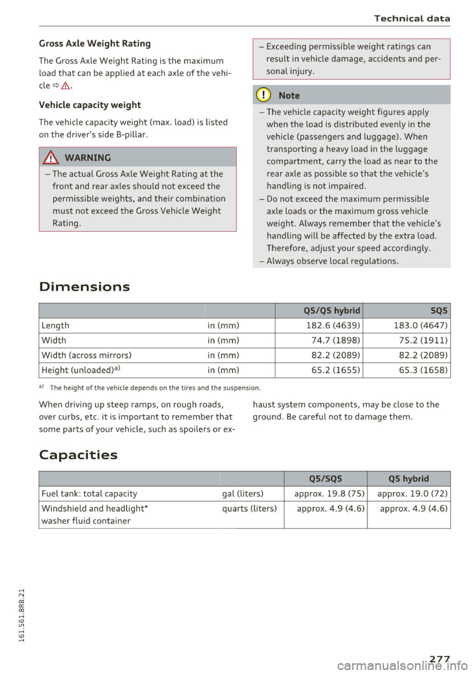
Dimensions
Leng th i
n (mm)
Width in (mm)
Width (a cross mirro rs) in (mm)
He ight (un loaded)al in (mm)
Technical data
- Exceeding permissible weight ratings can
res ult in vehicle damage, accidents and per
sonal injury.
(D Note
- The vehi cle capacity weig ht figures apply
when the load is d istributed evenly in the
vehicle (passengers and luggage) . When
transport ing a heavy load in the luggage
compartment, carry the load as near to the
rear axle as possib le so that the veh icle's
hand ling is not impaired .
- Do not exceed the maximum perm iss ible
ax le loads or the maximum gross vehicle
we igh t. Always remember that the veh icle's
han dling will be affe cted by the extra load.
Th erefore, adjust your spee d accordingly.
- Always observe local regulations.
QS /QS hybrid SQS
18 2.6 (4639) 183 .0 (464 7)
74.7 (1898) 75.2 (1911)
8 2.2 ( 2089) 82 .2 (2089)
65.2 (1655) 65 .3 (1658)
a ) T he heig h t of t he ve hicl e de pe nds on th e tir es and the suspen sio n.
When driving up steep ramps, on rough roads,
over curbs, etc . it is important to remember that
some pa rts of your vehicle, such as spo ile rs or ex- haust system components, may be close to the
ground. Be carefu
l not to damage them.
Capacities
QS /SQS QS hybrid
Fuel tank: tota l capacity gal (liters) approx. 19.8 (75) approx . 19 .0 (72)
Windsh ield and h eadlight* quarts (liters) approx . 4 .9 (4 .6) approx . 4 .9 (4 .6)
washer fluid container
277
Page 280 of 300
Tech nical data
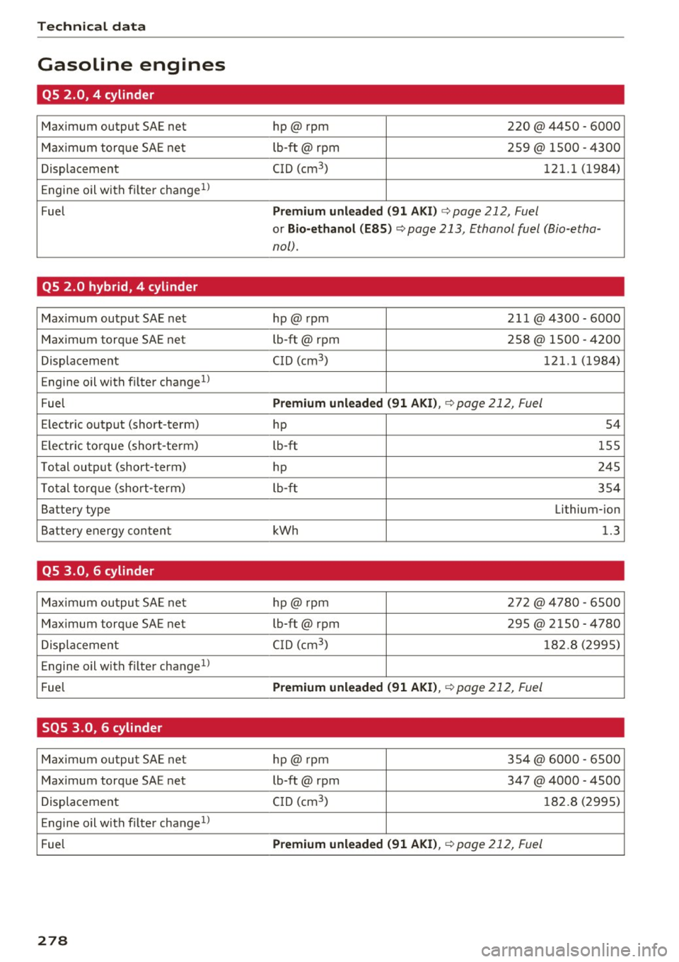
Gasoline engines
QS 2.0, 4 cylinder
Maximum output SAE net hp@ rpm 220 @ 4450 -6000
Max imum torq ue SAE net lb-ft@ rpm 259@ 1500 - 4300
Displacement CID (cm
3
) 121.1 (1984)
Engine oil with filter change
1>
Fuel Premium unl ead ed (9 1 A KI) c;, page 212, Fuel
or Bio-ethanol (E85 ) ¢ page 213, Ethanol fuel (Bio-etha-
no[) .
QS 2.0 hybrid, 4 cylinder
Maximum output SAE net hp@ rpm 211 @4300 -6000
Maximum torque SAE net lb-ft@ rpm 258 @ 1500 - 4200
Displacement C
ID (cm
3
) 1 21.1 (1984)
Engine oil with filter change
1
)
Fuel Premium unleaded (91 AKI) , ¢ page 212, Fuel
Electr ic output (short-term)
hp 54
El ectr ic to rque (short-te rm) lb-ft
155
Total output (short-term) hp 245
T otal torq ue (short-term)
lb-ft 354
Battery type Lithium-ion
Battery energy conten t kWh 1.3
QS 3.0, 6 cylinder
Max imum ou tput SA E net hp@ rpm 2
72@ 4780 -6500
Maximum torque SAE net lb-ft@ rpm 295 @2150 -4780
Displacement C
ID (cm
3
) 1 82 .8 (2995)
Engine oil with filter change
1l
Fuel Premium unleaded
(91 AKI) ,
c;, page 212, Fuel
SQS 3.0, 6 cylinder
Maximum ou tpu t SA E ne t hp@ rpm 354@ 6000
-6500
Max imum torq ue SA E net lb-ft@ rpm 347 @4000 -4500
Displacement C
ID (cm
3
) 1 82.8 (2995)
E ngine o il w ith f ilter change
1l
Fuel Premium unleaded
(91 AKI) ,
c;, page 212, Fuel
278