interior lights AUDI Q5 2016 Owners Manual
[x] Cancel search | Manufacturer: AUDI, Model Year: 2016, Model line: Q5, Model: AUDI Q5 2016Pages: 300, PDF Size: 75.02 MB
Page 4 of 300
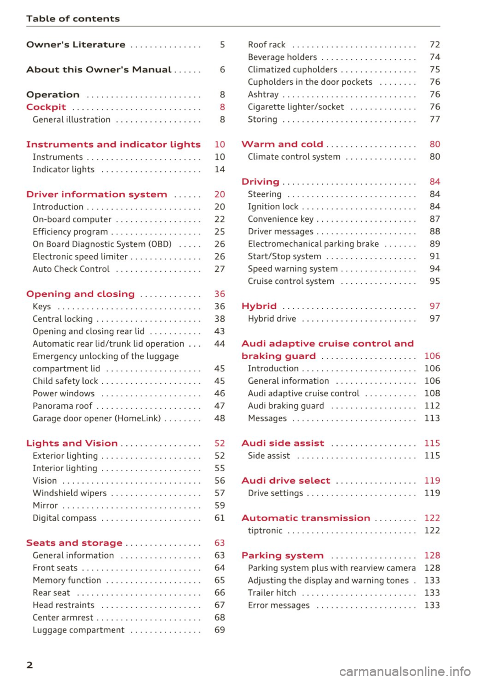
Table of contents
Owner's Literature
5
About this Owner's Manual . . . . . . 6
Operation . . . . . . . . . . . . . . . . . . . . . . . . 8
Cockpit . . . . . . . . . . . . . . . . . . . . . . . . . . . 8
General illustration . . . . . . . . . . . . . . . . . . 8
Instruments and indicator lights 10
Instruments . . . . . . . . . . . . . . . . . . . . . . . . 10
Indicator lights . . . . . . . . . . . . . . . . . . . . . 14
Driver information system . . . . . . 20
I n tr oduction . . . . . . . . . . . . . . . . . . . . . . . . 20
On -board computer . . . . . . . . . . . . . . . . . . 22
Efficiency program . . . . . . . . . . . . . . . . . . . 25
On Board Diagnostic System (OBD) . . . . . 26
Electronic speed limiter . . . . . . . . . . . . . . . 26
Auto Check Contro l . . . . . . . . . . . . . . . . . . 27
Open ing and closing . . . . . . . . . . . . . 36
Keys . . . . . . . . . . . . . . . . . . . . . . . . . . . . . . 36
Central locking . . . . . . . . . . . . . . . . . . . . . . 38
Opening and clos ing rear lid . . . . . . . . . . . 43
Automatic rear lid/trunk lid operation 44
Em ergency unlo cking of the luggage
compa rtment lid . . . . . . . . . . . . . . . . . . . . 45
Ch ild safety lock . . . . . . . . . . . . . . . . . . . . . 45
Power windows . . . . . . . . . . . . . . . . . . . . . 46
Panorama roof . . . . . . . . . . . . . . . . . . . . . . 47
Garage door opener (Home link) . . . . . . . . 48
Lights and Vision . . . . . . . . . . . . . . . . . 52
Exterior lighting . . . . . . . . . . . . . . . . . . . . . 52
Interior lighting . . . . . . . . . . . . . . . . . . . . . 55
V1s1on . . . . . . . . . . . . . . . . . . . . . . . . . . . . . 56
Windshield wipers . . . . . . . . . . . . . . . . . . . 57
Mirror . . . . . . . . . . . . . . . . . . . . . . . . . . . . . 59
Digital compass . . . . . . . . . . . . . . . . . . . . .
61
Seats and storage . . . . . . . . . . . . . . . . 63
Gene ral information . . . . . . . . . . . . . . . . . 63
Front seats . . . . . . . . . . . . . . . . . . . . . . . . . 64
Memory function . . . . . . . . . . . . . . . . . . . . 65
Rear seat . . . . . . . . . . . . . . . . . . . . . . . . . . 66
Head restraints . . . . . . . . . . . . . . . . . . . . . 67
Cente r armrest . . . . . . . . . . . . . . . . . . . . . .
68
Luggage compartment . . . . . . . . . . . . . . . 69
2
Roof rack ... .. .. .. .. ... .......... . .
Beverage holders ... .. .. ........... . .
Climatized cupholders ... . .......... . .
(upholders in the door pockets ...... . .
Ashtray ....... .. .. .. ............. . .
Cigarette lighter/socket ............. .
Stor ing ... .. .. .. .. .. ........ ..... . .
Warm and cold .. .. ... .. ..... ... . .
Climate control system ........ ..... . .
Dnv1ng ....... .. .. .. ............. . .
Steering ........ ... ............. .. .
Ig niti on lock ...... ... .............. .
Convenience key .. .. .. ... .. ... ... .. . .
Driver messages .. .. .. .. ........... . .
Electromechanical parking brak e ..... . .
Start/Stop system .... .. . .......... . .
Speed warning system .. .. .......... . .
Cruise control system
Hybrid ..... .. .. .. .. ... .......... . .
Hybrid dr ive ... .. .. .. .. ........... . . 72
74
75
76
76
76
77
80
80
84
84
84
87
88
89
91
94
95
97
97
Audi adaptive cruise control and
braking guard . . . . . . . . . . . . . . . . . . . .
106
Introd uction . . . . . . . . . . . . . . . . . . . . . . . . 106
Genera l information . . . . . . . . . . . . . . . . . 106
Audi adaptive cruise contro l . . . . . . . . . . . 108
Audi braking guard . . . . . . . . . . . . . . . . . . 112
Messages . . . . . . . . . . . . . . . . . . . . . . . . . . 113
Audi side assist . . . . . . . . . . . . . . . . . . llS
S ide assist .. .. .. .. .. ........ ..... .. 115
Audi drive select . . . . . . . . . . . . . . . . . 119
Drive sett ings . . . . . . . . . . . . . . . . . . . . . . . 119
Automatic transmiss ion . . . . . . . . . 122
tiptronic . . . . . . . . . . . . . . . . . . . . . . . . . . . 122
Parking system . . . . . . . . . . . . . . . . . . 128
Parking system plus with rearview camera 128
Adjusting the display and warn ing tones 133
Trailer hitch . . . . . . . . . . . . . . . . . . . . . . . . 133
Er ror messages . . . . . . . . . . . . . . . . . . . . . 133
Page 57 of 300
..... N
co ~ CX)
..... I.Cl U"I
..... I.Cl .....
-your vehicle is being towed by a tow truck or
if you are towing another vehicle behind
you .
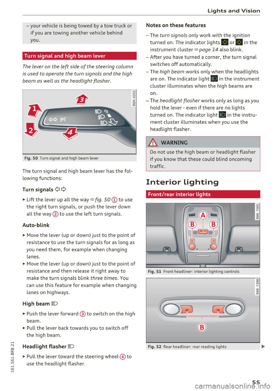
Turn signal and high beam lever
The lever on the le~ side of the steering column
is used to operate the turn signals and the high
beam as well as the headlight flasher.
Fig. SO Tu rn signal and high bea m lever
The turn s ignal and high beam lever has the fol·
lowing functions:
Turn signals ¢¢
8 N
0
~ IXI
• Lift the lever up all the way¢ fig. 50 (D to use
t h e right turn s ignals, or push the lever down
all the way @to use the left turn signals .
Auto-blink
• Move the lever (up or down) just to the point of
resistance to use the turn signa ls for as long as
you need them, for example when changing lanes .
• Move the lever (up or down) just to the point of
resistance and then release it right away to
make the turn s ignals blink
three times. You
can use this feature for example when changing
l anes on highways.
High beam ~D
• Push the lever forward@ to switch on the high
beam.
• Pull the lever back towa rds yo u to switch off
the high beam .
Headlight flasher ~D
• Pull the lever toward the steering wheel© to
u se the head light flasher .
Lights and V ision
Notes on these features
-The turn signals only work w ith the ignition
turned on. The indicato r lights
II or II in the
instr ument cluster ¢
page 14 also blink.
- After you have turned a corner, the turn signa l
switches off automatically.
- The
high beam wo rks on ly when the headlights
are on. The indicator light
II in the instrument
cluster illuminates when the high beams are
on.
- The
headlight flasher works only as long as yo u
hold the lever· even if there are no lights
turned on . The indicator light
II in the instru
ment cluster illuminates when you use the
headlight flasher .
A WARNING
-Do not use the high beam or head light flasher
i f you know that these could blind oncoming
traffic.
Interior lighting
Front /rear interior lights
_. --=:.
I-~~
._ -- v
8 G
o .. .. c
l
Fig. 51 Front head line r: in ter io r light ing cont rols
Fig. 52 Rear headliner: rear read ing lights
55
Page 58 of 300
Lights and Vision
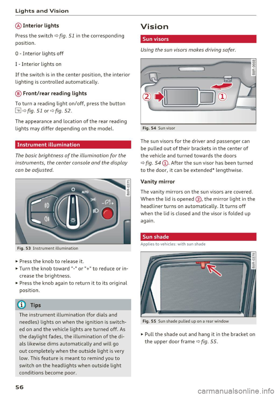
@ Interior lights
Press the switch
~fig. 51 in the co rresponding
position.
0 -Inte rior lights off
I -Interior lights on
If the sw itch is in the center position, the interio r
lighting is controlled automatically.
@ Front /rear reading lights
To tur n a reading light on/off, press the button
@~ fig. 51 or~fig . 52.
The appearance and location of the rea r read ing
lights may differ depending on the model.
Instrument illumination
The basic brightness of the illum ination for the
instruments, the center console and the display
can be adjusted.
Fi g. 53 Instrument illum inat io n
.. Press the knob to release it .
.. Turn the knob toward"-" or" +" to reduce or in
c rease the brightness .
.. Press t he knob again to retu rn it to its original
pos ition.
(D Tips
T he instrument illumination (fo r dials and
needles) lights o n when the ignition is switch
e d on and the ve hicle lights are turned off. As
t he daylight fades, t he illum ina tion of the di
als likewise dims au tomati ca lly and w ill go
out comp letely when the outside light is very
low. This feature is meant to remind you to
sw itch on the head lights when o utside light
conditions become poor.
56
Vision
Sun visors
Using the sun visors makes driving safer .
Fig. 54 Sun v isor
The sun viso rs fo r th e driver and passenger can
be p ulled out of their brackets in the center of
the ve hicle and turned towa rds t he doors
~ fig. 54@. After the s un v isor has been turned
to the door, it can be extended* lengthwise.
Vanity mirror
The van ity mirrors on t he sun visors are covered.
When the lid is opened @, the mi rror light in the
headliner turns on automatically . It turns off
when the lid is closed and the visor is fo lded up
again.
Sun shade
App lies to vehicles, with sun s had e
Fig . 55 Sun shade pulled up on a rear window
.. Pull the shade out and hang it in the bracket on
the upper door frame~
fig. 55.
Page 63 of 300
..... N
co ~ CX)
..... I.Cl U"I
..... I.Cl .....
-If swa llowed and person is conscious, rinse
mouth with water for at least 15 m inutes.
Do not induce vomit ing unless instructed to
do so by medical professional. Get medical
attent ion immed iately.
(D Note
Liquid electrolyte leaking from broken m irror
glass will damage any plastic surfaces it
comes in contact with. C lean up spilled elec
trolyte immediately w ith clean water and a
sponge.
@ Tips
- Switch ing off the dimming function of the
i nside rear v iew mirror also deact ivates the
automat ic dimming function of the exte rior
mir rors*.
- The automatic d imm ing mirrors do not dim
when the interior lighting is turned on or
the reverse gea r is selected .
- Automat ic dimming for the m irror on ly op
erates prope rly if the light str iking the in
s ide mirror is not hinde red by othe r objects.
Digital compass
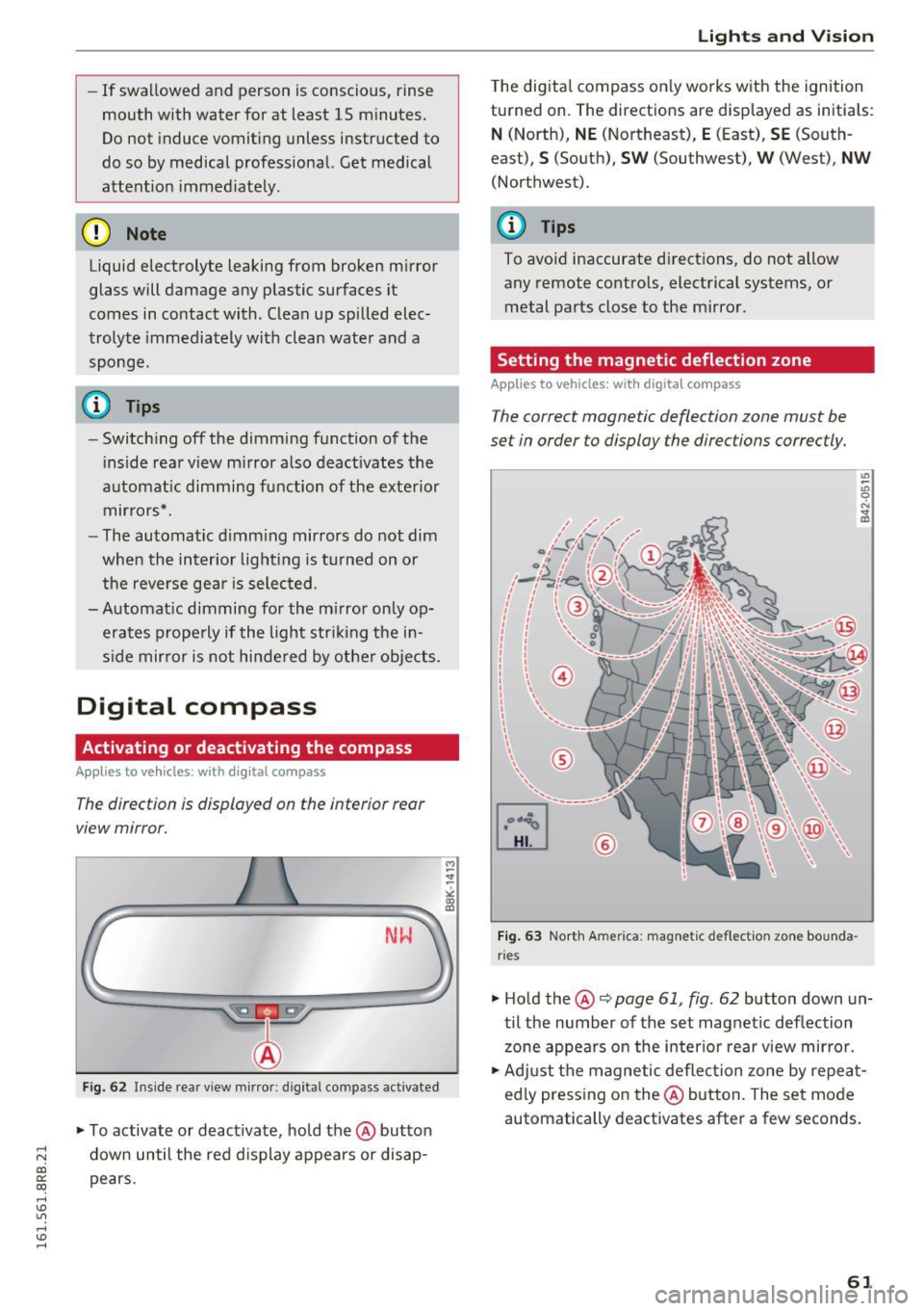
Activating or deactivating the compass
A ppl ies to vehicles: with digital compass
The direction is displayed on the interior rear
view mirror.
Fi g. 62 Inside rea r view m irror: d igital compass activated
... To activate or deactivate, hold the @button
down until the red d isplay appears or disap
pears.
Lights and V ision
The digita l compass on ly works with the ignition
turned on. The directions are disp layed as initia ls :
N (North), NE (Northeast), E (East), SE (South
east),
S (South), S W (Southwest), W (West), NW
(Northwest).
(!_) Tips
To avoid inaccurate d irect ions, do not allow
any remote controls, electrical systems, or
metal parts close to the mirror.
Setting the magnetic deflection zone
App lies to vehicles: wi th digita l co mp ass
The correct magnetic deflection zone must be
set in order to display the directions correctly.
®
F ig . 63 No.rth Ame rica: magnetic deflection zone bounda
ri es
... Hold the@~ page 61, fig . 62 button down un
til the number of the set magnet ic deflection
zone appears on the in ter io r r ear view mirror.
... Adjust the magnetic deflection zone by repea t
ed ly press ing on the@ button. The set mode
automatically deactivates after a few seconds .
61
Page 64 of 300
Lights and Vi sion
Calibrating the compass
Applies to vehicles: with digital compass
The compass has to be recalibrated if the display
is wrong or inaccurate .
.,. Hold the@ button down until the letter C is
displayed on the interior rear view mirror.
.,. Drive in a circle at a speed of about 6 mph (10
km/h) until a d irection is shown on the interior
. . rear view mirror.
A WARNING
The digital compass is to be used as a direc
tional aid only. Even though you may want to
look at it whi le you are driving, you must still
pay attention to traffic, road and weather
conditions as well as other possible hazards.
62
Page 95 of 300
..... N
co ~ CX)
..... I.Cl U"I
..... I.Cl .....
engine will no t be switched off in the following
situations:
- The eng ine has not reached the m in imum re
quired temperature for Start-Stop-mode.
- T he interior temperature selected by the A/C
system has not been reached.
- The outs ide temperatu re is ext remely h igh/low.
- The w indshield is being defrosted
¢ page 82.
-The parking system* is switched on.
- The battery charge level is too low.
- The steering whee l is sharply turned or there is
a steering movement.
- After engaging the reverse gear.
- On sharp inclines .
IIJ appears in the instrument cluster display and
§ii;Ff&Ff ~lso appears in the tr ip comp ute r.
Engine automatically re starts
The stop phase is interrupted in the following sit
uations, for example . The eng ine restarts without
any action by the driver .
- The interior temperature varies from the tem
perature se lected in the A/C system .
- The windshield is beeing defrosted
¢ page 82.
- The brake pedal is pressed several times in a
row.
- The battery charge level becomes too low.
- High power cons umption .
IIJ appears in the instrument cluster display and
H§;Ff&Fii ~lso appears in the tr ip comp ute r.
Switching the ignition off autom atically
To prevent the battery from draining, the ignition
will switch off
automati cally when all of the fol
lowing cond itions have been met:
- The veh icle has already been driven.
- The eng ine has been turned off by the Start-
Stop-System .
- The driver's door is opened .
- T he dr iver's seat bel t is removed.
- The brake pedal is not pressed down.
- T he veh icle is stationary .
In this case, the activated low beam will be re
placed by the s ide marker lights . The side marker
D rivi ng
lights will switch of f after approximate ly 30 m i
nutes or when you lock the veh icle.
If t he Start-S top-System has not turned off the
engine or if you have swi tched the S tart -Stop
System off manually, the ignition will
not be au
tomatica lly switched off and the eng ine wi ll con
t in u e to run¢& .
A WARNING <= -
Never allow the engine to run in confined
spaces -danger of asphyx iation.
(D Tips
If you shift into the 0/S or N positions after
shifting into reverse, the vehicle must be dr iv
en faster than 6 mph (10 km/h) in order for
the engine to switch off again .
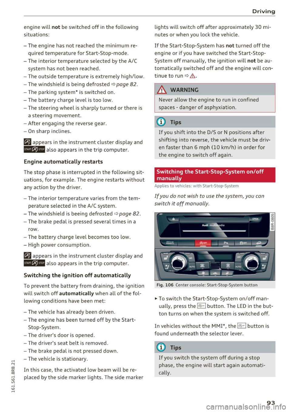
Switching the Start-Stop -System on /off
manually
App lies to vehicles: wi th Start -S top-Syste m
If you do not wish to use the system, you can
switch it off manually.
= , __ (A)Off _ --"'-- f'~-.::a-----
Fig . 10 6 Cen ter co nsole: S ta rt -Stop -System button
.. To switch the Start -Stop-System on/off man
ually, press the
I CAJ ,,.I button. The LED in the b ut
ton turns on when the system is switched off .
In vehicles without the M MI*, the
!CA.> "'! button is
found underneath the se lector lever.
(D Tips
If y ou swit ch the system off d uring a stop
phase, the engine will st art aga in automati
ca lly.
93
Page 198 of 300
Intelligent Technology
electrical energy is not being used than is being
generated and ensures an optimal state of
charge for the battery.
(D Tips
- But even energy management cannot neg ate the limits of physics . Consider that the
power and life of a battery are limited.
- If starting ability is threatened, the indica
tor light (•) appears
r=:; page 33.
What you should know
The highest priority is given to maintaining start
ing capability.
The battery is severely taxed in short-distance
driving, in city traffic and during the cold time of
year. Abundant electrical energy is required, but only a little is generated. It is also critical if the
engine is not running and electrical components
are turned on. In this instance energy is being
consumed but none is being generated.
It is in precisely these situations that you will no
tice energy management actively regulating the
distribution of energy .
Vehicle stands for an extended period
If you do not drive your vehicle over a period of
several days or weeks, electrical components are
gradually cut back or switched off. This reduces
energy consumption and maintains starting ca pability over a longer period. Some of the con
venience functions may not operate, such as the interior lights or the power seat adjustment . The
convenience functions will be available again
when you switch on the ignition and start the en
gine.
With the engine turned off
If you listen to the radio, for example, with the
engine turned off or use other MMI" functions,
the battery is being discharged .
If starting capability is jeopardized due to energy
consumption, a message appears in the radio or MMI* display . The message indicates that the
system will be switched off automat ical ly in a
196
moment. If you wish to continue using the func
tions, you have to start the engine .
With the engine running
Although electrical energy is generated when the
vehicle is being driven, the battery can become
discharged. This happens mostly when little en
ergy is being generated and a great deal con
sumed and the battery's state of charge is not
optimal.
To bring the energy balance back into equilibri
um, consumers which require especially large
amounts of energy are temporarily cut back or
switched off. Heating systems in particular re
quire a great deal of energy. If you notice, for ex
ample, that the heated seats* or the heated rear
window are not heating, they have been tempo
rarily cut back or switched off . These systems will
be available again as soon as the energy balance
has been restored.
You will also notice that engine idle speed has
been increased slightly . This is normal and not a
cause for concern. By increasing engine idle
speed the additional energy required is generat
ed and the battery is charged.
Page 232 of 300
Checking and Filling
Disconnecting the battery terminals
Some vehicle functions (power window regula
tors, for example) are lost if the battery termi
na ls are disconnected. These functions have to be
relearned after the battery terminals are con
nected again. To prevent this, the battery should
only be disconnected from the vehicle e lectrical
system when absolutely necessary for repairs.
Vehicles not driven for long periods
If you do not drive your vehicle over a period of
several days or weeks, electrical components are
gradually cut back or sw itched off. This reduces
energy consumption and ma intains starting ca
pab ility over a longer period
c::> page 195 .
Take into consideration that when you unlock
your veh icle, some convenience functions, such
as the interior lights or the power seat adjust
ment, may not be available. The convenience
functions will be available again when you turn
on the ignition and start the engine.
Winter operation
During the winter months, battery capacity tends
to decrease as temperatures drop. This is be
cause more power is also consumed while start
ing, and the head lights, rear window defogger,
etc., are used more often.
Avoid unnecessary power consumption, particu
larly in city traffic or when traveling only short
d istances . Let your authorized Audi dealer check
the capacity of the vehicle battery befo re winter
sets inc::>
page 231. A well cha rged battery w ill
not only preven t starting problems when the
weather is cold, but will also last longer.
Working on the battery
Be especially careful when working on or near
the battery.
The batte ry is located in the luggage compart
ment under the floor. Before you check anything
in the luggage compartment,
read and heed all
WARNINGS
c::> & .
Hybr id drive*: you can find important information
about the high volta ge battery unde r
c::> page 97.
230
Always heed the safety warnings , when working
on the vehicle battery or the vehicle electrical system to prevent injury.
The following WARNINGS are very important
when working on the battery :
Always heed the following WARNING SYM· BOLS and safety precautions when working on
the battery .
®
Always wear eye protection .
A
Battery acid contains sulfuric acid. Al-
ways wear gloves and eye protection .
@
No
• sparks
• flames
- smoking.
~
When a battery is charged, it produces
hydrogen gas which is explosive and
could cause personal injury.
®
Always keep the battery well out of reach
of children .
.b WARNING
-
Whenever working on the battery or on the
e lectrica l system, there is the risk of injury,
accident and even fire. Read and heed the fol
lowing WARNINGS:
- Always wear eye protection . Do not let bat
tery acid or any lead particles get on your
skin or clothing. Shield your eyes. Explosive
gases can cause blindness or other injury.
- Battery acid contains sulfuric acid. Sulfuric
acid can cause blindness and severe burns.
-A lways wear glo ves and eye protection. Do
not tilt the battery because acid could leak
out of the ventilation openings.
- If you get battery acid in yo ur eyes or on
you r skin, immediate ly rinse with cold wa
ter for several minutes and get medical at
tention .
- If you should ingest any battery acid , seek
medical attention immediate ly.
- Do not expose the battery to an open flame,
elec tric sparks or an open light.
- Do not smoke.
~
Page 273 of 300
..... N
co ~ CX)
..... I.Cl U"I
..... I.Cl .....
When jump starting or charging the bat
tery, never connect the negative ground ca
ble to tbe battery negat ive post because the
battery manager system must be ab le to de
tect the battery's state of charge. Always
connect the negative ground cable to the
negative ground post of the battery manag
er contro l unit .
Use of jumper cables
Make sure to connect the jumper coble clomps in
exactly the order described below!
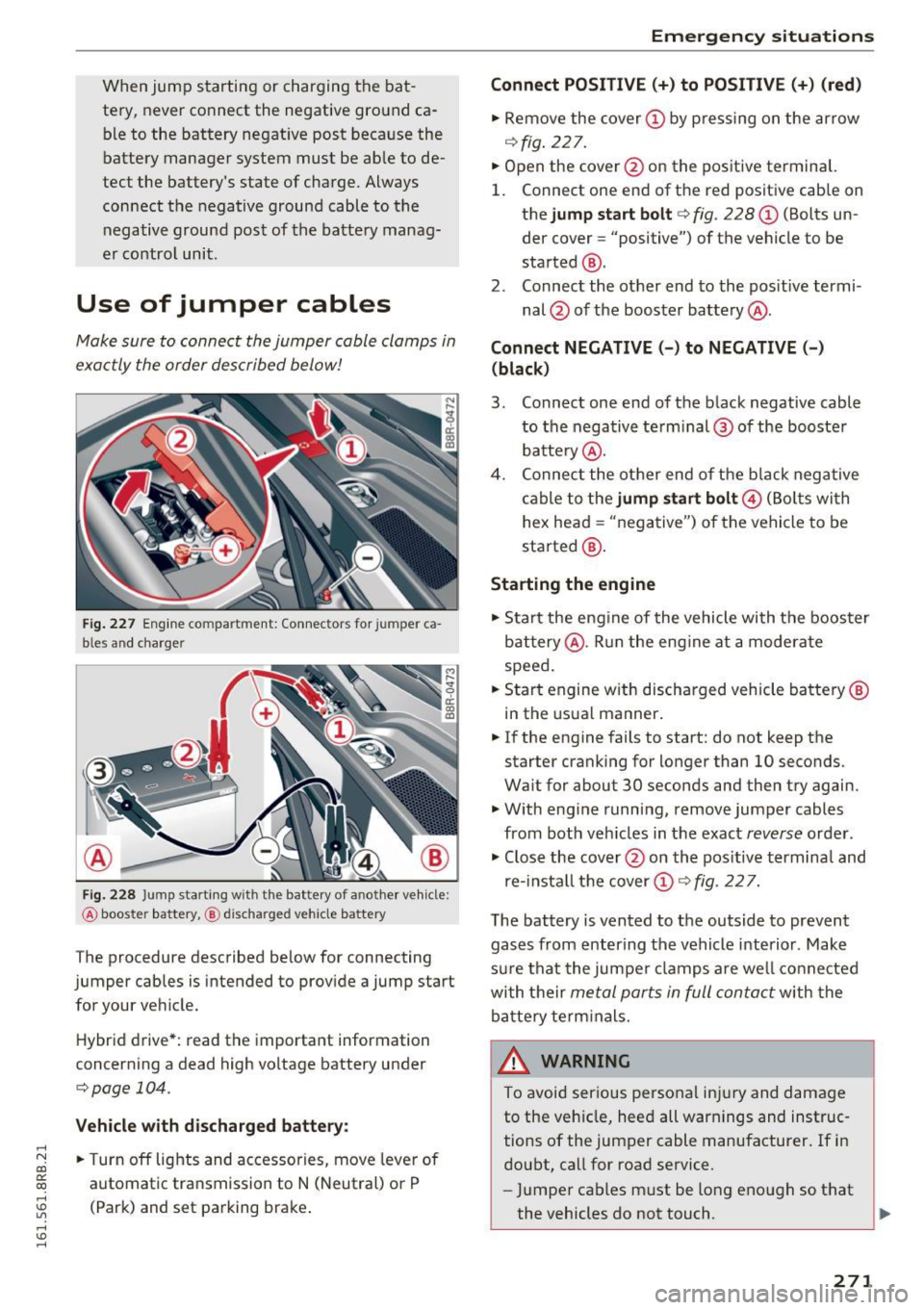
Fig. 227 Engine co mpartment: Connectors for jumper ca
b les and charger
Fig. 228 Jump starting w ith the bat tery of a nother vehicle:
@ booste r battery, @ discha rged veh icle battery
The procedure described below for connecting
jumper cables is intended to provide a jump start for your vehicle.
Hybrid drive*: read the important information
concerning a dead high voltage battery under
c;;,poge 104.
Vehicle with discharged battery:
.. Turn off lights and accessories, move lever of
automatic transmission to N (Neutral) or P
(Park) and set parking brake .
Emergency situations
Connect POSITIVE(+) to POSITIVE (+) (red)
.. Remove the cover@ by pressing on the arrow
¢fig. 227.
.. Open the cover @on the positive terminal.
1. Connect one end of the red positive cab le on
the
jump start bolt r=;;, fig. 228 @ (Bolts un
der cover= "positive") of the vehicle to be
started @.
2. Connect the other end to the positive termi-
nal @ of the booster battery @.
Connect NEGATIVE(-) to NEGATIVE(-)
(black)
3. Connect one end of the black negative cable
to the negative te rm i nal @of the booster
battery @.
4. Connect the other end of the bla ck negative
cable to the
jump start bolt@ (Bolts wi th
hex head = "negative") of the vehicle to be
started @.
Starting the engine
.. Start the engine of the vehicle with the booster
battery @. Run the eng ine at a moderate
speed .
.. Start engine w ith discharged vehicle battery®
in the usual manner .
.. If the engine fails to start: do not keep the
starter cranking for longer than 10 seconds.
Wait for about 30 seconds and then try again .
.. With eng ine running,
remove jumper cables
from both veh icles in the exact
reverse order .
.. Close the
cover @on the positive terminal and
re-install the cover (!)¢
fig. 227.
T he battery is vented to the outside to prevent
gases from entering the vehicle interior . Make
sure that the jumper clamps are well connected
with their
metal ports in full contact with the
battery term inals.
& WARNING ~
To avoid serious personal injury and damage
to the veh icle, heed all warnings and instruc
tions of the jumper cable manufacturer. If in
doubt, call for road
service.
-Jumper cables must be long enough so that
the vehicles do not touch.
~
271
Page 292 of 300
Index
Hill descent control . . . . . . . . . . . . . . . . . . . 125
Home link (garage door opener) . . . . . . . . . . 48
Hood Opening . . . . . . . . . . . . . . . . . . . . . . . . . . . 220
Rele ase lever . . . . . . . . . . . . . . . . . . . . . . . 220
Horn . . . . . . . . . . . . . . . . . . . . . . . . . . . . . . . . . 8
How are child restraint system anchors relat-
ed to child safety . . . . . . . . . . . . . . . . . . . . . 183
How many a irbags doe s my vehicle have? . . 157
How safety belt pretensioners work . . . . . . 149
Hybrid drive. . . . . . . . . . . . . . . . . . . . . . . . . . . 97
12 volt batteries . . . . . . . . . . . . . . . . . . . . 104
Consumption display . . . . . . . . . . . . . . . . . 104
Efficient drive mode . . . . . . . . . . . . . . . . . . 101
Energy flow display . . . . . . . . . . . . . . . . . . 103
EV mode ..... .. ................ .... 100
High voltag e battery .............. 97, 104
High voltage system . . . . . . . . . . . . . . . . . . 97
Operating modes . . . . . . . . . . . . . . . . . . . . 100
Power meter . . . . . . . . . . . . . . . . . . . . . . . . . 98
Starting the vehicle . . . . . . . . . . . . . . . . . . . 98
Transport . . . . . . . . . . . . . . . . . . . . . . . . . . 105
I
Ignition
Switching on/off . . . . . . . . . . . . . . . . . . . . . 84
Ignition k ey
Emergency unlocking . . . . . . . . . . . . . . . . . . 38
I gnition lock . . . . . . . . . . . . . . . . . . . . . . . . . . 84
Malfunction . . . . . . . . . . . . . . . . . . . . . . 30, 34
Imbalance (wheels) . . . . . . . . . . . . . . . . . . . 242
Important things to do before driving . . . . 134
I mproperly worn safety belts . . . . . . . . . . . 149
Indicator lights . . . . . . . . . . . . . . . . . . . . . 14, 99
Airbag system . . . . . . . . . . . . . . . . . . . . . . 161
PASSENGER AIR BAG OFF . . . . . . . . . . . . . 161
Infant seats . . . . . . . . . . . . . . . . . . . . . . . . . 1 76
I nflatable spare tire . . . . . . . . . . . . . . . . . . . 255
Inflating . . . . . . . . . . . . . . . . . . . . . . . . . . . 256
Inflation pressure (tires) . . . . . . . . . . . . . . . 244
Insta lling the upper tether strap on the an
chor age . . . . . . . . . . . . . . . . . . . . . . . . . . . . . 187
I nstrument cluster . . . . . . . . . . . . . . . . . . . . . 98
Indicator lights . . . . . . . . . . . . . . . . . . . . . . 14
Messag es . . . . . . . . . . . . . . . . . . . . . . . . . . . 14
I nstrument illum inat ion . . . . . . . . . . . . . . . . 56
290
Instruments . . . . . . . . . . . . . . . . . . . . . . . . . . 10
Instruments and controls Genera l illustration . . . . . . . . . . . . . . . . . . . . 8
Interior lights Front . . . . . . . . . . . . . . . . . . . . . . . . . . . . . . . 55
Rear . . . . . . . . . . . . . . . . . . . . . . . . . . . . . . . 55
Interval wiping . . . . . . . . . . . . . . . . . . . . . . . . 57
Rain sensor . . . . . . . . . . . . . . . . . . . . . . . . . . 5 7
J
Jump-starting 270
Jumper cables . . . . . . . . . . . . . . . . . . . . . . . . 271
Jump s ta rt ing 104
K
Key..........
.. .. .. .. ............... . 36
Battery replacement . . . . . . . . . . . . . . . . . . 3 7
Check light . . . . . . . . . . . . . . . . . . . . . . . . . . 3 7
Emergency key . . . . . . . . . . . . . . . . . . . . . . . 86
Ignit ion/engine on/off . . . . . . . . . . . . . . . . 84
Key replacement . . . . . . . . . . . . . . . . . . . . . 36
Master key with remote control . . . . . . . . . 36
Mechan ical key. .. .. .. ............. .. . 37
Removing . . . . . . . . . . . . . . . . . . . . . . . . . . . 86
Kick -down
tiptronic . . . . . . . . . . . . . . . . . . . . . . . . . . . 126
L
Lane Change Assistant
refer to Side assist . . . . . . . . . . . . . . . . . . . 115
LATCH . . . . . . . . . . . . . . . . . . . . . . . . . . . . . . 183
Descr iption . . . . . . . . . . . . . . . . . . . . . . . . . 184
Installing a child restraint . . . . . . . . . . . . . 185
Location . . . . . . . . . . . . . . . . . . . . . . . . . . . 184
Mounting and releasing the anchorage
hook . . . . . . . . . . . . . . . . . . . . . . . . . . . . . . 185
Lateral angle .. .. .. .. .. .. ........... .. 201
Leather care/cleaning .. ... .......... .. 210
L eft hand drive . . . . . . . . . . . . . . . . . . . . . . . . 54
Lifting jack . . . . . . . . . . . . . . . . . . . . . . . . . . 261
Light Coming home . . . . . . . . . . . . . . . . . . . . . . . . 53
Dayt ime running l ights . . . . . . . . . . . . . . . . 53
Driving light control. . . . . . . . . . . . . . . . . . . 52
Emergency flashers . . . . . . . . . . . . . . . . . . . 54