reset AUDI Q7 2010 Owner´s Manual
[x] Cancel search | Manufacturer: AUDI, Model Year: 2010, Model line: Q7, Model: AUDI Q7 2010Pages: 390, PDF Size: 93.04 MB
Page 11 of 390
Instruments and controls
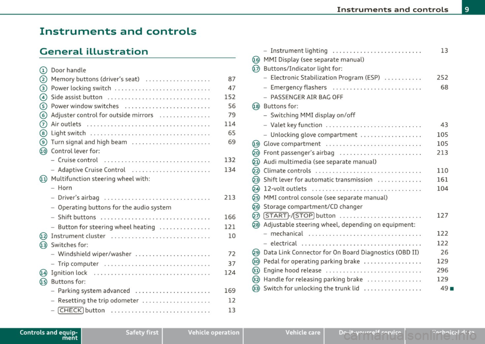
General illustration
(D Door handle
@ Memory buttons (driver's seat) .................. .
@ Power locking sw itch ........................... .
© Side assist button ... .. ... ... ... .. .. .. ... . .. ... .
® Power window sw itches ... .... .. .. .. .. .. ... ... . .
© Adjuster con trol for outs ide mir rors .............. .
0 Air outlets .......... .... .. .... ............... .
@ Light switch ...... .. .... ... .. .. .. ... ... .. .. ... .
® Turn s ignal and high beam ...................... .
@ Control lever for:
- Cru ise control . .... ... ... .. .. .. .. .. .. .. .. ... .
- Adaptive Cruise Control .. .. ................ .. .
@ Mu ltifunction steering wheel with:
- Horn
- Driver's airbag .............................. .
- O pera ti ng butto ns for the audio system
- Shift buttons . ... .. .. .. .... .. .. .. .. .. ...... . .
- Button for steer ing whee l heating ..... ... ...... .
@ Instrument cluster ............................ .
@ Switches for:
- Windshield wiper/washer ... ...... .. ..... .... . .
- Trip computer .............................. .
@ Ignition lock ................................. .
@ Buttons for:
- Par king sys tem advance d .... ..... .. .. ... .. .. . .
- Resetting the trip odometer ................... .
- ICHECK ]button ......................... ... .
Controls and equip
ment Safety first
87
47
1S2 S6
79
1 14
6S
69
132
134
2 13
166
12 1
10
72
37
124
169
12
13
Instruments and controls
- Instrument lighting ......................... .
@ MMI Disp lay (see separate ma nual)
@ Buttons/Indicator light for:
- Electronic Stabilization Program (ESP) .......... .
- Emergency flashers ...... .. ................. .
- PASS ENGER A IR BAG O FF
@ B uttons for:
- Switching MMI d isplay on/off
- Valet key function .. .. .. .. .. .. .. ...... ... .. .. .
- Unlocking g love compartment ................. .
@ Glove compartment ........................... .
@ Front passenger's airbag ...... ..... .. ..... .. .. . .
@ Audi mu ltime dia (see separate man ual)
@ Climate cont rols .............................. .
@ Shift leve r for automatic transmission ............ .
@ 12-volt outlets ............................... .
@ MMI contro l console (see separate manua l)
@ Storage compartment/CD changer
@ ISTART]-/ISTOP] button ....................... .
@ Adjustable stee ring whee l, depending on eq uipme nt:
- mecha nical .... .. .... ... .. .. .. ... .... ..... . .
- electrical ..... . ... .. .. .. .... .... .. .. .. ... .. .
@ Da ta Lin k Connecto r for On Boa rd Diagnos tics (OBD II)
@ Peda l for operating pa rking brake ................ .
@ Engine hood release ............. ... .. ......... .
@ Handle for releasing parking brake ............... .
@ Switch for unlocking the trunk lid ................ .
Vehicle care
13
2S2
68
43
105
105
213
1 10
161
104
127
12 2
122 2 6
129
296 129
49 •
Technical data
Page 12 of 390
Instruments and warning /indicator lights
Instruments and warning/indicator lights
Instruments
Instrument cluster and controls
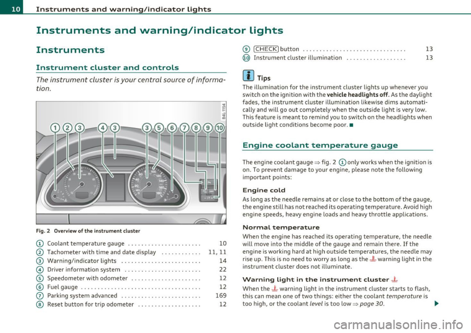
The instrument cluster is your central source of informa
tion.
Fi g. 2 O ver view of th e in stru men t clust er
© Coolant temperature gauge . . . . . . . . . . . . . . . . . . . . . . 10
@ Tachometer with t ime and date d isplay . . . . . . . . . . . . 11, 11
® Warning/indicator lights . . . . . . . . . . . . . . . . . . . . . . . . 14
© Driver information system . . . . . . . . . . . . . . . . . . . . . . . 22
© Speedomete r with odometer . . . . . . . . . . . . . . . . . . . . . 12
© Fuel gauge . . . . . . . . . . . . . . . . . . . . . . . . . . . . . . . . . . . . 12
(j) Park ing system adva nced . . . . . . . . . . . . . . . . . . . . . . . . 169
@ Reset button for trip odometer . . . . . . . . . . . . . . . . . . . 12
@ !CHECK] button .... ...... ..... ......... ...... .
@ Instrument cluster illumination ................. .
(I) Tips 13
1
3
The illum inat ion for the instrument cluster lights up whenever you
switch o n the ignition with the
vehicle headlight s off. As the daylight
fades, the instrument cluste r illum ination likewise d ims automati
cally and w ill go out completely when the outside light is very low .
T his featu re is mean t to remind you to switch on the headligh ts when
outs ide light conditions become poor .•
Engine coolant temperature gauge
The engine coo lant gauge ~ fig . 2 © only works when the ignition is
on. To p revent damage to yo ur engine, ple ase note the following
important po ints:
Engine cold
As long as the needle rema ins at or close to the bottom of the gauge,
t he engine s till has not rea ched its operat ing tem perature. Avo id high
eng ine speeds, heavy eng ine loads and heavy t hrottle app lications.
Normal temperature
When the eng ine has reached its ope rating temperature, the needle
w ill move into the midd le of the gauge and remain t he re.
If the
eng ine is working hard at high outs ide temperatures, the needle may
r ise up. This is no need to worry as long as the
_t_ warning light in th e
instr ument cluster does not illuminate.
Warning light in the instrument cluster -t
When the _L warning light in the instrument cluster starts to flash,
this can mean one of two things: e ithe r th e coolan t
temperature is
too high, or the coolant
level is too low=> page 30. _,.
Page 14 of 390
Instruments and warning /indicator lights
(I) Tips
• T he dig ita l clock and the odomete r are t urned on for about 30
seconds when the driver's door is opened .
• When the ign ition is turned off, the odometer read ing and the
digital clock with date disp lay can be switc hed on for about
30 se conds by press ing the
[CH ECK! button~ page 13, fig. 5. •
Speedometer with odometer
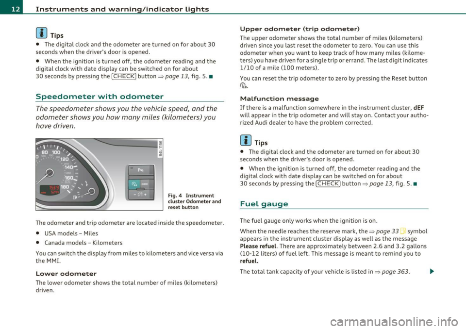
The speedometer shows you the vehicle speed, and the
odometer shows you how many miles (kilometers) you
have driven .
"' ---------1 ~ .!, ;g
Fig. 4 Instrume nt
clu st e r O dom eter a nd
r e se t bu tton
The odometer and tr ip odometer are located inside the speedometer .
• USA models -Miles
• Canada models -Kilometers
You can sw itch the display from miles to kilometers and vice versa via
t he MM I.
Lower odometer
The lowe r odometer shows the total n umber of m iles ( kilomete rs)
dr iven .
Upper odometer (trip odometer)
The upper odometer shows the total n umber of m iles (k ilometers)
dr iven since you last reset the odometer to zero . You can use th is
odometer when you want to keep track of how many m iles (kilome
ters) you have dr iven for a sing le trip or errand. The last d igit indicates
1/10 of a mile (100 meters) .
You can reset t he t rip odometer to zero by pressi ng t he Rese t bu tto n
~ o.o.
Malfunction message
If there is a malfunction somewhere in the instrument cluster, dEF
w ill appear in the tr ip odomete r and will s tay on . Con tact yo ur autho
r ized Audi dealer to have the problem corrected.
[ i ] Tips
• The d igita l clock and the odometer are turned on for about 30
seconds when the driver 's door is opened .
• When the ignition is turned off, the odometer reading and the
dig it a l cl ock with date d isp lay can be sw itched on for abou t
30 seconds by pressing the [
CHECK! button=> page 13, fig. 5. •
Fuel gauge
The fuel gauge only works when the ignition is on.
When the need le reaches the rese rve mark, the~
page 33 symbol
appea rs in the instrument cluste r display as we ll as the message
Plea se refuel. T here are approximate ly between 2.6 and 3.2 gallons
( 1 0-12 li ters) of fuel left . T hi s message is meant to remind you to
refuel.
Th e to tal tank capa city of yo ur vehicle is liste d in ~ page 363.
Page 27 of 390
& WARNING (co ntinued )
• Wo rk with due care when handling the high-volt age section of
gas di scharge (xenon) lights. Failure to do so could result in death
or ser ious injury.
[ i ] Tips
Have the bulb replaced or the connection repaired by your autho rized
Audi Se rvice departmen t.•
Service interval display
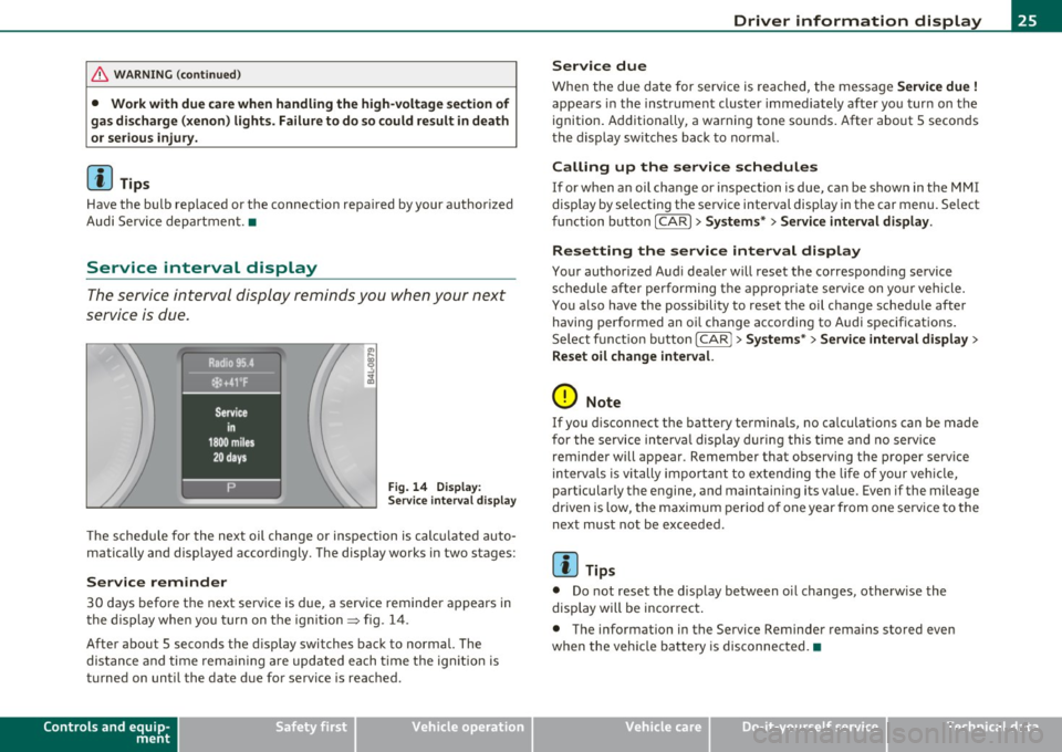
The service interval display reminds you when your next
service is due.
Fig . 14 D ispl ay :
Service inte rval disp la y
Th e schedu le for the next oil change or inspection is c alc ul ated auto
matically and displayed accord ingly. The display works in two stages:
Service reminder
30 days before the next serv ice is due, a serv ice reminder a ppears in
the display when yo u turn on t he ign it ion=> fig. 14 .
After about 5 seconds the d isp lay switches back to normal. The
dis tan ce and time rema ining are updated each t ime t he ig nition is
turned on unti l the date due for service is reac hed .
Controls and equip
ment Safety first
Driver information display
Service due
W
hen the due da te for service is rea ched, t he message Service due !
appea rs in the inst rument cluste r immediately afte r yo u tur n on the
ignition. Additiona lly, a wa rning tone sounds. After about 5 secon ds
the d isp lay sw itches back to no rma l.
Calling up the service schedules
If or when an oil change or inspection is due, can be shown in the MMI
display by se lecting the se rvice interval display in the car menu. Se lect
fu nction button
I CAR ]> Systems *> Service interval display.
Resetting the service interval display
Your authorized Aud i dea ler will reset the correspond ing se rvice
schedule after performing the a ppropriate service on yo ur vehicle .
You a lso have the possibility to reset t he oil c hange sched ule afte r
having performed an o il change acco rding to A udi specifications.
Se lect f unct io n butto n
I CAR j >Systems *> Service interval display >
Reset oil change interval.
0 Note
If you d isconnect the batte ry termina ls, no ca lculations can be made
for the se rvice in terva l display d uring this time and no serv ice
reminder will appear . Remember that observing the proper service
in terv als is vi tally import ant to ex te ndi ng the life of your vehi cle,
particularly the engine, and maintaining its value . Even if the mileage
dr iven is low, the max imum per io d of one year from one serv ice to the
next must not be exceeded.
[I] Tips
• Do not reset the display between oi l changes, otherw ise the
display will be incor rec t.
• The info rmation in the Service Reminder rema ins stored even
when the vehicle ba tte ry is disconnec ted. •
Vehicle care Technical data
Page 38 of 390
Driver information display
Speed warning 1
You can use speed warning 1 to set the maximum speed whi le you are
dr iving. This setting will remain in effect until you turn off the igni
tion , assuming that you have not changed or reset the setting.
Th e speed warning symbol
'8 (USA models) /8 (Canada models) in
the warning 1 display appears when you exceed the maximum speed .
It goes out when the speed falls below the stored maximum speed.
The speed warning symbol will also go out if the speed
exceeds the
stored maximum speed by more than about 2S mph (40 km/h) for at
least 10 seconds . The stored maximum speed is deleted .
Setting speed warning 1
=> page 36.
Speed warning 2
Storing warning 2 is recommended if you a/wayswantto be reminded
of a certa in speed , fo r example when you are traveling in a country
that has a general maximum speed limit, or if you do not want to
exceed a specified speed for winter tires.
The speed warning 2 symbol,
e (USA models)/ 8, (Canada models)
appears in the display when you exceed the stored speed limit. Unlike
warning 1, it will not go out unt il the vehicle speed drops below the
stored speed limit.
Setti ng speed warning 2
=> page 3 7.
[I] Tips
Even though your vehicle is eq uipped w ith a speed war ning system,
you should still watch the speedometer to make sure you are not
dr iving faster than the speed limit.•
Speed warning 1: setting a speed limit
Warning threshold 1 is set by the [ CHECK] button.
Storing the maximum speed
-Drive at the desired maximum speed.
Fig. 19 CHECK button
in the instrument
cluster
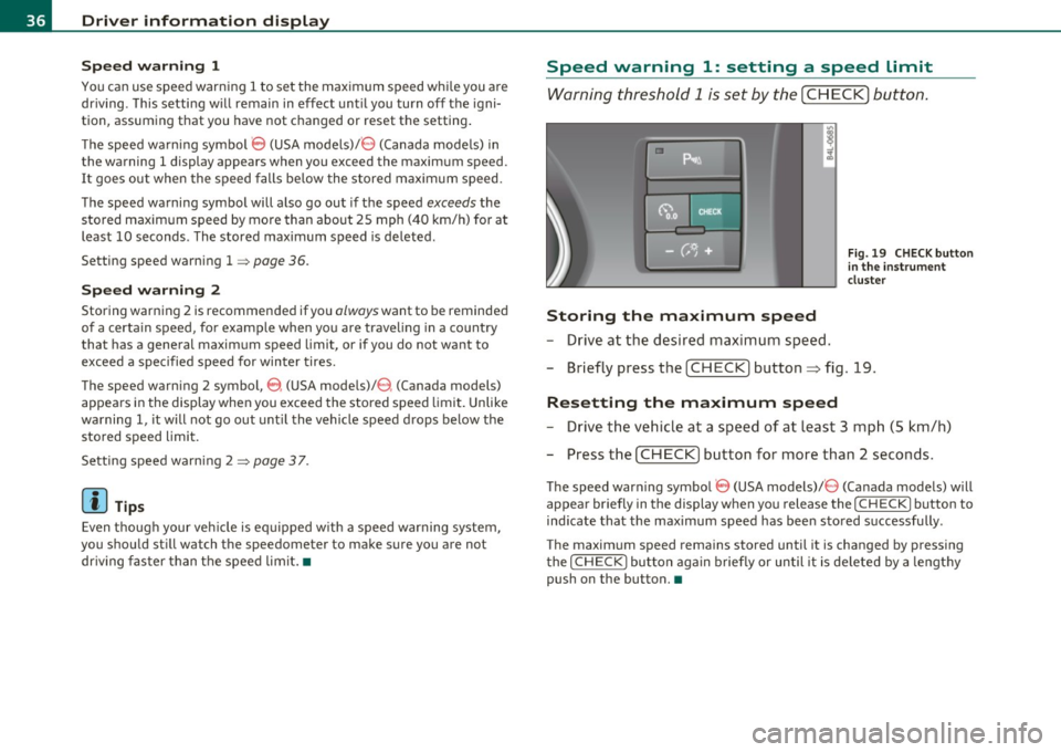
- Briefly press t he [CHECK] button :::;, fig. 19 .
Resetting the maximum speed
-Drive the vehicle at a speed of at least 3 mph (5 km/h)
- Press the
I CHECK ] button for more than 2 seconds.
The speed warning symbol 8 (USA models)/ 8 (Canada models) will
appear briefly in the display when you release the
I CH ECK] button to
ind icate that the maximum speed has been stored successfully .
The maximum speed remains stored until it is changed by pressing
the
I CHECK ] button again briefly or until it is deleted by a lengthy
push on the button. •
Page 39 of 390
![AUDI Q7 2010 Owner´s Manual Speed warning 2: setting a speed limit
Warning threshold 2 is set, changed and deleted in the
fv1fv1I.
- Select: Function button I CAR]> Systems* > Instrument
cluster > Spee d warni AUDI Q7 2010 Owner´s Manual Speed warning 2: setting a speed limit
Warning threshold 2 is set, changed and deleted in the
fv1fv1I.
- Select: Function button I CAR]> Systems* > Instrument
cluster > Spee d warni](/img/6/40275/w960_40275-38.png)
Speed warning 2: setting a speed limit
Warning threshold 2 is set, changed and deleted in the
fv1fv1I.
- Select: Function button I CAR]> Systems* > Instrument
cluster > Spee d warning .
Warning thresho ld 2 can be set in the speed range starting from
20 mph to 150 mph (30 km/h to 240 km/h) . Settings can each be
adjusted in interva ls of 5 mph ( 10 km/h). •
Trip computer
Introduction
The trip computer gives you information on current and
average fuel mileage, average speed, fuel range and
driving time .
Fig. 20 Trip c ompu te r
dis play: Avera g e fue l
m ile ag e
The fo llow ing driving information is continuously ev aluated by the
trip computer and can be displayed sequentially in the instrument
cl uster d isp lay.
Controls and equip
ment Safety first
Dri
ver information display
Fuel rang e
The estimated cruising range in miles (km) appea rs in the display.
T his tells you how far your veh icle w ill be able to travel on the current
tank
of f u e l and with the same dr iv ing style. The display changes in
increments of 6 miles (10 km).
The cruising range is calculated based on the fuel consumption for
t he last 18 miles (30 km). If yo u drive co nse rvat ively, the cruis ing
range will increase.
Average fuel mileage
The average fuel economy in MPG (l/100 km) since you last cleared
t he memo ry appea rs in t his d isp lay. Yo u can use this display to adjust
your dr iv ing techn ique to achieve a desired mileage.
Current fu el mileage
The instantaneous fuel consumption in miles per ga llon (l/100 km) is
show n in this d isp lay. Yo u can use this display to adjust your driving
technique to achieve
a desired m ileage.
Fuel consumption is reca lculated at intervals
of 33 yards (30 mete rs) .
Whe n the vehicle is stat ionary, the most recent fuel consumption is
displayed .
Average speed
The average speed in m ph (km/h) since the last t ime the disp lay was
reset appears i n the display .
Elapsed time
The length of time that you have been driving s ince you last reset the
memory appe ars in this display.
Distance
Th e distance that has been cove red since t he last time the memory
was cleared appears in the display. _,,
Vehicle care Technical data
Page 40 of 390
Driver information display
(I) Tips
• Fuel consumptions (average and current), range and speed are
displayed in metric units on Canadian models .
• All stored values will be lost if the vehicle battery is
disconnected. •
Memories
The trip computer is equipped with two fully automatic
memories.
Fig . 21 T rip comp uter
display: memory level
1
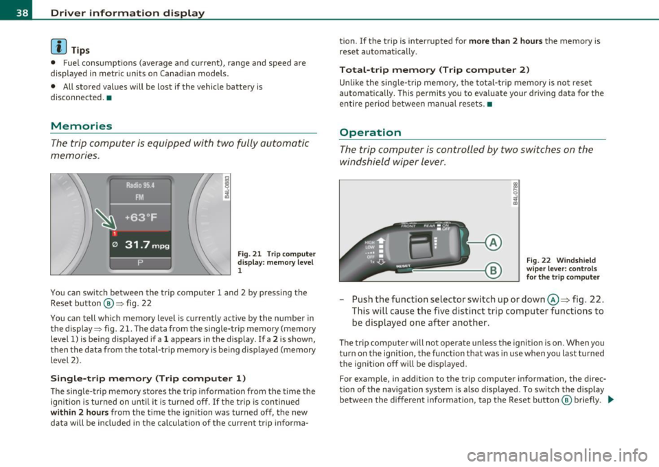
You can switch between the trip computer 1 and 2 by pressing the
Reset button @=> fig. 22
You can tell which memory level is currently active by the number in
the display :::> fig. 21. The data from the single-trip memory (memory
level 1) is being displayed if a
1 appears in the display . If a 2 is shown,
then the data from the total-trip memory is be ing displayed (memory
level 2).
Single-trip memory (Trip computer 1)
The single-trip memory stores the trip information from the time the
ignition is turned on until it is turned off. If the trip is continued
within 2 hours from the time the ignition was turned off, the new
data will be included in the ca lculation of the current tr ip informa - tion. If the trip
is interrupted for
more than 2 hours the memory is
reset automatically.
Total-trip memory (Trip computer 2)
Unlike the single-trip memory, the total-trip memory is not reset
automatically. This permits you to evaluate your driving data for the
entire period be tween manual resets. •
Operation
The trip computer is controlled by two switches on the
windshield wiper lever .
Fig. 22 Windshield
wiper lever: controls
for the trip computer
-Push the function selector switch up or down@~ fig. 22.
This will cause the five distinct trip computer functions to be displayed one after another.
The trip computer will not operate unless the ign ition is on. When you
turn on the ign ition, the function that was in use when yo u last t urned
the ignition off will be displayed .
For example, in addition to the trip computer information, the direc
tion of the navigation system is also displayed . To sw itch the display
between the different information, tap the Reset button ® briefly . .,_
Page 41 of 390
Setting values to zero
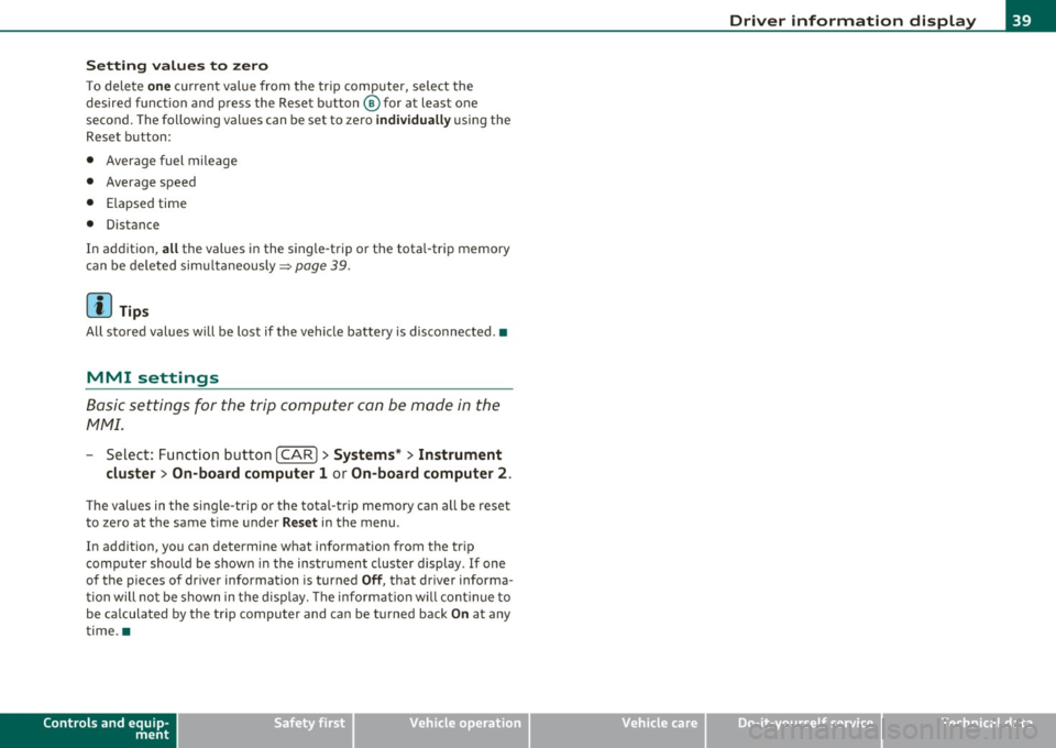
To delete one current va lue from the trip computer, select the
desired funct ion and press the Reset button @for at least one
second. The follow ing values can be set to zero
individually using the
Reset button:
• Average fuel mileage
• Average speed
• Elapsed time
• Distance
In addit ion,
all the values in the single-trip or the total-trip memory
can be deleted simultaneously=>
page 39 .
[ i J Tips
All stored values will be lost if the vehicle battery is disconnected. •
MMI settings
Basic settings for the trip computer can be made in the
MMI.
-Select: Function button I CAR ]> Systems* > Instrument
cluster > On-board computer 1 or On-board computer 2.
The val ues in the single-trip or the total-trip memory can all be reset
to zero at the same time under
Reset in the menu.
In addition, you can determine what information from the trip
computer should be shown in the instrument cluster display . If one
of the p ieces of driver information is turned
Off, that driver informa
tion will not be shown in the display. The in format ion will continue to
be ca lculated by the trip computer and can be turned back
On at any
time. •
Controls and equip
ment Safety first
Driver information display
Vehicle care
Technical data
Page 67 of 390

Clear vision
Lights
Switching the headlights on and off -'t!-
In the "AUTO" position, a light sensor* automatically
swit ches the head- and tai llights on and off in response
to light condition s.
F ig . 5 3 Inst rum ent
pan el: li ght swit ch
The light switch must not be overturned past the stops in
either direction.
Switching on automatic headlight control
-Turn the light swi tch to AUTO ::::, fig. 53.
Switching on the side marker lights
-Tur n the light sw itch to 300~.
Switching on the headlights and high beam
- Turn the light swi tch to ~D.
- Push the high beam lever forward towards the instrume nt
panel=>
page 69.
Con tro ls a nd e quip
m en t Vehicle
OP-eration
Switching off the lights
-Turn the lig ht swit ch to 0.
Clear vision
The headligh ts only work when the ignition is switched on. Whi le
sta rting the engine or when switchi ng off the ignition, the headlights
will go off and o nly the s ide marker lights will be on.
After start ing th e engine, the headlights are automatically adjusted*
to the load and a ng le of the vehicle (fo r example, during acceleration,
braking) . This prevents oncoming traffic from experiencing unneces
sary head light glare from your head lig hts.
If the system is not operati ng p roperly, a warning symbol in t he Auto
Check Control is displayed =>
page 34.
With the side marker lights o r headlights switched on, the symbol
next to the light switch illuminates
coo:.
Daytime running lights
• USA models: The daytime running lights w ill come on automati
ca lly when the ign ition is turned on and the light switch => fig. 53 is
in the
O position or the AUTO position (only in daylight conditions).
Th e
Daytime running light s function can be tu rned on and off in the
MMI menu
Exterior lighting=> page 66.
• Canada model s: The d ay time r unning ligh ts w ill come on a uto
matically when the ig nitio n is turned on and the light switch=> fig. 53
is in the
O pos itio n or the AUTO position (on ly in daylight conditions)
=> & .
Automatic headlight control *
In the switch pos ition AUTO t h e automatic headlight control is
tu rned on. The low beams and tail lights a re turned on au tomatically
throug h a light sensor as soon as ambient br ightness (e .g . when
driving into a tunnel) falls below a va lue preset at the factory . When
amb ient b rightness increases again, the low beams are turned off
again automatically =>& . ..,_
Vehicle care Do-it-yourselt service iTechnical data
Page 111 of 390

_______________________________________________ w __ a _r _m _ a_ n_d _ c_o _ l_ d __ _
Warm and cold
Climate control
Description
The air conditioner is fully automatic and is designed to
maintain a comfortable and uniform climate inside the
vehicle.
We recommend the following settings:
- Set the temperature to 72
°F (+22 °C).
- Press the
[AUTO] button.
With this setting, you attain maximum comfort in the least amount
of time. Change this setting , as desired , to meet your personal needs.
The climate controls are a combination of heating, ventilation and cooling systems, which automatically reduce humidity and cool the
air inside your vehicle .
The air temperature, air flow and air distribution are automatically regulated to achieve and maintain the desired passenger compart
ment temperature as quickly as possible.
The system automatically compensates for changes in outside
temperature and for the intensity of the sunlight entering the
vehicle. We recommend you use the
Automatic mode ~ page 112
for year-round comfort .
Please note the following:
Turn on the air conditioner to reduce humidity in the vehicle. This also
prevents the windows from fogging up.
When the outside temperature is high and the air is very humid,
condensation from the evaporator may drip under the vehicle . This is
normal and does not indicate a leak.
Controls and equip
ment Safety first
If the outside temperature is
low, the fan normally only switches to a
higher speed once the engine coolant has warmed up sufficiently .
The air conditioner temporarily switches off when you drive off from
a standstill using full throttle to save engine power.
The compressor also switches off if the coolant temperature is too
high, so that the engine can be adequately cooled under extreme
loads.
Air pollutants filter
The air pollutants filter (a combined particle filter and activated char
coal filter) reduces or prevents outside air pollution (dust, or pollen)
from entering the vehicle. The air is also filtered in air recirculation
mode.
The air pollutants filter must be changed at the intervals specified in
your Warranty
& Maintenance booklet, so that the air conditioner can
properly work.
If you drive your vehicle in an area with high air pollution, the filter
may need to be changed more frequently than specified in your Audi
Warranty
& Maintenance booklet. If in doubt, ask your authorized
Audi Service Advisor for advice .
Key coded settings
The air conditioner settings selected are automatically stored and
assigned to the key being used. When the vehicle is started, the air
conditioner automatically selects the settings assigned to that key.
This way every driver will maintain his/her own personal settings and
does not have to reset them manually.
If a different driver uses your key and changes the air conditioner
settings, the latest adjustments will erase and replace the settings
you have stored. _.,
Vehicle care Technical data