clock AUDI Q7 2012 Owner´s Manual
[x] Cancel search | Manufacturer: AUDI, Model Year: 2012, Model line: Q7, Model: AUDI Q7 2012Pages: 342, PDF Size: 86.42 MB
Page 268 of 342
266 Check ing and filling
For year-round driving, antifreeze is added at
the factory for temperatures down to:
- -31°F(-35°C)USA
- - 40 °F ( - 40 °C) Canada.
_& WARNING
-
Before you check anything in the engine
compartment, always read and heed all
WARN INGS
¢ .&. in Working in the engine
compartment on page 258.
(D Note
- Befo re winter se ts in, have the coolant
checked to see if t he coolant addit ive in
your vehicle is sufficient to meet the cli
mate conditions. This is especially impor
tant if you live in a region where the win
ter is extremely co ld. If necessary, in
crease the proport ion of coolant additive
to 60%.
- When adding coolant additive to your
cooling system, remember:
- We recommend using only coolant ad ditive G12++ or G13 for your vehicle.
Th is coo lant add itive is available at au
thorized Audi dealers. Other types of
antifreeze can significantly reduce cor
rosion protection. The resulting corro
sion can cause a loss of coo lant and se
r ious engine damage.
- Do not add any type of radiator leak sea l
ant to your vehicle's engine coolant.
Adding rad iator repair fluid may adve rse
ly affect the function and performance of
your cooling system and could result in
damage not covered by your New Vehicle Limited Wa rranty.
Checking the engine coolant level
The engine coolant level can be checked with
a quick glance .
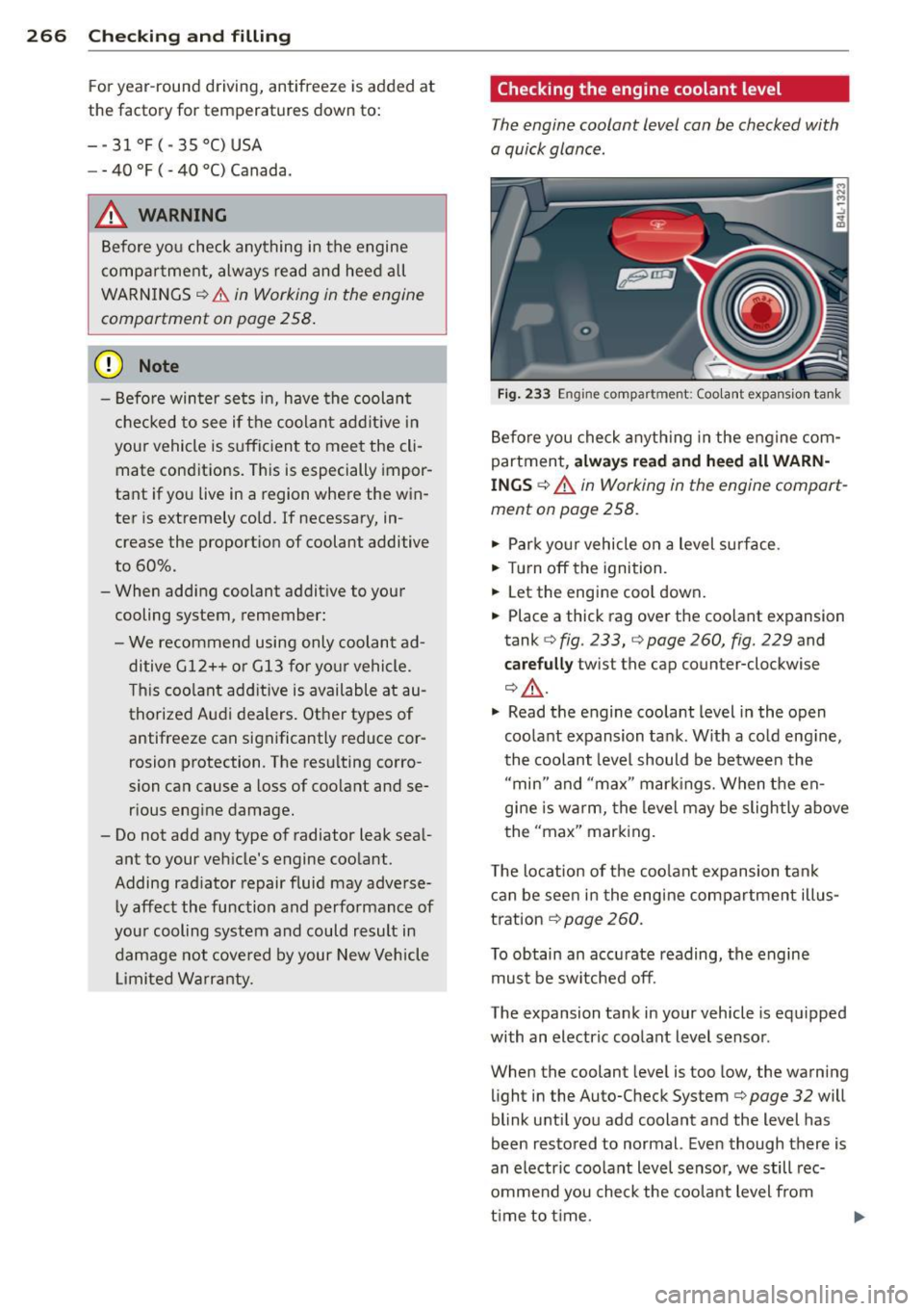
Fig . 233 Engine compartment : Coo lant expansio n ta nk
Before you check a nyth ing in the engine com
partment,
alw ays re ad and h eed all WARN
INGS ¢ A in Working in the engine compart
ment on page 258.
.,. Park yo ur vehicle on a level surface.
.,. Turn off the ignition.
.,. Let the engine cool down.
.,. Place a thick rag over the coolant expansion
tank ¢
fig. 233, c> page 260, fig. 229 and
care full y twist the cap counter-clockwise
¢,&. .
.,. Read the engine coolant level in the open
coolant expansion tank. W ith a cold eng ine,
the coolant level should be between the "min" and "max" markings. When the en
g ine is wa rm, the level may be slightly above
the "max" mark ing.
T he locat ion of the coolant expansion tank
can be seen in the engine compartment illus
tration
¢ page 260.
To obtain an accu rate reading, the engine
must be switched off.
The expansion tank in your vehicle is equipped
with an electric coolant level sensor.
When the coolant level is too low, the warning
light in the Auto-Check System¢
page 32 will
blink until you add coolant and the level has
been restored to normal. Even though there is
an electric coo lant level sensor, we still rec
ommend you check the coolant level from
time to t ime.
Page 269 of 342
Coolant loss
Coolant loss may indicate a leak in the cool ing
system . In the event of coolant loss, the cool
ing system should be inspected immediately
by your authorized Audi d ealer. It is not
enough merely to add coolant.
I n a
sea led system, losses can occur only if
the boiling point of the coolant is exceeded as
a result of overheating.
A WARNING
The cooling system is under pressure and can get very hot. Reduce the risk of scald
ing from hot coolant by following these
steps.
- Turn off the engine and allow it to coo l
down.
- Protect your face, hands and arms from
escaping fluid and steam by covering the
cap with a large, thick rag .
- Turn the cap slowly and very carefully in
a counter -clockwise direction wh ile ap
plying light, downward pressure on the
top of the cap .
- To avoid be ing burned, do not spill ant i
freeze or coolant on the exhaust system
o r hot eng ine parts. Under certai n condi
t ions, the ethy lene g lycol i n engine cool
an t ca n ca tch fire.
(D Note
Do not add any type of rad iator leak seal
ant to you r vehicle's eng ine coolant. Add
ing radiator repair f luid may adversely af
fec t the function and pe rformance of your
cooling system and could res ult in damage
not covered by your New Vehicle Limited
Warranty .
Adding coolant
Be very careful when adding engine coolant.
Before you check anything in the engi ne com
partment ,
alwa ys read and heed all WARN
INGS c:> A in Working in the engine compart
ment on page 258 .
Checking and fillin g 267
.. Turn off the engine .
.. Let the engine coo l down .
.. Place a thick rag over the coo lant expansion
tank
c:> page 266 , fig . 233 and carefully
twis t the cap coun ter-clockwise c:> &, .
.. Add coo lant .
.. Twist the cap on aga in
tightly.
Rep lacemen t engine coolant must conform to
exact spec ificat ions
c:> page 265, Coolant . We
recommend us ing on ly coo lant additive G12+
+, G 13 or in an eme rgency G12 +. Do
not use a
different additive. In an emergency use pla in
water until you can ge t the co rrect addi tive
and can restore the correc t ratio. This sho uld
be done as soon as possible.
If you have lost a cons iderab le amount of
coolant , the n you sho uld add cold ant ifree ze
and cold wate r on ly when the engine is cold.
Always use
n ew engine coolant when refilling .
Do not f ill coolant above the "MAX" mark. Ex
cess coola nt will be forced out through the
pressure relief valve in the cap when the en
gine becomes hot .
A WARNING
- The cooling system is under pressure and
can get ve ry hot. Reduce the risk of
scalding from hot coolan t by following
these steps.
- Turn off the engine and allow it to coo l
down .
- Protect your face, hands and arms from
escaping fluid and steam by covering
the cap w ith a large, th ick rag .
- Turn the cap s lowly and very carefully
i n a counter-clockwise direction while
applying light, downward pressure on
the top of the cap.
- To avoid being burned, do not spill a n
tifreeze o r coolant on the exhaust sys
tem or hot engi ne pa rts. Under certain
c ond it ions, the ethy lene glycol in en
gine coolant c an catch fire .
- Antifree ze is po isonous. Always s to re an
tifree ze in its o rigina l container and well
ou t of the rea ch of child ren. .,.
•
•
Page 283 of 342
pressure label lists the recommended cold
tire i nflatio n pressures for the vehicle at its
maximum capacity we ight a nd the tires that
were on your vehicle at the time it was man
ufactured . For recommended t ire pressures
for normal load condit ions, please see chap
ter ~
page 2 78 .
-Turn the valve stem cap counter-clockwise
to remove it from the tire valve .
- Place the air pressure gauge on the valve.
- The tire pressures should only be checked
and adjusted when the tires are cold . The
s light ly raised pressures of warm tires must
not be reduced .
- Adjust the tire pressure to the load you are
carrying.
- Re insta ll the va lve stem cap on the valve .
When should I check the tire pressure ?
The correct tire pressure is especially impor
tant at high speeds . The pressure sho uld
therefo re be checked at least once a month
and a lways before start ing a journey. Do not
forget to check the tire pressure for the spare
wheel.
When should I adju st the tire pre ssures?
Ad just the tire pressure to the load you are
carrying. After changing a wheel
or replacing
wheels you have to adjust the tire pressures
on all wheels. In addition, you must then
store the new tire pressures i n the t ire pres
sure mon itor ing system
~ page 294.
A WARNING
Incorrect tire pressures and/or unde rinfla
tion ca n lead sudden tire failure, loss of
cont ro l, col lision, ser ious persona l inju ry
or even death.
- Whe n the wa rning symbo l
RI] appears in
the instrument cl uster, s top an d inspect
the tires.
- Incorre ct tire pressure and/or unde rinfla
t ion can cause inc reased t ire wear and
can affect the handling o f the veh icle and
stopp ing ability.
- Incorrect tire pressures and/or underin
flation can also lead to sud den tire fa il-
Tires an d wheel s 281
ure, including a blowout and sudden de
flation, ca using loss of veh icle contro l.
- The driver is responsib le for the correct
tire pressures for all tires on the veh icle.
The applicable pressure values are locat
ed on a sticker o n the dr iver's s ide B-pil
lar .
- Onl y when all tires on the vehicle are fil
led to the correct pressure, the t ire pres
sure mon itor ing system can work cor
rectly .
- The use of incorrect tire pressure va lues
can lead to acc idents or other damage .
Therefore it is ess ential that th e drive r
observe t he spec ified t ire p ress ure val ues
for the tires and the cor rect pressures for
the func tion of the t i re p ress ure moni to r
ing system.
- Always in flate tires to the recommen ded
a nd correct t ire p ress ure be fore dr iv ing
off .
- D riving with unde rinf lated tires bend
mo re, letting them get too hot resulting
in tread separation, s udden tire failure
and loss of control.
- Excessive speed and/overloading can
cause heat b uild- up, sudden tire failure
and loss of control.
- If the tire pressure is too low or too high,
the t ires will wear prematurely and the
veh icle w ill not handle well.
- If the tire is not flat and you do not have
to change a wheel immediately, d rive at
red uced speed to the nearest service sta
tion to check the t ire press ure and add
air as requ ired .
(D Note
Driving w ithout valve stem caps can cause
damage to the tire valves. To prevent this,
a lways make sure that factory installed
valve s tem caps o n all whee ls are sec urely
mounted o n the valve .
@ For the sake of the environment
Underinflated tires will also increase the
fuel consumpt ion.
•
•
Page 298 of 342
2 96 What do I do now ?
plate. If this happens, the vehicle may
start to move while a wheel is being changed.
- Never use the folding chocks if they are
damaged or if they have not been assem
bled correctly.
A WARNING
Improper use of the vehicle jack can cause
ser ious persona l injuries.
- Never use the jack supplied with your Au
di on anothe r vehicle, pa rticularly on a
heavier one. The jack is only suitable for
use on the vehicle it came w ith.
- Us ing a bumper jack to raise the vehicle
will damage the bump er system. The
jack may slip, causing in jury.
- Never support your veh icle on cinder
blocks, b ricks or other objec ts. These
may no t be ab le to suppor t the load and
c ou ld cau se injury whe n they fail.
- Never start o r run the engine while the
vehicle is supported by the j ack.
- If you must wo rk under the vehicle, al
ways use safety stands specifically de
signed for this purpose.
- Always make su re the inf latable spare
ti re and even a flat tire a re se cu red in
pla ce and not loose, otherwise t hey
c ou ld f ly forward, causing personal in jury
to passengers in the veh icle in an acc i
dent o r sudden mane uver.
Removing bass box
Applies to vehicles: with bass box
Before the inflatable spare tire can be taken
out, the bass box must be removed .
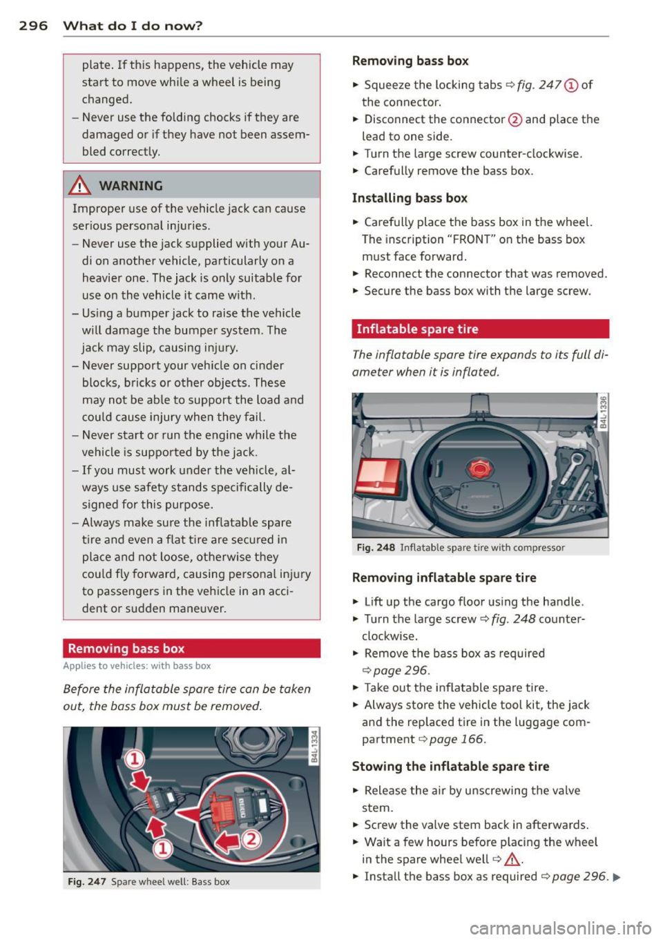
Fig. 247 Spare wheel well: Bass box
Removing bass box
" Squee ze the locking tabs ¢ fig. 247 (!) of
the connector .
" Disconnect the connector @and place the
lead to one side.
" Turn t he large screw counter-clockwise.
" Carefully
remove the bass box.
Installing bass bo x
" Carefully place the bass box in the wheel.
The insc ription " FRO NT" on the bass box
m ust face forward .
" Reconnect the connector that was removed.
" Secure the bass box with t he large screw.
· Inflatable spare tire
The inflatable spare tire expands to its full di
ameter when it is inflated.
Fi g. 2 48 In flatable spare t ire w ith compressor
Removing inflatable spare tire
" Lift up the cargo floor us ing the handle .
" Tu rn the large screw¢
fig. 248 co unter-
clockwise.
" Remove the bass box as required
¢page 296.
" Take out the inflatable spare tire .
" Always sto re the vehicle tool kit, the jack
and the replaced tire in the luggage com
partment
¢page 166.
Stowing the inflatable spar e tire
" Release the air by unscrewing the valve
stem.
" Screw the
valve stem back in afterwards .
" Wait a few hours befo re p lacing the wheel
in the spare whee l we ll
r=:, _.&.
" Install the bass box as required r=:, page 296 . ..,.
Page 302 of 342

300 What do I do now?
Loosening
.,. Install the wheel bolt wrench over the
wheel bolt and push it down as far as it will
go .
.,. Take tight hold of the
end of the wrench
handle and turn the wheel bolts
counter
clockwise
about one single turn in the direc
tion of arrow
c> fig. 251.
Tightening
.,. Install the wheel bolt wrench over the
wheel bolt and push it down as far as it will
go .
.,. Take tight hold of the
end of the wrench
handle and turn each wheel bolt
clockwise
until it is seated .
A WARNING
- Do not use force or hurry when changing
a wheel - you can cause the vehicle to slip
off the jack and cause serious personal
injuries.
- Do not loosen the wheel bolts more than
one turn
before you raise the vehicle with
the jack. - You risk an injury.
@ Tips
If a wheel bolt is very tight, you may find it
easier to loosen by carefully pushing down
on the end of the wheel bolt wrench with
one foot only. As you do so, hold on to the
car to keep your balance and take care not
to slip.
Raising the vehicle
The vehicle must be lifted with the jack first
before the wheel can be removed.
Fig. 252 Sill pane ls: mar kings
Fig. 253 Sill: posit ioning the jack
.,. Activate the vehicle jack mode* (only vehi
cles with Adaptive Air Suspension)
<::> page 154.
.,. Engage the parking brake to prevent your
vehicle from rolling unintentionally
.,. Move the
selector lever to position P .
.,. Find the marking (imprint) on the sill that
is nearest the wheel that will be changed
c> fig. 252. Behind the marking, there is a
lifting point on the sill for the jack.
.,. Turn the
jack located under the lifting point
on the sill to raise the jack until its arm@
c> fig. 253 is located under the designated
plastic mount
c> & c::> (D .
.,. Align the jack so that its arm @ c::> fig. 253
engages in the designated lifting point in
the door sill and the movable base® lies
flat on the ground. The base @ must be
ver
tical
under the lifting point@.
.,. Wind the jack up further until the flat tire
comes off the ground
c> ,& .
Position the jack only under the designated
lifting points on the sill
c>fig . 252. There is
exactly
one location for each wheel. The jack
must not be positioned at any other location
c> .&. c> CD.
An unstable surface under the jack can cause
the vehicle to slip off the jack. Always provide
a firm base for the jack on the ground. If nec
essary place a sturdy board or similar support under the jack . On
hard, slippery surfaces
(such as tiles) use a rubber mat or similar to
prevent the jack from slipping
c> ,&.. liJI,
Page 303 of 342

_& WARNING
-You or your passengers could be injured
while changing a wheel if you do not
follow these safety precautions:
- Position the jack only at the designated
lifting points and align the jack. Other
wise, the jack could slip and cause an
injury if it does not have sufficient hold
on the vehicle.
- A soft or unstable surface under the
jack may cause the vehicle to slip off the jack. Always provide a firm base for
the jack on the ground . If necessary,
use a sturdy board under the jack.
- On hard, slippery surface (such as tiles)
use a rubber mat or similar to prevent
the jack from slipping .
- To help prevent injury to yourself and
your passengers:
- Do not raise the vehicle until you are
sure the jack is securely engaged.
- Passengers must not remain in the ve
hicle when it is jacked up.
- Make sure that passengers wait in a
safe place away from the vehicle and
well away from the road and traffic.
- Make sure jack position is correct, ad
just as necessary and then continue to
raise the jack.
(D Note
Do not lift the vehicle by the sill. Position
the jack only at the designated lifting
points on the sill. Otherwise, your vehicle
will be damaged.
What do I do now? 301
Taking the wheel off/installing the inflatable spare tire
Follow these instructions step-by-step for
changing the wheel
Fig. 254 Chan ging a wh eel : ali gnment p in inside the
t op hole
After you have loosened all wheel bolts and
raised the vehicle off the ground, remove and
replace the wheel as follows :
Removing the wheel
.. Remove the topmost wheel bolt comple tely
and set it aside on a
clean surface .
.. Screw the threaded end of the
alignment
pin from the tool kit hand-tight into the
empty bolt hole
~ fig . 254.
.. Then remove the other wheel bolts as de
scribed above.
.. Take off the wheel leaving the alignment
pin in the bolt hole
~ 0.
Putting on the inflatable spare tire
.. Inflate the inflatable spare tire~ page 297
and push the wheel over the alignment pin.
.,. Screw in and tighten all wheel bolts
slight
ly.
.. Remove the alignment pin and insert and
tighten the remaining wheel bolt slightly
like the rest .
.. Turn the jack handle counter-clockwise to
lower the vehicle until the jack is fully re
leased .
.,. Use the wheel bolt wrench to tighten all
wheel bolts firmly
~page 299 . Tighten
them
crosswise, from one bolt to the (ap
proximately) opposite one, to keep the
wheel centered.
Page 329 of 342
LA T CH sys tem ....... ..... .. .. .. ... 215
Safety instructions ..... ... .. .. .. .. . 203
C hi ld seats
L ower ancho rages ........ .. .. .. .. . 213
C lea ning
A lcantara (synthet ic suede) ..... ... .. 247
Eng ine compartment ........... .... 248
E xhaust tail p ipes ......... .. .. .. .. . 244
F ab rics and fabr ic coverings .. .. .. .. . 245
I ns trumen t panel ......... .. .. .. .. . 24 5
I nterior . . . . . . . . . . . . . . . . . . . . . . . . . . 24 4
L eather .... .. ... ..... ... .. .. .. ... 247
MMI contro l conso le ... ... .. .. .. .. . 244
MMI display ............. .... .. .. . 244
P lastic and v inyl .......... .. .. .. ... 242
P lastic parts
Safety belts 245
248
tr im str ips . ................ ... ... 242
Trim str ips . ............. .... .. .. . 242
Cleaning and protection ..... .. .. .. .. . 239
Climate con trol . . . . . . . . . . . . . . . . . . . . . . 91
Synchronizing .... ..... ... .. .. .. .... 92
Warm and cold . ....... ... .. .. .. .... 91
Clima te con trols
A ir cond itione r o n/off ..... .. .. .. .. .. 93
A ir dist ribution . .. ..... ... .. .. .. .... 94
A ir outlets ... .... .... ... .. .. .. .... 96
Air outlets (rear) . ..... ... .. .. .. .. .. 96
A ir rec irculation .......... .. .. .. .... 95
AUTO (standard setting) . . . . . . . . . . . . . 94
Basic settings . . . . . . . . . . . . . . . . . . . . . . 99
Controls ................... ... ... . 92
D efrosting/defogging . . . . . . . . . . . . . . . 94
D escr ipt io n ... ........... .. .. .. .... 9 1
E ne rgy management ...... .. .. .. .. .. 9 1
F a n ... .. .. .... ............. .. .. .. 94
Fr ont seat vent ilation .. ... .. .. .. .. . 100
Heated seats, front .... ... .. .. .. .. . 100
Key coded setting . ..... ... .. .. .. .. .. 91
Recirculation mode (automatic) . . . . . . . 99
Recommended sett ings .... .. .. .. .. .. 91
Residua l heat ............. ... ... ... 93
Sett ing t he temperature ........ .... . 94
Supp lementary heater ..... .. .. .. .. . 100
Synchron izat ion . . . . . . . . . . . . . . . . . . . . 99
T u rn ing o n and off ........ .. .. .. .. .. 93
Using climate cont rol economically . . . . 9 7
Clock ..... ... ...... ............. ... 11
Inde x 327
Closing
Pano ramic s liding sunroof . . . . . . . . . . . . 55
Coat hoo ks . .. .. .. ................. . 89
Cold t ire inflation pressure ........ .. .. 278
Compass mir ro r . . . . . . . . . . . . . . . . . . . . . 69
Compliance . .. .. .... ... ....... ..... 322
Consumer Information . . . . . . . . . . 167,319
Contacting NHTSA . ............. .. .. 16 7
Convenience key . . . . . . . . . . . . . . . . . . . . . 49
D river messages .. .. .. .. ...... .... . 108
Locking vehicle . . . . . . . . . . . . . . . . . . . . . 50
START butto n .. .. .... ........... .. 10 7
Star ting engi ne ................... 107
STOP butt on ... .. .. . .............. 108
S wi tching engine off . .. ..... ... .. .. 108
Switching on ignition . .. ..... ... .. .. 107
U nlocking vehicle .... .. ..... ... .. .. . 49
Co nve rtib le child safety se ats ..... .. .. 206
Convertib le locking retractor
Activating ....... .. ............... 211
Deact ivating . .. .... .. .. ...... ..... 212
U sing to secure a child safety seat 2.09, 211
Coolant system .. .. ................. 265
Cooling box in glove compa rtment ... .. . 88
Cooling System Expansion tank ... .. ............... 266
Cornering light . . . . . . . . . . . . . . . . . . . . . . 59
C ruise cont ro l
Changi ng speed ..... .. ..... ... .. .. 112
Presett ing your speed .. ..... ... .. .. 112
Switching off . ..... . .. .. ..... ... .. 112
Switching on ... .. ................. 111
Warning/ind icator lights .......... .. . 18
also refer to Adaptive c ruise control . .. 113
Cruising range . . . . . . . . . . . . . . . . . . . . . . . 24
(upholder . . . . . . . . . . . . . . . . . . . 78, 85, 86
D
Damp ing
refer to Adapt ive A ir Suspens ion . 150, 152
Data ......... .. .. .... ............. 316
Data recorder . . . . . . . . . . . . . . . . . . . . . . 219
Date d is p lay . . . . . . . . . . . . . . . . . . . . . . . . 11
Daytime running lights. .. ..... ... . 57, 58
•
•
Page 330 of 342
328 Index .:..:..:..::....::.....:..._ ___________________________ _
Declaration of compliance
Adaptive cruise control ............. 322
Audi side assist ................... 322
Cell phone package ....... .. .. .... . 322
Convenience key .......... .... .... . 322
Electronic immobilizer ......... .. ... 322
H omelink ® universal remote control .. 322
Remote control key ........... .. .. . 322
def What does this mean when it appears in
the trip odometer display? ..... .. .. .. 12
Defective light bulb warning . . . . . . . . . . . 23
Defrosting/defogging the windows . . . . . . 94
Defrosting/defogging windows ... .... .. 96
Determining correct load limit ... .. .. . 282
Diesel fuel . . . . . . . . . . . . . . . . . . . . . . . . . 2 5 1
Diesel particu late filter . . . . . . . . . . 37, 229
Digital clock . .. . ........ .. .. .. .. .. .. 11
Digital compass ........... .. .. .. .. .. 69
Digital speedometer ............ .... .. 22
Dimensions .. ................ ... ... 315
Dimming the rearview mirror .. .. ...... 69
Dipstick Reading the dipstick properly ..... .. . 263
Distance control system
refer to Adaptive cruise contro l .. .. .. . 113
Doors Power child safety lock .... .. .. .... .. 48
Driver information system ............. 21
Digital speedometer .............. . . 22
Driver information messages . . . . . . . . . 30
Open door or rear lid warning . . . . . . . . . 22
Outside temperature display .. .. .. .... 22
Sound system display ......... .. .. .. 21
Driver seat
refer to Seating position ... .. .. .... . 161
Driver's seat . . . . . . . . . . . . . . . . . . . . . . . . 72
Driver 's seat memory . . . . . . . . . . . . . . . . . 73
Activating remote control key ... .. .... 74
Recalling a seat posit ion . . . . . . . . . . . . . 73
Storing a seat position ....... .. .... .. 73
Driving message s . . . . . . . . . . . . . . . . . . . . 30
Driving mode
refer to Adaptive Air Suspension . 150, 152 Driving
offroad
Driving through water ............ .. 233
Driving tips . ... .. ... .......... .. .. 232
Ru les of behavior . ............. .... 232
Sand and mud ... ............. .... 233
Snow -covered g round ............. . 233
Unpaved roads ... ... ... .... ..... .. 233
Driving safe ly ... .. ... .......... .. .. 160
Driving through water ........... .... 233
Driving time . . . . . . . . . . . . . . . . . . . . . . . . 24
Duplicate key ..... .. ........... .. .. . 38
Dust filter Climate controls ............... .. .. . 91
E
Easy entry feature .. ... ... .... ..... .. 104
Efficiency program .............. .. .. . 26
Fuel economy messages ........ .. .. . 27
Memory levels . . . . . . . . . . . . . . . . . . . . . 25
Other equ ipment . .......... ...... .. 27
E lectric seat adj ustment
refer to Power seat . . . . . . . . . . . . . . . . . 72
El ectronic differential lock ( EDL )
How the system works .......... .... 221
Warning/indicator lights ........ .. .. . 18
Electronic immob ilizer ... ........... .. 40
E lectronic power contro l
(EPC) warning/indicator light . . . . . . . . . 15
Electronic speed limiter .......... .. .. . 28
Electronic Stability Control (ESC)
Hill descent control ............... . 219
How the system works .......... .. .. 219
Offroad mode .. .. ............. .. .. 219
Warning/indicator lights ........ .. .. . 16
Emergency flasher ........... ...... .. 60
Warning/indicator lights ........... .. 16
Emergency lock ing of doors ......... .. . 45
Emergency operation Rear lid ... .... .. .. ........... .. .. . 48
Emergency starting ..... .. ... ..... .. 308
Emergency towing .............. .... 310
En ergy management .............. .. 225
Battery power ... .. ........... .. .. 227
Driver notification . . . . . . . . . . . . . . . . . 22 7