tow AUDI Q7 2014 Owner´s Manual
[x] Cancel search | Manufacturer: AUDI, Model Year: 2014, Model line: Q7, Model: AUDI Q7 2014Pages: 340, PDF Size: 85.02 MB
Page 65 of 340
Sun shade
Applies to vehicles: with sun shade
The windows in the rear doors and the rear
window ore each equipped with a sun shade .
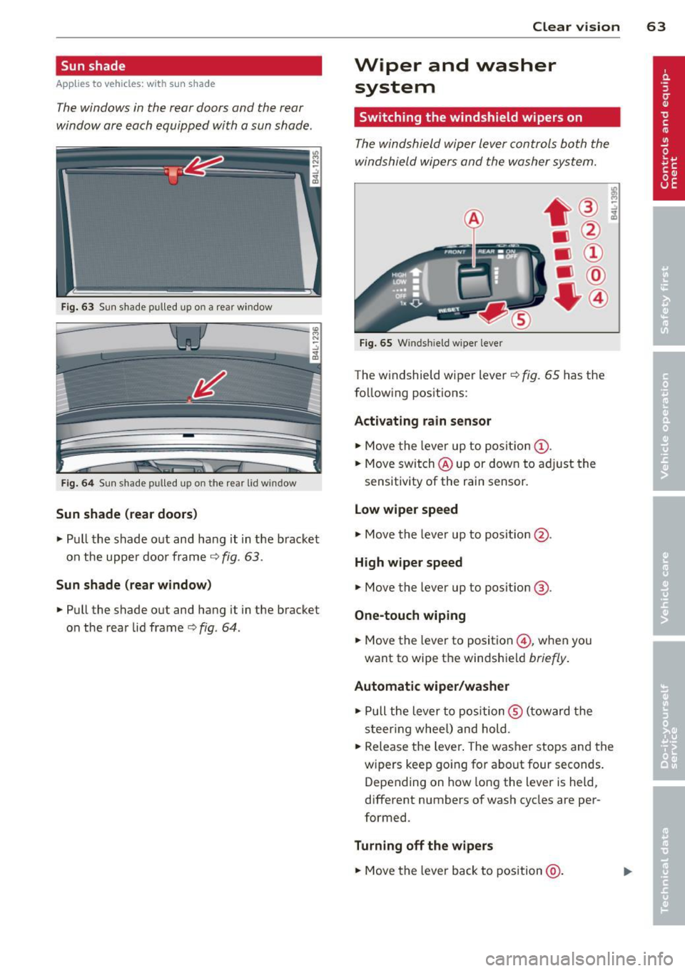
Fig. 63 Sun shade p ulled up on a rea r window
Fig . 6 4 Sun shade p ulled up on th e rear lid w in d ow
Sun shade (rear doors )
~ Pull the shade out and hang it in the b racket
on the upper door frame
r=;-, fig. 63 .
Sun sh ade (rear window )
~ Pull the shade out and hang i t in the bracket
on the rear lid frame
c> fig . 64 .
Clear vision 63
Wiper and washer
system
Switching the windshield wipers on
The windshield wiper lever controls both the
windshield wipers and the washer system.
F ig . 65 W inds hield w ipe r leve r
The windshield wiper l ever r=;-, fig. 65 has the
follow ing positions:
Acti vating rain sensor
~ Move the lever up to posit ion (!) .
~ Move switch @up or dow n to ad just the
sensitivity of the rain sensor.
L o w wiper speed
~ Move the lever up to posit ion @.
High w ipe r speed
~ Move the lever up to posit ion @.
One-touch wiping
~ Move the lever to position @ , when you
want to wipe the windshield
briefly .
Automat ic wiper /wa sher
~ Pull the lever to position ® (toward the
s t eer ing whee l) and hold.
~ Release the Lever . The washer stops and the
w ipers keep go ing for about four seconds.
Depending on how long the Lever is held ,
different numbers of wash cycles are per
formed .
Turning off the w ipe rs
~ Move the lever back to position @ .
Page 84 of 340
82 Seats and st o rage
Retractable luggage compartment cover
The luggage compartment cover keeps lug
gage or other objects out of view .
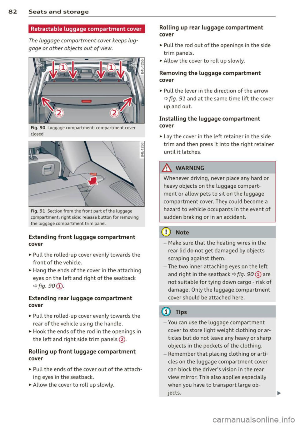
Fig. 90 Luggage compartment: compartment cover
closed
Fig . 91 Section from the front part of t he luggage
compartment, right side: release button for removing
the lu ggage compartme nt trim panel
Exte nding f ront luggag e co mpa rtment
c o v er
.. Pull the rolled-up cover evenly towards the
front of the vehicle.
.. Hang the ends of the cover in the attaching
eyes on the left and right of the seatback
q fig. 90@.
Extendi ng re ar luggage compartment
cove r
.. Pull the rolled-up cover evenly towards the
rear of the vehicle using the hand le.
.. Hook the ends of the rod in the openings in
t h e left and right s ide tr im pane ls @ .
Rolling up f ront luggage compa rtment
co ver
.. Pull the ends of the cover o ut of the atta ch
i ng eyes in the seatback.
.. Allow the cover to roll up slowly.
Rolling up r ear luggag e compartm ent
co ve r
.. Pull the rod out of the openings in the side
trim panels .
.. Allow the cover to roll up slowly.
Remov ing the lug gag e compartment
co ve r
.. Pull the lever in the direction of the arrow
q fig. 91 and at the same time lift the cover
up and out.
In stalling the luggag e comp artm ent
co ver
.. Lay the cover in the left retainer in the side
trim and then press it into the right retainer
until it latches .
A WARNING
Whenever driving, never place any hard or
heavy objects on the luggage compart
ment or a llow pets to s it on the luggage
compartmen t cover. They could become a
hazard to vehicle occupants in the event of
sudden braking or in an accident .
(D Note
-Make s ure that the heat ing wires in the
rea r lid do not get damaged by objects
sc raping aga inst them .
- T he two inne r attachi ng eyes on the left
and r ight in the seatback
q fig . 90 @ are
not suitable for tying down cargo -risk of
damage. Only the luggage compartment
cover should be attached here.
(D Tips
- You can use the luggage compartment
cover to store light weight clothing or ar
ticles but do not leave any heavy or sharp
objects in the pockets of the clothing.
- Remember that plac ing clothing or arti
cles on the luggage compartment cover
can block t he driver's vision in the rear
view m irror . This also applies especially
when you have to transport large ob
jec ts.
Page 86 of 340
84 Seats and storage
Loading
.. Fold the center seatback fo rward ¢ page 80 .
.. Remove the sack from the luggage compart-
ment and unfold it .
.. Place the empty sack over the lowered seat
back so that the end with the zip fastener is
in the luggage compartment.
.. Load objects from the luggage compart
ment into the sk i sack ¢
&-
Securing
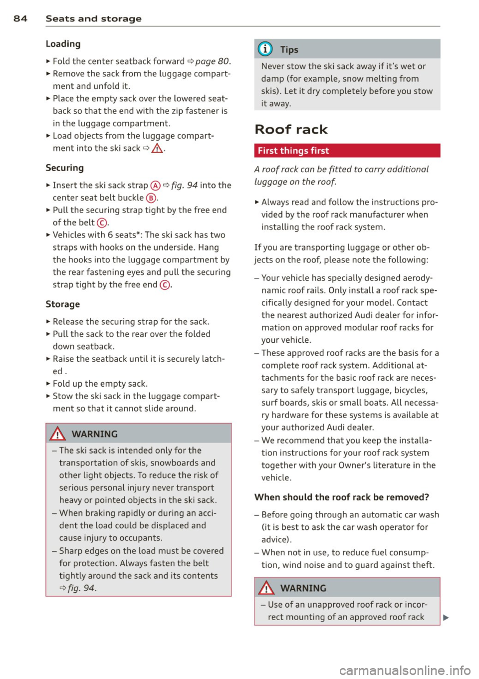
.. Insert the ski sack strap@¢ fig. 94 into the
center seat be lt buck le
@ .
.. Pull the securing strap tight by the free end
of the belt ©-
.. Vehicles with 6 seats*: The ski sack has two
straps with hooks on the underside . Hang
the hooks into the luggage compartment by
the rear fastening eyes and pull the secur ing
strap tight by the free end ©-
Storage
.. Release the securing strap for the sack .
.. Pull the sack to the rear over the folded
down seatback.
.. Raise the seatback unt il it is securely latch
ed .
.. Fold up the empty sack .
.. Stow the ski sack in the luggage compart
ment so that it cannot slide around.
A WARNING
-
-The ski sack is intended only for the
transportation of skis, snowboards and
other light objects. To reduce the risk of
serious persona l injury never transport
heavy or pointed objects in the ski sack.
- When brak ing rapidly or during an acci
dent the load could be displaced and
cause injury to occupants.
- Sharp edges on the load must be covered
for protect ion. Always fasten the belt
tightly around the sack and its contents
¢fig. 94.
(D Tips
Never stow the ski sack away if it's wet or
damp (for examp le, snow me lting from
skis). Let it dry complete ly before you stow
i t away.
Roof rack
First things first
A roof rack can be fitted to carry additional
luggage on the roof.
.. Always read and follow the instructions pro
vided by the roof rack manufacturer when
installing the roof rack system .
If you are transporting luggage or other ob
jects on the roof, please note the following :
- Your vehicle has spec ially designed aerody-
namic roof rails. Only install a roof rack spe
cifically designed for your model. Contact
the nearest authorized Aud i dealer for infor
mat ion on approved modula r roof racks for
your veh icle.
- These approved roof racks are the basis for a
complete roof rack system. Additional at
tachments for the basic roof rack are neces
sary to safely transport luggage, bicycles,
surf boards, skis or small boats. All necessa
ry hardware for these systems is available at
your authorized Audi dealer.
- We recommend that you keep the installa
tion instructions for your roof rack system
together with your Owner's literature in the
veh icle.
When should the roof rack be removed?
-Before going through an automatic car wash
(it is best to ask the car wash operator for
advice).
- When not in use, to reduce fuel consump
tion, wind noise and to guard against theft.
A WARNING
-
- Use of an unapproved roof rack or incor-
rect mounting of an approved roof rack
Page 108 of 340
106 On the road
Starting and stopping
the engine
Starting the engine
The engine can only be started with your orig
inal Audi key.
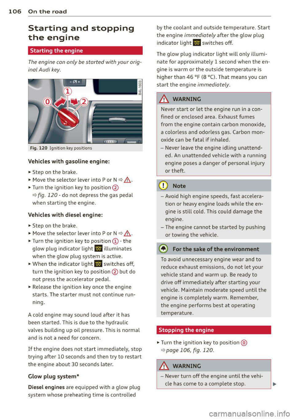
Fig. 120 I gni tion key positio ns
Vehicles with gasoline engine:
.. Step on the brake .
.. Move the selector lever into P or N
~ ,&. .
.. Tu rn the ignition key to position @
~ fig. 120 -do not depress the gas pedal
when starting the engine.
Vehicles with diesel engine:
.. Step on the brake .
.. Move the selector lever into P or N
~ ,&..
.. Turn the ign ition key to position ©- the
glow plug indicator light
m illuminates
when the glow plug system is act ive .
.,. When the indicator l ight
I.I sw itches off,
turn the ignition key to pos it ion @ but do
not press the accelerator pedal.
.,. Re lease the ignition key once the engine
sta rts. The starter must not continue run
ning.
A cold engine may sound loud after it has
been started . This is due to the hydraulic
va lves building up oil pressure. This is normal
and is not a need for concern.
If the engine does not start immediately, stop
trying after 10 seconds and then try to restart
the engine about 30 seconds Later.
Glow plug system*
Diesel engines are equipped with a glow plug
system whose preheating t ime is controlled by the coo
lant and outs ide temperature . Start
the engine
immediately after the glow plug
indicator light
m sw itches off.
The glow plug indicator light will only illumi
nate for approximate ly 1 second when the en
gine is warm or the outside temperature is
higher than 46 °F (8 °C). That means you can
start the engine
immediately .
A WARNING
-Never start or let the engine run in a con-
fined or enclosed area. Exhaust fumes
from the engine contain carbon monoxide,
a colorless and odorless gas . Carbon mon
oxide can be fatal if inhaled.
- Never leave the engine idling unattend
ed. An unattended veh icle w ith a runn ing
engine poses a danger of personal injury
or theft .
(D Note
- Avo id high engine speeds, fast accelera
tion or heavy engine loads while the en gine is still cold. This could damage the
eng ine .
- Th e engine cannot be started by pushing
or towing the vehicle .
@ For the sake of the environment
To avoid unnecessary engine wear and to
reduce exhaust emissions, do not let your
vehicle stand and warm up. Be ready to
drive
off immediately after starting your
vehicle. Maintain moderate speed until the
engine is completely warm . Remember,
the engine performs best at operating
temperature.
· Stopping the engine
.,. Turn the ignition key to posit ion @
~page 106, fig . 120 .
A WARNING
-
-Never turn off the engine until the vehi-
cle has come to a complete stop.
Page 110 of 340

108 On the road
reached operating temperat ure -other
wise yo u risk engine damage.
- The eng ine cannot be sta rted by pushing
or towing the vehicle.
@ For the sake of the environment
Do not allow the engine to warm up with
t he vehicle stationary. Start driving righ t
away . In th is way you avoid unnecessa ry
emissio ns.
@ Tips
If you open the drive r's door when the ig
nition is switched o n, a buzze r sounds and
the message
Ignition is on appears i n the
instrument cluster disp lay. Please switch
the ignition off.
Switching engine off with the~
button
App lies to veh icles: wit h Co nvenience key
Fig . 122 Conve nie nce key : ENG INE S TOP butto n
.. Bring your vehicle to a complete stop.
.. Move the selector lever to the P or N pos i-
t ion.
.. Press the
!STOP ! button c;, fig. 122 .
Pressing the ! STOP ! button once switches off
the eng ine and the ignition. If you press t he
!STOPI button again for more than 1 second,
the steering is locked , provided that the selec
tor lever is in t he P pos it ion
c;, & .
Emergency OFF function
If necessary, the eng ine can be sw itched off
wi th the selector lever in the R, Dor S posi
tions . To do so, step on the brake peda l and press and ho
ld the
! S T OP ! button (vehicle
s p eed must be less than 6 mph/ 10 km/ h).
.&_ WARNING
-
- Never turn off the engine until the vehi-
cle has come to a complete stop.
- The brake booster and servotronic only
work when the engine is running. With
the ignition turned off, you have to apply mo re force when steeri ng or brak ing .
Since you cannot stee r and stop normal
ly, t his can lead to acc idents and se rious
. . . in Ju ries.
- For safety reasons, you sho uld a lways
pa rk your vehi cle wit h the selector lever
i n P. O therwise, the vehicle could inad
ver ten tly roll aw ay.
- Afte r the eng ine has been switch ed off,
t he r adi at or f an can co ntinu e to run f or
up to 10 minu tes -even with the igni tion
switched off . It can also switch on again
after some t ime if the coolant tem pera
ture rises as the resu lt of a heat b uildup
or if the engine is hot and the engine
compa rtment is additionally heated by
the sun's rays.
(D Note
If the engine has been under heavy load
for an extended pe rio d, heat b uilds up in
the engine compartment after the engi ne
i s sw itched off -there is a r isk of damag ing
the e ng in e. A llow th e engi ne to run a t id le
fo r abo ut 2 minutes befor e switching it
off .
Driver messages in the instrument
cluster display
Applies to veh icles: w it h Co nvenience key
If a func tion is not present, a driver message
appears .
No key identified
This message appears when t he I STAR T I but-
ton is pr essed if there is no master key ins id e
the vehi cle or if t he system does not recogn ize
IJ,-
Page 114 of 340
112 On the road
• To increase/decrease the speed quickly, hold
the lever in the
0 10 direction unti l the de
s ired speed is displayed.
You can a lso press the accelerator pedal down
to increase your speed , e .g. if you want to
pass someone . The speed yo u saved earlier
will resume as soon as you release the acceler
ator pedal.
If , however, you exceed your saved speed by
5 mph (10 km/h) for longer than 5 minutes ,
the cruise contro l will turn off temporarily .
The symbol will go out but the saved speed
will be retained.
Presetting your speed
You con preset your desired speed while the
vehicle is not moving.
• Turn on the ignition.
• Pull lever into position
(D c:> page 111 ,
fig. 124.
• Press the lever in the 0 or O direction to
increase or decrease you r speed .
• Release the lever to save that speed .
This funct ion makes it possible, for example,
to save the speed you want before driving on
the highway . Once o n the hig hway, activate
the cruise contro l by pulling the lever toward
(D .
Switching the system off
Temporary deactivation
• Press the b ra ke peda l, or
• Press the lever into pos it ion @ (not clicked
into p lace)
r:!;> page 111, fig . 124, or
• Drive for longer than 5 minutes at more
than 5 mph (10 km/h) above the stored
speed.
Switching off completely
• Press lever in to posi tion @ (clic ked into
place), or
• Switch the ignition off .
The system reta ins the saved speed if yo u de
activate the cru ise con trol tempo rari ly. To re- sume the saved speed, re
lease the brake ped
al and pu ll the lever to position
(D .
Switch ing the igni tion off e rases the saved
speed.
A WARNING ~
You shou ld only ret urn to the saved speed
if it is not too fast for the c urrent traffic
conditions -risk of an accident!
-
Page 115 of 340
Adaptive cruise control Speed and distance
control system
Description
Applies to vehicles: with adaptive cruise cont rol
The adaptive cruise control driver assistance
program is a combined speed and distance
control system .
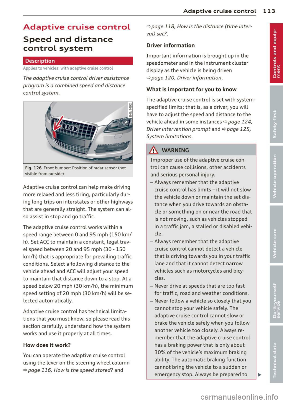
Fig . 126 Front bu mper: Pos itio n of r adar sen sor (not
vi sibl e from out side)
Adapt ive cruise control can he lp ma ke driv ing
more relaxed and less tiring , particularly dur
i n g long trips on interstates or other hig hways
that are genera lly st raight. The system can al
so ass ist in stop and go traffic .
The adaptive cruise co ntrol works within a
speed range be tween 0 and 95 mph (150 km/
h). Set ACC to maintain a constant , legal trav
el speed between 20 and 95 mph (30 -150
km/h) that is appropriate for prevailing traffic
conditions. Select a following distance to the
veh icle ahead and ACC will adjust your speed
to maintain that d istance down to a stop . At a
speed below 20 mph (30 km/h), the min imum
speed setting of 20 mph (30 km/h) will be se l ected automati ca lly.
Adaptive cruise control has technical limita
tions that you must know, so p lease read th is
section carefully , understand how the system
wo rks and use it properly at a ll times.
How does it work?
You can operate the adaptive cruise control
using the lever on the steering wheel column
c::> page 116, How is the speed stored? and
Ad apti ve crui se control 11 3
c::> page 118, How is the distance (time inter
val) set? .
Driver information
Important information is brought up in the
speedomete r and in the instr ument clus ter
display as the vehicle is being driven
c::> page 120, Driver informat ion .
What is important for you to know
The adaptive cru ise contro l is set w ith system
spe cified lim its; that is, as a driver, you will
have to adjus t the speed and distance to the
vehicle ahead in some instances
c:> page 124,
Driver intervention prompt
and c::> page 125,
System limitations.
A WARNING
Imp roper use of the adaptive cruise con
trol can cause collisions, other accidents
and serious personal injury.
- Always remember that the adaptive cru ise contro l has limits -it will not slow
the vehicle down or ma inta in the set d is
tance when you dr ive towards an obsta
cle or someth ing o n or nea r the road that
is not movi ng, such as ve hicles stopped
in a tra ffic jam, a sta lled or d is ab led vehi
cle.
- Always remembe r that the adaptive
cru ise con tro l canno t detect a vehi cle
that is driving towards yo u in your traffic
lane and that it cannot detect narrow
vehicles s uch as motorcycles and bicy
cles.
- Never drive at speeds that are too fast
for traffic, road and weather conditions.
- Never follow a vehicle so closely that yo u
cannot stop your vehicle safely. The
adaptive cruise control cannot s low or
brake the vehicle safely when you follow
another vehicle too close ly. Always re
membe r that the adaptive cruise control
has a braking powe r th at is o nly about
30% of the veh icle 's maxim um braking
ab ility. The a uto mat ic bra kin g f unction
canno t bring the veh icle to a s udden or
emergency stop . Always be p repared to
-
Page 124 of 340
122 Adaptive cruise control
select information from the trip computer,
navigation system* or adaptive cruise control.
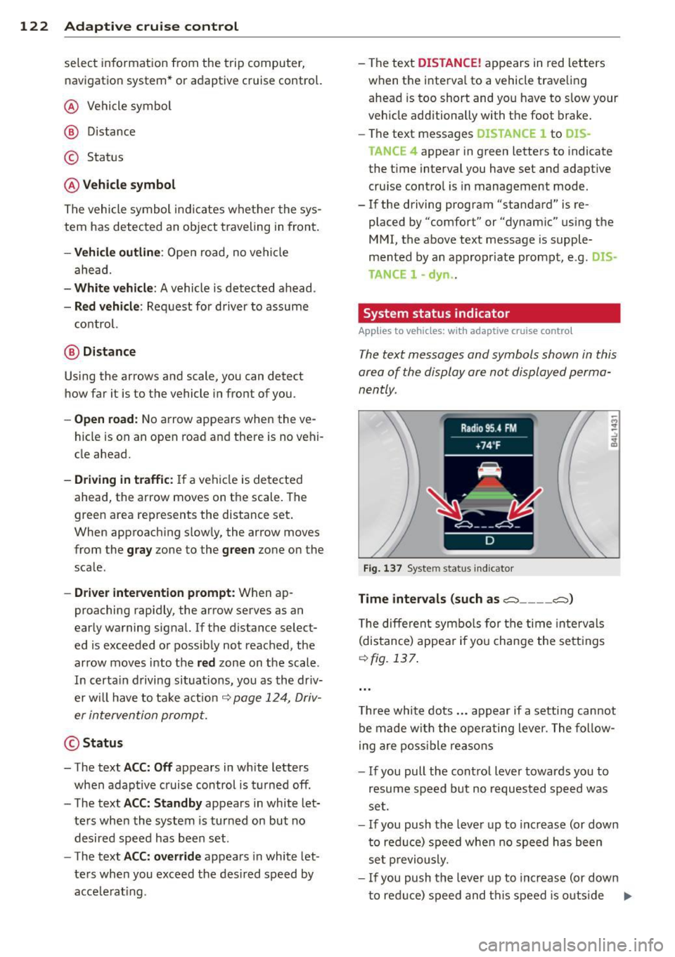
@ Vehicle symbol
@ Distance
© Status
@Vehicle symbol
The vehicle symbol indicates whether the sys
tem has detected an object traveling in front .
-Vehicle outline: Open road, no vehicle
ahead.
- White vehicle: A vehicle is detected ahead.
-Red vehicle : Request for driver to assume
control.
@ Distance
Using the arrows and scale, you can detect
how far it is to the vehicle in front of you.
- Open road: No arrow appears when the ve
hicle is on an open road and there is no vehi
cle ahead.
- Driving in traffic: If a vehicle is detected
ahead, the arrow moves on the scale. The
green area represents the distance set.
When approach ing slow ly, the arrow moves
from the
gray zone to the green zone on the
scale .
-Driver intervention prompt : When ap
proaching rap idly, the arrow serves as an
early warning signal. If the d istance select
ed is exceeded or possibly not reached, the
arrow moves into the
red zone on the scale.
In certa in driving situations, you as the driv
er w ill have to take action
c::> page 124, Driv
er intervention prompt.
@Status
- The text ACC: Off appears in white letters
when adaptive cruise control is turned off.
- The text
ACC: Standby appears in white let
ters when the system is turned on but no
desired speed has been set.
- The text
ACC: override appears in white let
te rs when you exceed the desired speed by
acce lerat ing. - The text
DI
STANCE! appears in red letters
when the interva l to a vehicle traveling
ahead is too short and you have to slow your
veh icle additionally with the foot brake.
- The text messages
DISTANCE 1 to DIS
TANCE
4 appear in green letters to indicate
the t ime interval you have set and adapt ive
cruise control is in management mode.
- If the driving program "standard" is re
placed by "comfort" or "dynam ic" using the
MMI , the above text message is supple
mented by an appropriate prompt, e.g.
DIS
TANCE
1 -dyn .
System status indicator
Applies to vehicles : wi th adap tive c ruise contro l
The text messages and symbols shown in this
area of the display are not displayed perma
nently.
Fig. 137 System status indicator
Time intervals (such as.::::::, ____ .::::::,)
The different symbols for the time intervals
(distance) appear if you change the settings
c::>fig. 137.
Three white dots ... appear if a setting cannot
be made w ith the operating lever. The follow
ing are possible reasons
- If you pull the cont ro l lever towards you to
resume speed but no requested speed was
set.
- If you push the lever up to increase (or down
to reduce) speed when no speed has been
set previously.
- If you push the lever up to increase (or down
to red uce) speed and this speed is outs ide
Ill>
Page 132 of 340

130 Audi side assist
-The radar sensor's vision can be reduced
or entirely blocked by rain, snow, and
heavy spray . This can result in side assist
not adequately detecting vehicles or, in
some cases, not detecting them at all.
Always keep an eye on the direction you
are traveling and the relevant area
around the vehicle.
- Please note that side assist indicates
there are approaching vehicles, or
vehicles in your blind spot, only after
your vehicle has reached a driving speed
of at least 19 mph (30 km/h).
- Side assist signal does not work around
tight corners (turning radius less than
328 feet, or 100 m).
- Side assist is no replacement for the driv
er's full attention. The driver alone is re
sponsible for lane changes and similar
driving maneuvers. Always keep an eye
on the direction you are traveling and the relevant area around the vehicle.
- To ensure that you do not adversely af
fect side assist, do not block the area on
the rear bumper where the radar sensors
are located with foreign objects (such as
stickers or bicycle racks).
- Make sure that the signal light on the
outside mirror is not blocked by stickers
or other items.
(Di Tips
- Side assist automatically deactivates if it
detects that the radar sensors are
blocked ¢
page 135. The indicator light
on the button goes out .
- The area on the bumper where the radar
sensors are located must consistently re
main free of snow, ice, and heavy soiling
so that side assist can function properly.
Follow the additional notes on
¢page 136.
-For vehicles with a factory installed tow
ing hitch* or a trailer hitch* that was in
stalled later according to factory specifi
cations, side assist is automatically deac- tivated
as soon as the electrical connec
tion to the trailer electrical socket is made
¢ page 135.
-For vehicles with a trailer hitch that was
not installed according to factory specifi
cations, switch off the side assist when
towing a trailer .
- Additional tinting on the front side win
dows can make it harder to see and cor
rectly understand the signal light on the
outside mirror.
- For Declaration of Compliance to United
States FCC and Industry Canada regula
tions¢
page 319.
Sensor detection area
Applies to vehicles: with side assist
-----··· .... ·--·--
@ / ,
--
ill b''T -
Fig. 150 Sc hematic illustration: Sensor detectio n area
The detection ¢ fig. 150 of the radar sensor
detection area is made up of:
-
- the approach area (light red area) (D, about
230 feet (70 m) behind the vehicle, and
- the "blind spot" (dark red area) @.
The radar sensors cover the adjacent left and
right lanes. Other lanes are
not covered by the
radar sensors.
(D Tips
Side assist does not measure actual lane
width. The system assumes a fixed lane
width . Detection in the left and right lanes
is based on this assumed lane width.
When driving on narrow roads or when
driving to the left or right of the center of
a travel lane, it is possible that vehicles
will be detected that are
not in the lane
Page 137 of 340

Lane width
Applies to vehicles: with side assist
-· Fig. 155 Lan es o f a norma l wid th a re in detect ion area
Fig . 156 Narrow lanes: Side ass ist may detect vehicles
two la nes away
Side assist's detection area is designed to cov
e r l anes of standard w idth to the left and
r ight of your travel lane, depending on wheth
er you dr ive in the center of your lane or closer
to the edge.
I f you drive in narrow lanes, s ide ass ist's de
tec tion a rea may a lso incl ude other lanes -es
pec ia lly if you tend to drive on the edge of
your lane
c:::> fig. 156 . Under these cond it ions,
ve hicles can also be detected that are two
lanes away, and side assist then could switch
between the informat ional and warn ing stage
signals.
When driving in very wide lanes, vehicles in
the adjacent lane may not be detected be
cause they are not inside the detection area.
Notes
Messages in instrument cluster display
Applies to vehicles: with side assist
If s ide ass ist t urns off automa tically, the ind i
cator l igh t on the button wi ll go ou t and you
Aud i side assist 135
will see a message in the instrument cluster
display:
Audi side assist not available: sensors
bloc ked
The side assist sensors are built into the rear
bumper on the left and r ight (not visible on
the outside)
c:::> page 129, fig . 147. To ensure
that you do not adversely affect the way side
ass ist functions, foreign objects (such as stick
ers or bicycle racks) should not be attached to
the area on the rear bumper where the sen
sors a re located . If side ass ist functions are
adverse ly affec ted, you w ill see th is message
in the instrument cluster disp lay . Remove any
th ing t hat may be blocking the sensors.
If no vehicle is detected for a longer per iod of
t ime wh ile dr iv ing, s ide ass ist w ill also switch
off automatically.
Audi s ide as sist cu rrentl y not available
If there is a temporary problem (such as the
vehicle 's battery charge be ing low), side assist
cannot be act ivated temporar ily .
Audi side assis t: sy stem fault
Have the system checked by an author ized
Audi dealer or qualified workshop.
Audi side assist not availabl e when
towing
The radar sensor's view is limited when tow
ing a tra iler. For vehicles with a factory instal
led tow ing hitch or a trailer hitch that was in
stalled later according to facto ry specifica
tions, s ide ass ist is automatically deact ivated
as soon as the ele ctrical connection to the
trailer's e lectrical socke t is made, and this sta
tus message appears in the instrument clus
ter display. Deactivation cannot be guaran
teed when using a retrofitted towing hitch
that was
not installed according to factory
specifications.