AUDI Q7 2014 Owner´s Manual
Manufacturer: AUDI, Model Year: 2014, Model line: Q7, Model: AUDI Q7 2014Pages: 340, PDF Size: 85.02 MB
Page 301 of 340

Loosening
• Install the wheel bolt wrench over the
whee l bolt and push it down as far as it wi ll
go.
• Take tight hold of th e
end of the wrench
handle and turn the whee l bolts
counter
clockwise
abou t one single turn in the di rec·
tion of arrow
c::> fig. 262 .
Tightening
• Install the wheel bolt wrench over the
wheel bolt and push it down as far as it will
go .
• Take tight hold of the
end of the wrench
handle and turn each wheel bolt
clockwise
until it is seated .
& WARNING
-Do not use force or hurry when changi ng
a whee l· you can cause the vehicle to slip
off the jac k and cause serious personal
injuries .
-Do not loosen the wheel bolts more than
one turn
before you raise the veh icle with
the jack. -You risk an injury.
(j) Tips
If a wheel bolt is very tight, you may find it
easie r to loosen by carefully pushing down
on the end of the wheel bolt wrench with
one foot only. As you do so, hold on to the
car to keep yo ur balance and take care not
to slip.
Raising the vehicle
The vehicle must be lifted with th e jack first
before the wheel can be removed .
Fig. 263 Sill pane ls: m arkin gs
What do I do now? 299
Fig. 264 Sill: p ositioning the jack
• Activate the vehicle jack mode* (only
veh icles with Adaptive Air Suspension)
c::> page 159 .
• Engage the parking brake to prevent your
vehicle from rolling unintentionally
• Move the
selector lever to position P .
• Find the marking (imprint) on the sill that is
nea rest the whee l that will be changed
c::>fig. 263. Behind the marking, there is a
lifting point on the sill for the jack.
• Turn the
jack located under the lifting point
on the sill to raise the jack until its arm@
c::> fig. 264 is located under the designated
plastic mount
c::> .&. c::> Q) .
• Align the jack so that its arm@ c::> fig. 264
engages in the designated lifting point in
the door s ill and the movable base® lies
flat on the ground. The base@ must be
ver
tical
under the lifting point@.
• Wind the jack up further until the flat tire
comes off the ground
c::> .,& .
Position the jack only under the designated
lifting points on the sill
c::> fig. 263. There is
exactly
one locat ion for each whe el. The jack
must not be positioned at any other location
c::> .&. c::> Q).
An unstable surface under the jack ca n cause
the vehicle to slip off the jack. Always provide
a firm base for the jack on the ground . If nec
essary place a sturdy board or similar support
under the jack . On
hard, slippery surfaces
(such as tiles) use a rubber mat or similar to
prevent the jack from slipping
c::> ,&.. .,,.
Page 302 of 340

300 What do I do now?
& WARNING
-You or your passengers could be injured
while changing a wheel if you do not
follow these safety precautions:
- Position the jack only at the designated
lifting points and align the jack. Other
wise, the jack could slip and cause an injury if it does not have sufficient hold
on the vehicle.
- A soft or unstable surface under the
jack may cause the vehicle to slip off the jack. Always provide a firm base for
the jack on the ground . If necessary,
use a sturdy board under the jack.
- On hard, slippery surface (such as tiles)
use a rubber mat or similar to prevent
the jack from slipping.
- To help prevent injury to yourself and
your passengers:
- Do not raise the vehicle until you are
sure the jack is securely engaged.
- Passengers must not remain in the ve
hicle when it is jacked up.
- Make sure that passengers wait in a
safe place away from the vehicle and
well away from the road and traffic.
- Make sure jack position is correct, ad
just as necessary and then continue to
raise the jack.
(D Note
Do not lift the vehicle by the sill. Position
the jack only at the designated lifting
points on the sill. Otherwise , your vehicle
will be damaged.
Taking the wheel off /installing the
inflatable spare tire
Follow these instructions step-by-step for
changing the wheel
Fig. 265 Changing a wheel: alignment pin inside the
top hole
After you have loosened all wheel bolts and raised the vehicle off the ground, remove and
replace the wheel as follows:
Removing the wheel
.,. Remove the topmost wheel bolt completely
and set it aside on a
clean surface.
.,. Screw the threaded end of the
alignment
pin
from the tool kit hand-tight into the
empty bolt hole
¢ fig . 265.
.,. Then remove the other wheel bolts as de
scribed above.
.,. Take off the wheel leaving the alignment pin
in the bolt hole ¢(D.
Putting on the inflatable spare tire
.,. Inflate the inflatable spare tire ¢ page 296
and push the wheel over the alignment pin.
"Screw in and tighten all wheel bolts
slightly.
.,. Remove the alignment pin and insert and
tighten the remaining wheel bolt slightly
like the rest .
.,. Turn the jack handle counter-clockwise to
lower the vehicle until the jack is fully re
leased .
" Use the wheel bolt wrench to tighten all
wheel bolts firmly ¢
page 298 . Tighten
them
crosswise, from one bolt to the (ap
proximately) opposite one, to keep the
wheel centered.
Page 303 of 340

(D Note
When removing or installing the wheel,
the rim could hit the bra ke rotor and dam
age the rotor . Wor k carefully and have a
second person help you.
- W hen mounting tires with
unidirectional
tread design
ma ke s ure the tread pat
tern is pointed the r ight way
<=> page 301.
-The wheel bolts should be clea n and easy
to tu rn . Check for d irt and corrosio n on
t h e mat ing su rfaces of both the whee l
and the hub. Remove a ll dirt from these
su rfaces before remo untin g t he wheel.
Tires with unidirectional tread design
Tires with unidirectional tread design must be
mounted with their tr ead pattern point ed in
the right dire ction.
Using a spare tire with a tread pattern
intended for use in a specific direction
W hen using a spa re tire w ith a t read patte rn
in te nded fo r use in a specific direction, p lease
n ot e t he followi ng:
- The direction of rotation is marked by an ar
row on the side of the tire .
- If the spare t ire has to be installed in the in
correct di rection, use the spa re tire only
tem porarily si nce th e tir e will not be able to
a ch ieve i ts op timum pe rfo rm ance chara cter
is tics with reg ard to aq uaplani ng, noise and
wea r.
- W e recommend that you p ay pa rticular at
tent io n t o this fact du ring wet weathe r and
t h at you adjus t your spee d to matc h roa d
con dit ions .
- Re place the fla t tire w ith a new one and
have it installed on your vehicle as soon as
poss ible to restore the hand ling advantages
of a unid irect iona l tire.
What do I do now?
Notes on wheel changing
P lease read t he i nfo rmat ion c:> page 284, New
t ires and replacing tires and wheels
if y ou a r e
go ing to use a sp are tire w hich is different
from the ti res on yo ur vehicle.
After yo u cha nge a tire:
- Check the tire pressure on the spare imme
diately after installation .
- Have the wheel bolt tightening torque
che cked with a torque wrench as soon as
possible by your authorized Audi dealer or
a qualified workshop.
- With steel and alloy wheel rims, the wheel
bolts are correctly tightened at a torque of 120 ft lb (160 Nm) .
- If you notice that the wheel bolts are cor
roded and difficult to turn while changing
a tire, they should be replaced before you
check the tightening torque.
- Repla ce the flat tire with a new one and
have it installed on your vehicle as s oon as
possible. Remount the wheel cover.
Until then, drive with extra care and at re
duced speeds .
&_ WARNING
-
- If yo u are goi ng to e quip yo u r ve hicl e
wit h tires o r rims whi ch di ffer from those
which were fac to ry installed, t hen be
sure to rea d the information
c:> page 284,
New tires and replacing tires and
wheels.
- Always make s ure the damaged wheel o r
even a flat tire and the jack and t ool kit
are prope rly secured in the luggage com
pa rtme nt and are not loose in the pas
senge r compartment .
- In an accident or sudden maneuver they
could fly forwa rd, inj uri ng a nyo ne in the
veh icle.
- Always sto re damaged wheel , jack a nd
too ls sec urely in the luggage compa rt
men t. Othe rwise, in a n accide nt o r sud
de n m aneuver they could fly forwa rd,
c a u sing i nju ry to passenger s in th e ve hi
cle.
301
•
•
Page 304 of 340
302 Fuses and bulbs
Fuses and bulbs
Electrical fuses
Replacing fuses
Fuses that have blown will have metal strips
that have burned through.
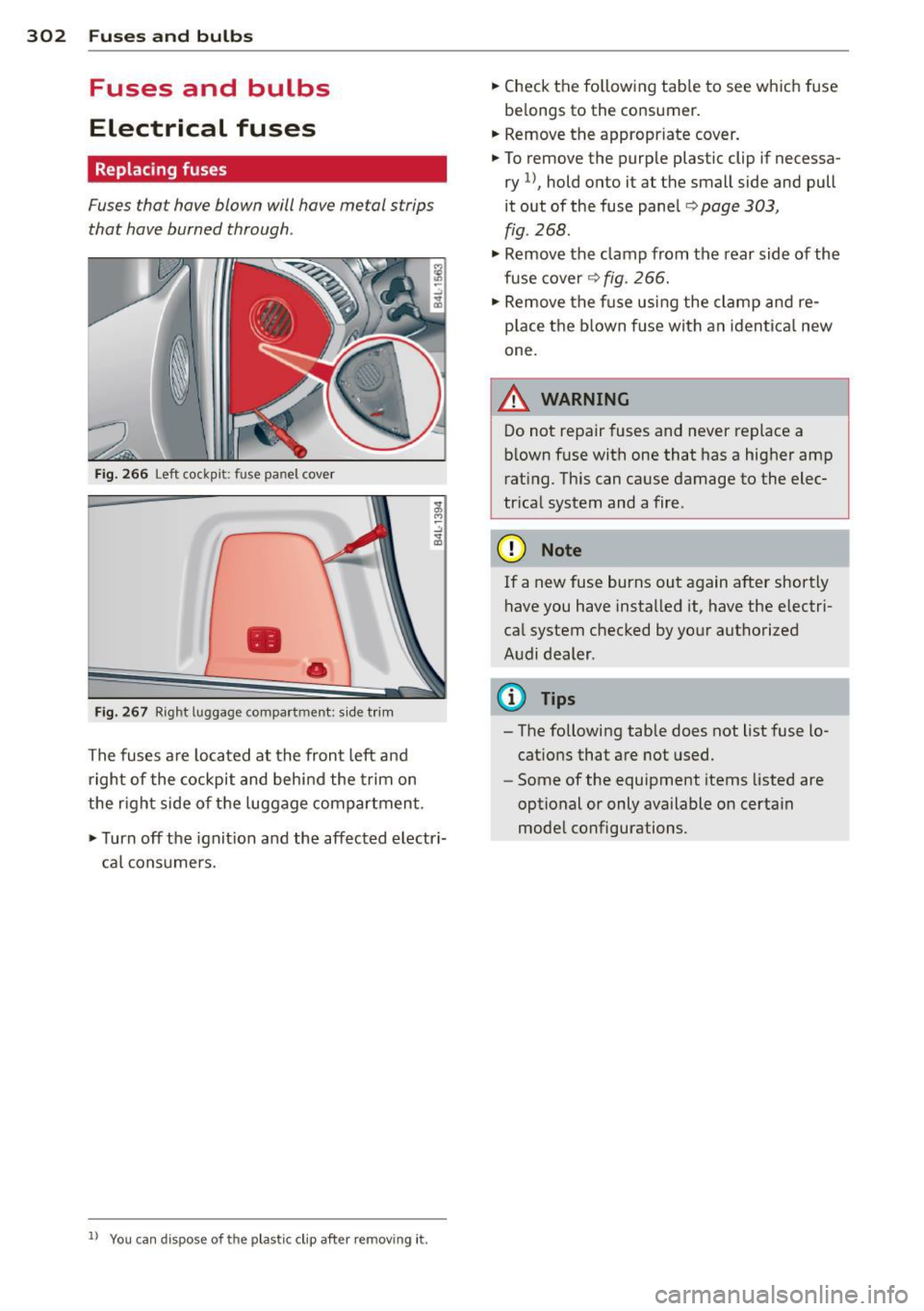
Fig . 266 Left cockp it: fuse panel cover
•
•
F ig . 267 Right luggage compa rtment: s ide t rim
The fuses are located at the fron t left and
right of the cockpit and behi nd the trim on
the r ight side of the luggage compartmen t.
.,. Turn off the ignit ion and the affected electri
cal consumers.
ll You ca n dispose of the plastic clip after remov ing it.
.. Check the following tab le to see wh ich fuse
be longs to the consumer.
.. Remove t he appropriate cover .
.. To remove the purp le plastic clip if necessa
ry
1) , hold onto it at the small side and pull
it out of the fuse pane l
c:> page 303,
fig.
268 .
• Remove the clamp from the rear side of the
fuse cover
c:> fig. 266.
• Remove the f use us ing the clamp and re
p lace t he bl own f use with an iden tica l new
one.
A WARNING
--
Do not repair fuses and never replace a
b lown fuse with one that has a hig her amp
rat ing. Th is can ca use damage to the elec
tr ica l system and a fire .
(D Note
If a new fuse burns out again after shortly
have you have installed it, have the e lectri
ca l system checked by yo ur authorized
Audi dealer .
{!) Tips
-The following table does not list fuse lo
cat ions that are not used.
- Some of the equipment items listed are
optional or only available on certa in
mode l configurations .
Page 305 of 340
Fuses and bulbs 303
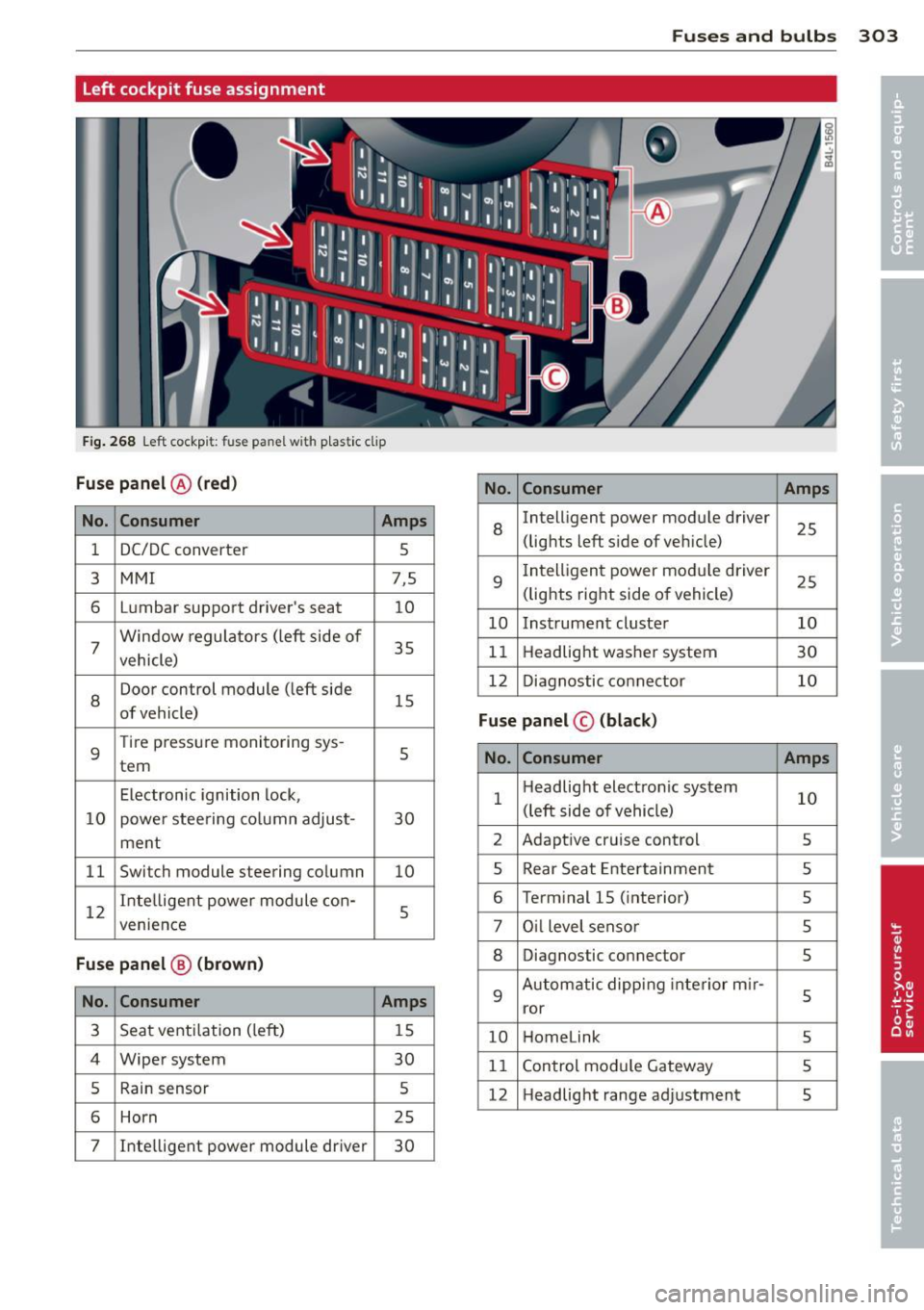
Left cockpit fuse assignment
F ig . 268 Left cockpit: fuse panel with p lastic clip
Fuse panel @ (red)
No. Consumer Amps
No. Consumer Amps
1 DC/DC converter
5
8
Intelligent power module driver
25
(lights left side of veh icle)
3
MMI 7,5
6 L umbar support driver's seat
10
7 Window
regulators (left side of
35
vehicle)
9
I ntelligent power module driver
25
(lights right side of vehicle)
10 Instrument cluster 10
11 Headlight washer system
30
8
Door control module (left side
15
of vehicle) 12
Diagnostic connector 10
Fuse panel © (black)
9
Tire pressure monitoring sys -
tern 5
No. Consumer
Amps
Electronic ignition lock,
10 power steering co lumn adjust- 30 1
Headlight
electronic system
10
(left side of vehicle)
ment 2
Adaptive cruise control
5
11 Switch module steering column
10 5 Rear
Seat Entertainment
5
12 Intelligent
power module con-
5
venience
6 Term inal 15 ( interior)
5
7 Oil level sensor
5
Fuse panel @ (brown) 8 Diagnostic connector
5
No.
Consumer Amps 9
Automatic dipping interior m ir-
5
ror
3 Seat ventilation (left)
15
10 Homelink
5
4 Wiper system
30
11 Control module Gateway 5
5 Rain sensor 5
12 Headlight
range adjustment
5
6 Horn 25
7 Inte
lligent power module driver
30
Page 306 of 340
304 Fuses and bulbs
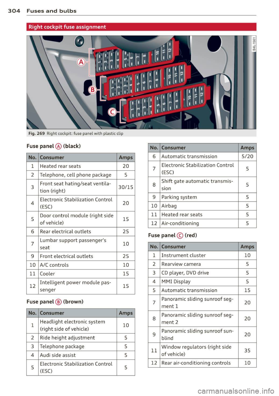
Right cockpit fuse assignment
Fig. 269 Right cockpit: fuse pane l w ith plastic clip
Fuse panel @ (black)
No. Consumer Amps
No. Consumer Amps 6
Automatic transmission
5/20
1 Heated rear seats
20
2 Telephone, cell phone package 5
7
Electronic Stabilization Control
5
(ESC)
3 Front seat
hating/seat ventila-
30/15
tion (right) 8
Shift gate automatic transmis-
s sion
4 Electronic
Stabil iz at ion Control
20
(ESC) 9 Parking system s
10 A
irbag 5
5 Door control module (right side
15
of vehicle) 11
Heat ed rear seats 5
12 A ir-conditioning
5
6 Rear electrical outlets 25
7
Lumbar support passenger's
10
seat
Fuse panel © (red)
No. Consumer Amps
9
Front electrica l outlets
25 1
Instrument cluster 10
10 A/C controls 10 2
Rearvi ew camera 5
11 Coo
ler
15 3 CD player, DVD drive
5
12 Inte
lligent powe r module pas-
15
4 MMI Display 5
senge r 5 Automatic t ransmission 15
Fuse panel@ (brown ) 7 Panoramic
sliding sunroof seg-
ment 1 20
No.
Consumer Amps
1 Headlight e
lectronic system
10
(right side of veh icle)
2 Ride height adjustment 5
8
Panoramic sliding sunroof seg-
20
ment 2
9 Panoramic
sliding sunroof sun-
20
blind
3 Telephone package 5
4 Audi side assist
5 11
W
indow regulators (right side
35
of vehicle)
s
Electronic Stabilization Control
(ESC) 5 12
Rear air-conditioning controls 10
Page 307 of 340
Fuse s and bulb s 305
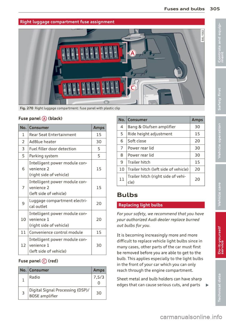
Right luggage compartment fuse assignment
0
Fig . 270 Right luggage compartment: fuse panel with plastic clip
Fuse pan el@ (black )
No. Con sumer Amps
1 Rear Seat
Entertainment
15
2 AdBlue heater 30
3 Fuel filler door detection 5
5 Parking system 5
Inte lligent power module con-
6 venience 2
15
(right side of vehicle)
Inte lligent power module con-
7 venience 2 15
(left side of vehicle)
9
Luggage compar tment electri-
20
cal outlet
Intelligent power module con-
10 venience
1
20
(right side of veh icle)
11 Convenience contro
l modu le
15
Intelligent power module con-
12 venience 1 30
(left s ide of ve hicle)
Fus e pa nel © (red )
No. Con
sumer
Amps
1 Radio
7,5/3
0
3 Digital
Signal Processing (DSP)/
30
BOSE amplifier
No. Consumer Amps
4 Bang & Olufsen amplifier
30
5 Ride height adjustment 15
6 Soft close 20
7 Power rear lid 30
8 Power rear lid
30
9 Trailer hitch 15
10 Trailer
hitch (left side of vehicle) 20
11 Trailer hitch (right
side of vehi-
20
cle)
Bulbs
Replacing light bulbs
For your safety, we recommend that you have
your authorized Audi dealer replace burned
out bulbs for you.
It is becoming increasingly more and more
difficult to replace vehicle light bulbs since in
many cases, other parts of the car must first
be removed before you are able to get to the
bulb. This applies espe cially to the light bulbs
in the front of your car which you can only
reach through the engine compartment.
Sheet metal and bu lb holders can have sharp
edges that can cause se rio us cu ts, and par ts
IJ>
Page 308 of 340
306 Fuses and bulbs
must be co rrectly taken apart and then prop
erly put back together to help prevent break
age of parts and long term damage from wa
te r that can enter housings that have not been
properly resealed.
F or your safety, we recommend that you have
your author ized Audi deale r replace any bulbs
for you, since your dealer has the proper tools,
the correct bulbs and the expertise.
Gas discharge lamps (Xenon lights)*:
Due to the high electrical vo ltage, have the
bu lbs rep laced by a qualified technician.
Headlights with Xenon light can be identified
by the high voltage sticker.
A WARNING
Contact with high-voltage components of
the electrical system and improper re placement of gas discharge (Xenon) head
light bulbs can cause serious personal in
jury and death .
- Xenon bulbs are pressurized and can ex
plode when be ing changed .
-Chang ing Xenon lamps requires the spe
cial train ing, instructions and equip
ment .
- Only an authorized Audi dealer or other
qualified workshop should change the
bulbs in gas d ischarge lamps.
A WARNING
There are parts with sharp edges on the
openings and on the bulb holders that can
cause serious cuts.
- If you are uncertain about what to do,
have the work performed by an author
ized Audi dea le r or other qualified work
shop. Serious personal injury may result
from improperly performed work .
(j) Tips
-If you must replace the light bu lbs your
se lf, always remembe r that the engine
compartment of any vehicle is a hazard
ous area to work in . Always read and
heed all WARNINGS
c::> page 257 ¢ _& .
-
- It is best to ask your authorized Audi
dealer whenever you need to change a
bulb .
Page 309 of 340

Emergency situations
General
This chapter is intended for trained emer
gency crews and working personnel who have the necessary tools and equipment to
perform these operations.
Starting by pushing or
towing
(D Note
Your v ehicl e is e quipped w ith an automatic
tra nsm iss io n. Cons eque ntly, the e ngine
cann ot be started by pus hing o r tow ing.
Starting with jumper
cables
If necessary, the engine can be started by
connecting it to the battery of another vehi
cle.
If th e engine shou ld fail to start because of a
d ischarged o r weak battery, the battery can be
connected to the battery of
another veh icle,
usi ng a
pair of jumper cables to start the en
gine .
Jumper c ables
Use only jumper cab les of sufficiently large
cross section to carry the starter cur rent safe
l y. Refer to the man ufacturer's specifications.
Use only jumper cables with
insulated te rm i
na l clamps w hich are d istinctly mar ked:
plus(+ ) cable in mos t ca ses co lore d red
minus(-) cable
i n most cases colored black .
A WARNING
Batteries con tai n elec trici ty, a cid, and gas.
Any o f these c an caus e ve ry ser ious or f atal
injury . Follow the instruc tions below fo r
safe han dling of your veh icle's battery .
- Alw ays s hield y our eyes and a void le an
ing over the batte ry w henever possib le .
Emergency situations 307
- A discharged battery can freeze at tem
pe rat ures just below 32 °F (0 °C). Before
connecting a jumpe r cable, you must
thaw the frozen battery c omp lete ly, ot h
e rwise it could explode.
- Do not allow battery acid to co ntact eyes
or skin . Fl ush any con tacted area wi th
wat er immediately .
- Imp roper use of a booster battery to
s tart a vehicle may cause an ex plosion.
- Vehicle batter ies generate expl osive gas
es. Keep sparks, flame and lighted c iga
rettes away from ba tte ries.
- Do not t ry to jump start a ny ve hicle w it h
a low ac id leve l in the battery.
- The voltage of the booste r battery m ust
also have a 12-Vo lt rat ing. T he capac ity
(Ah) of the booste r batt ery sho uld not b e
lowe r than that of th e discharged bat
t ery. Use o f batt eries of d iffe ren t vol tage
or su bstan tia lly differen t "Ah" rat ing
may cause an exp losion and pers onal in
jury .
- N ever ch arge a fr ozen batt ery. Gas t ra p
pe d in the ice may c ause an ex plosion .
- N ev e r ch arge o r use a batt ery th at h as
been fro zen . Th e batte ry case may have
be weake ned.
- U se o f batter ies of di ffere nt vol tage or
substantially differen t ca pa city (Ah) rat
i ng may cause an exp losion and injury .
T he ca pa c ity (Ah) of the booster battery
should not be lower than that of the dis
charged battery.
- Before you check anything in the engine
compa rtment, always read an d heed a ll
WARNINGS
c::;,page 257.
(D Note
-App lyi ng a hi gher vo ltage booste r ba t
t ery wi ll cause expens ive damage to sen
sit ive e lectronic components, such as
cont ro l units, relays, rad io , etc.
- There must be no electrical c ontact be
tween the vehicles as otherw ise current
co uld already start to f low as soon as t he
posi tive(+) terminals a re con nect ed. ..,. •
•
Page 310 of 340
308 Emergen cy si tuation s
@ Tips
- The discharged battery must be properly
connected to the vehicle's electrical sys
tem. When jump starting or charging the
battery, never connect the negative
ground cable to the battery negative post because the battery manager sys
tem must be ab le to detect the battery 's
state of cha rge. A lways connect the neg
at ive g round c able to the neg ative
ground post o f the battery manager co n
trol uni t.
Use of jumper cables
Make sure to connect the jumper coble
clomps in exactly the order described below!
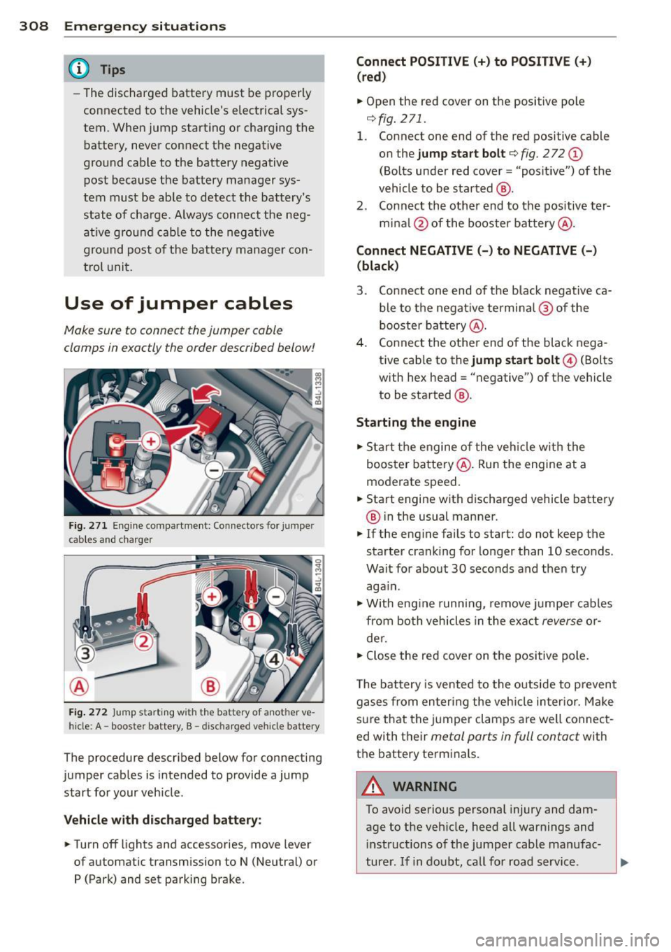
Fig. 271 Eng ine compartme nt: Co nnecto rs fo r jumper
cab les and c harger
®
Fi g. 272 Jump starting with the battery of another ve
hicle: A - booste r battery, B - discha rged vehicle battery
The procedure described below for connecting
jumper cables is intended to provide a jump
start for your veh icle.
Vehicle with discharged b attery :
.. Turn
off lights and accessories, move lever
of automatic transmission to N (Neutral) or
P (Park) and set parking brake. Connect POSITIVE(+) to POSITIVE(+
)
(red )
.. Open the red cover on the positive pole
¢fig. 271.
1. Connect one end of the red positive cable
on the
jump start bolt c::;, fig. 2 72 @
(Bolts under red cover = "positive") of the
vehicle to be started @.
2. Connect th e othe r end to the positive ter-
mi na l@ of the booster batte ry @ .
Connect NEGATIVE (-) to NEGATIVE (-)
(black )
3. Connect one end of the b lack negative ca
ble to the negat ive termi na l@ of the
booster ba ttery @.
4 . Connect the othe r end of the black nega
tive cab le to the
jump start bolt@ (Bolts
with hex head= "negative") of the vehicle
to be started @.
Sta rting the engine
.. Start t he engine o f the veh icle w ith the
booste r ba ttery @. Run the engine at a
moderate speed .
.. Start engine with discharged vehicle battery
@ in the usual manner.
.. If the engine fails to start: do not keep the
starter crank ing for lo nger than 10 seconds.
Wait for about 30 seconds an d the n try
again.
"" With engine running, remove j umpe r cab les
from both vehicles in the exact
reverse o r·
de r .
.. Close the red cover on the positive pole .
T he battery is vente d to the outside to p reven t
gases from entering the veh icle inter ior. M ake
s u re that the j umper clamps are well connec t
ed with their
metal ports in full contact with
the battery term inals.
A WARNING
-
To avoid serious persona l injury and dam-
age to the veh icle, h eed all warnings and
i nstructions of the jumper cable ma nufac-
turer. If in doubt , call for road service. ,..