AUDI Q7 2017 Owner´s Manual
Manufacturer: AUDI, Model Year: 2017, Model line: Q7, Model: AUDI Q7 2017Pages: 402, PDF Size: 100.39 MB
Page 371 of 402
u co ...... N r-... N ...... 0
0
:E: '
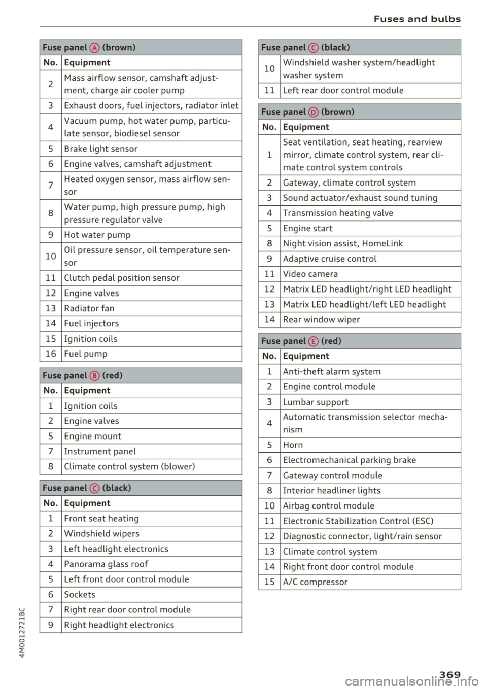
No . Equipment
2
Mass airflow sensor, camshaft adjust-
ment, charge air cooler pump
3 Exhaust doors, fuel injectors, radiator inlet
4 Vacuum pump, hot water pump, particu-
late sensor, biodiesel sensor
5 Brake light sensor
6 Engine va lves, camshaft adjustment
7
Heated oxygen sensor, mass airflow sen-
sor
8
Water pump, high pressure pump, high
pressure regulator va lve
9 Hot water pump
10
Oil pressure sensor, oil temperature sen-
sor
11 Clutch pedal position sensor
12 Engine valves
13 Radiator fan
14 Fuel injectors
15 Ignition coils
16 Fuel pump
Fuse panel @ (red)
No . Equipment
1 Ignition coils
2 Eng ine va lves
5 Engine mount
7 I nstrument pane l
8 Climate control system (blower)
Fuse panel © (black)
No. Equipment
1 Front seat heating
2 Windshield wipers
3 Left headlight electronics
4 Panorama glass roof
5 Left front door control module
6 Sockets
7 Right rear door contro l module
9 Right headlight electronics
Fuses and bulbs
Fuse panel© (black)
10
Windshie ld washer system/headlight
washer system
11 Left rear doo r contro l module
Fuse panel @ (brown)
No . Equipment
Seat ventilation, seat heating, rearview
1 mirror, cl imate control system, rear cli-
mate control system controls
2 Gateway, climate control system
3 Sound actuator/exhaust sound tuning
4 Transmission heating valve
s Engine start
8 Night vision assist, HomeLink
9 Adaptive cruise contro l
11 Video camera
12 Matrix LED headlight/right LED headlight
13 Matrix LED headlight/left LED headlight
14 Rear window wipe r
Fuse panel© (red)
No. Equipment
1 Anti-theft alarm system
2 Engine control module
3 Lumbar support
Automatic transmission selector mecha-
4
nism
s Horn
6 Electromechanical parking brake
7 Gateway control module
8 Inter ior headliner lights
10 A irbag control module
11 Electronic Stabilization Control (ESC)
12 Diagnostic connector, light/ra in sensor
13 Climate control system
14 Right front door control module
15 A/C compressor
369
Page 372 of 402
Fuses and bulbs
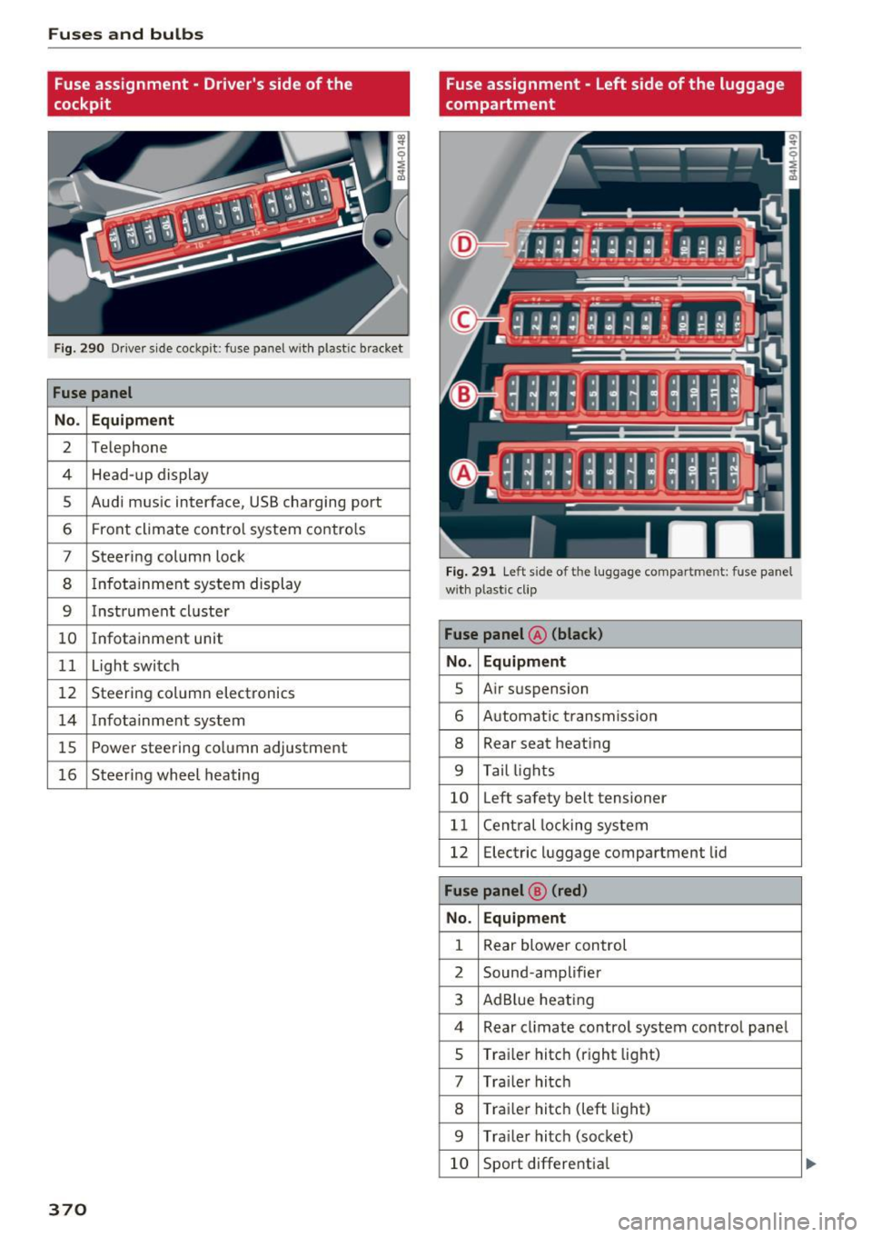
Fuse assignment - Driver's side of the
cockpit
Fig . 290 D river side cockpit: fuse panel wit h plastic bracket
Fuse panel
No . Equipment
2 Te lep hone
4 Head-up display
5 Audi mus ic interface, USB charging port
6 Front climate contro l system contro ls
7 Steering column lock
8 Infotainment system display
9 Instrument cl uster
10 Infotainment unit
11 Light switch
12 Steer ing column electronics
14 Infotainment system
lS Powe
r steering co lumn adjustme nt
1 6 Steer ing wheel heating
370
Fuse assignment - Left side of the luggage
compartment
Fig. 291 L eft side of the lu ggage compartment: fuse panel
wi th plastic cl ip
Fuse panel @ (black)
No. Equipment
5 Air suspension
6 Automat ic t ransmiss ion
8 Rear seat heating
9 Tail lights
10 Left safety belt tensioner
11 Central locking system
12 Electric luggage compartment lid
Fuse panel@ (red)
No . Equipment
1 Rear blower control
2 Sound-amplifier
3 AdBlue heating
4 Rear cl imate contro l system control panel
5 Traile r hitch (right light)
7 Tra iler hitch
8 Trai le r hitch (left light)
9 Trailer hitch (socket)
10 Sport differential
Page 373 of 402
u co .... N r-... N .... 0
0
:E: '
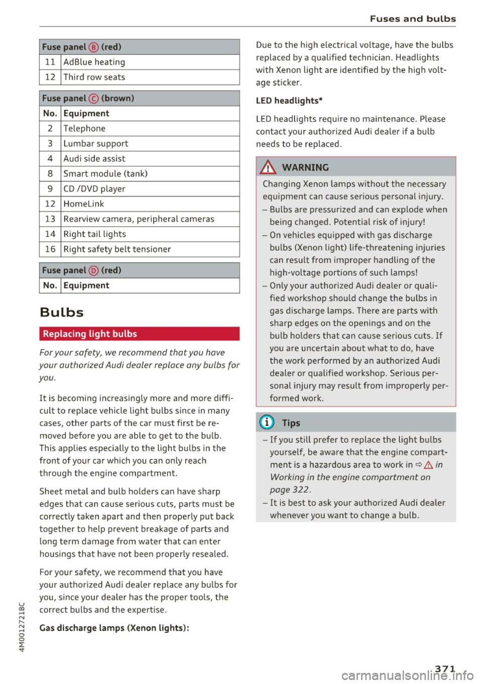
11 AdBlue heating
12 Third row seats
Fuse panel © (brown)
No . Equipment
2 Telephone
3 Lumbar support
4 Audi side assist
8 Smart module (tank)
9 CD /DVD player
12 Homelink
13 Rearview camera, peripheral cameras
14 Right tail lights
16 Right safety belt tensioner
Fuse panel @ (red)
No .
I Equipment
Bulbs
Replacing light bulbs
For your safety, we recommend that you have
your authorized Audi dealer replace any bulbs for
you.
It is becoming increasingly more and more diffi
cult to replace vehicle light bulbs since in many
cases, other parts of the car must first be re
moved before you are able to get to the bulb.
This applies especially to the light bulbs in the
front of your car wh ich you can only reach
through the eng ine compartment.
Sheet metal and bulb ho lders can have sharp
edges that can cause serious cuts, parts must be
correctly taken apart and then properly put back
together to help prevent breakage of parts and long term damage from water that can enter
housings that have not been properly resea led.
For your safety, we recommend that you have
your author ized Audi dealer replace any bulbs for
you, s ince your dealer has the proper tools, the
correct bulbs and the expert ise.
Gas discharge lamps (Xenon lights):
Fuses and bulbs
Due to the high e lectrica l voltage, have the bulbs
rep laced by a qualified technician. Headlights
with Xenon light are identified by the high volt
age sticker.
LED headlights*
LED headlights require no maintenance. Please
contact your authorized Audi dealer if a bulb
needs to be replaced.
& WARNING ~ -
Changing Xenon lamps without the necessary
equipment can cause serious personal injury.
- Bulbs are pressurized and can explode when
being changed . Potential risk of injury!
- On veh icles equipped with gas discharge
bu lbs (Xenon light) life-threatening injuries
can resu lt from improper handling of the
h igh-vo ltage portions of such lamps!
- Only your authorized Audi dealer or quali
fied workshop shou ld change the bulbs in
gas discharge lamps. There are parts with
sharp edges on the openings and on the bulb holders that can cause serious cuts. If
you are uncerta in about what to do, have
the work performed by an authorized Audi deale r or qualified workshop. Ser ious per
sonal injury may result from improperly per
formed work.
(D Tips
-If you st ill prefer to replace the light bulbs
yourself, be awa re that the engine compa rt
ment is a hazardous area to work in~.&..
in
Working in the engine compartment on
page 322.
-It is best to ask your authorized Audi dealer
whenever you want to change a bulb.
371
Page 374 of 402
Emergency situations
Emergency situations
General
This chapter is intended for trained emergency crews and working personnel who have the nec
essary tools and equipment to perform these
operations.
Starting by pushing or
towing
(D Note
Vehicles with an automatic transmission
cannot be started by pushing or towing.
Starting with jumper
cables
If necessary, the engine con be started by con
necting it to the battery of another vehicle.
If the engine should fail to start because of a dis
charged or weak battery, the battery can be con
nected to the battery of
another vehicle, using a
pair of jumper cables to start the engine.
Jumper cables
Use only jumper cables of sufficiently large cross
section
to carry the starter current safely. Refer
to the manufacturer's specifications.
Use only jumper cables with
insulated terminal
clamps which are distinctly marked :
plus(+) cable in most cases colored red
minus(-) cable
in most cases colored black.
A WARNING
Batteries contain electricity, acid, and gas.
Any of these can cause very serious or fatal in
jury. Follow the instructions below for
safe
handling of your vehicle's battery.
-Always shield your eyes and avoid leaning
over the battery whenever possible.
-A dead battery can freeze at temperatures
around 32 °F (0 °C) . If the vehicle battery is
frozen, you must thaw it before connecting
the jump start cables.
If you do not, this in-
372
creases the risk of an explosion and chemi
cal burns. After jump starting the vehicle,
drive to an authorized Audi dealer or author
ized Audi Service Facility immediately to
have the vehicle battery checked.
- Do not allow battery acid to contact eyes or
skin . Flush any contacted area with water
immediately.
- Improper use of a booster battery to start a
vehicle may cause an explosion .
- Vehicle batteries generate explosive gases.
Keep sparks, flame and lighted cigarettes
away from batteries.
- Do not try to jump start any vehicle with a
low acid level in the battery.
- The voltage of the booster battery must also
have a 12-Volt rating. The capacity (Ah) of
the booster battery should not be lower
than that of the discharged battery. Use of
batteries of different voltage or substantial
ly different "Ah" rating may cause an explo
sion and personal injury.
- Never charge a frozen battery. Gas trapped
in the ice may cause an explosion.
- Never charge or use a battery that has been
frozen. The battery case may have be weak
ened.
- Use of batteries of different voltage or sub
stantially different capacity (Ah) rating may
cause an explosion and injury. The capacity (Ah) of the booster battery should not be
lower than that of the discharged battery.
- Before you check anything in the engine
compartment, always read and heed all
WARNINGS
r=:> poge 322.
([) Note
-Applying a higher voltage booster battery
will cause expensive damage to sensitive electronic components, such as control
units, relays, radio, etc.
- There must be no electrical contact between
the vehicles as otherwise current could al
ready start to flow as soon as the positive
(+) terminals are connected.
Page 375 of 402
u (0 ...... N r--. N ...... 0
0
:E
The discharged battery must be properly con
nected to the vehicle's electrical system .
When jump starting or charg ing the battery,
never connect the negative ground cable to
the battery negative post because the battery
manager system must be able to detect the
battery's state of charge. Always connect the
negative ground cable to the negative ground
post of the battery manager control unit.
Using the jump start
cable
Both jump start cables must be connected in the
correct order!
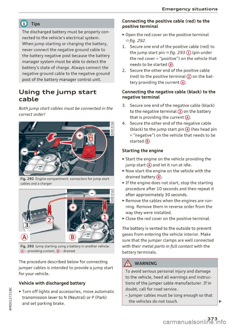
Fig. 292 Engine compartment: connect ors for jump start
cables and a charger
Fig. 293 Ju mp starting us ing a battery in another vehicle:
@ -providing current, @-drained
The procedure described below for connecting
jumper cables is intended to prov ide a jump start
for your vehicle .
Vehicle with discharged battery
•Turnoff lights and accessories, move automatic
transmission lever to N (Neutral) or P (Park)
and set parking brake.
Emergency situations
Connecting the positive cable (red) to the
positive terminal
• Open the red cover on the positive terminal
r=>fig. 292 .
1. Secure one end of the positive cable (red) to
the jump start pin
r=> fig. 293 (D (pin under
the red cover = "posit ive") on the vehicle that
needs to be started @.
2. Secure the other end of the positive cable
(red) to the positive termina l@ on the bat
tery provid ing the current @.
Connecting the negative cable (black) to the
negative terminal
3. Secure one end of the negative cable (black)
to the nega tive term inal @ on the battery
that is providing the current @.
4. Secure the other end of the negative cable
(black) to the jump start pin@ (hex head pin
= "negative") on the vehicle that needs to be
started @.
Starting the engine
• Start the engine on the vehicle providing the
jump start @and let it run at idle.
• Now start the engine on the vehicle with the
drained battery @.
• If the engine does not start, stop the starting
procedure after 10 seconds and then repeat it
after approx imately 30 seconds.
• Remove the cables when the engines are run
ning. Remove them in reverse order from the
way they were installed.
• Close the red cover on the positive terminal.
T he battery is vented to the outside to prevent
gases from enter ing the vehicle interior . Make
sure that the jumper clamps are well connected
with their
metal parts in full contact with the
battery terminals.
_& WARNING
-To avoid serious personal injury and damage to the vehicle, heed all warnings and instruc
tions of the jumper cable manufacturer. If in
doubt, call for road service.
- Jumper cables must be long enough so that
the vehicles do not touch . ..,_
373
Page 376 of 402
Emergency situations
-When connecting jumper cables, make sure
that they cannot get caught in any moving
parts in the engine compartment.
- Do not bend over the batteries -danger of
chemical burns!
- The battery cell locking screws must be
tightened securely.
- Before you check anything in the engine
compartment, always read and heed all
WARNINGS
i=> page 322.
(D Note
Improper hook-up of jumper cables can ruin
the generator.
- Always connect POSITIVE(+) to POSITIVE
(+), and NEGATIVE(-) to NEGATIVE(-)
ground post of the battery manager control
unit.
- Check that all screw p lugs on the battery
cells are screwed in firmly. If not, tighten
plugs prior to connect ing clamp on negative
battery terminal.
- Please note that the procedure for connect
i ng a jumper cable as described above ap
plies specifically to the case of your vehicle
being jump started . When you are giving a
ju mp start to another vehicle, do
not con
nect the negative (-) cable to the negative
(-) terminal on the discharged batte ry @
c> fig. 293. Instead, securely connect the
negative( -) cab le to either a solid metal
component that is firm ly bolted to the en
gine block or to the engine block itself. If
the battery that is being charged does not
vent to the outside, escap ing battery gas
could ignite and explode!
Towing with a tow truck
General hints
Your Audi requires special handling for towing.
The following information is to be used by com
mercial tow truck operators who know how to op
erate the ir equipment safely.
-Never tow your Audi, towing will cause dam
age to the engine and transmission.
374
-Never wrap the safety chains or winch cables
around the brake lines .
- To prevent unnecessary damage, your Audi
must be transported with a flat bed truck .
- To load the vehicle on to the flat bed, use the
towing loop found in the vehicle tools and at
tach to the front or rear anchorage
i=>page 374 and i=>page 375.
A WARNING
A vehicle being towed is not safe for passen
gers. Never allow anyone to ride in a vehicle
being towed, for any reason.
Front towing loop
Only install the front towing loop when it is
needed.
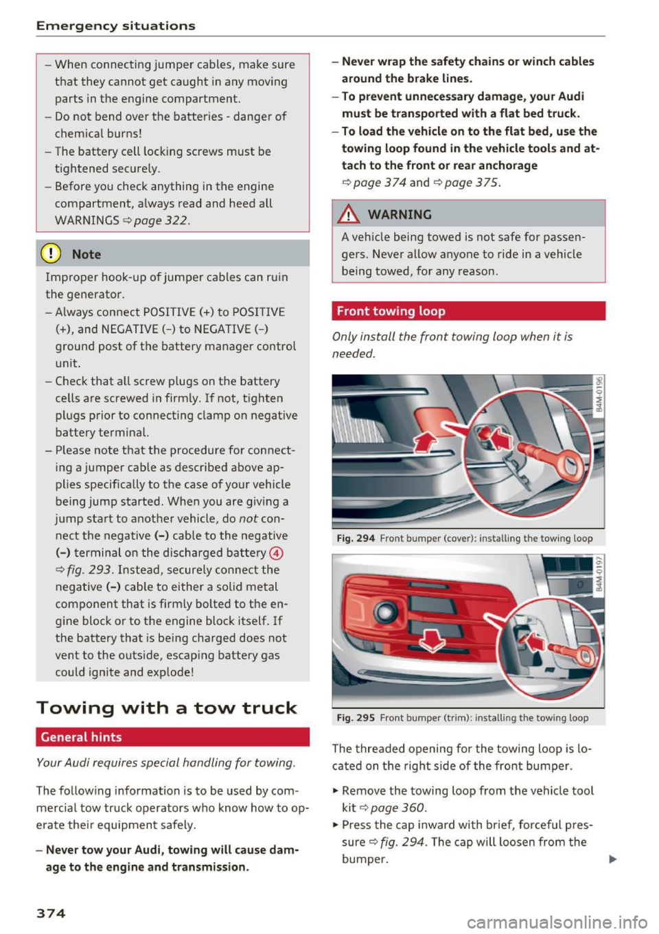
Fig. 294 Front bumper (cover): installing t he tow ing loop
Fig. 29S Front bumper (trim): install ing t he towing loo p
The threaded opening for the towing loop is lo
cated on the right side of the front bumper.
"' Remove the towing loop from the vehicle tool
kit
i=> page 360.
"'Press the cap inward with brief, forceful pres
sure
c> fig. 294. The cap will loosen from the
bumper. ""
Page 377 of 402
u (0 ...... N r--. N ...... 0
0
:E
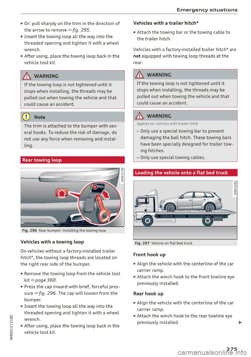
the arrow to remove
c:> fig. 295.
.. Insert the towing loop all the way into the
threaded opening and tighten it with a wheel
wrench .
.. After using, place the towing loop back in the
vehicle tool kit.
_& WARNING
If the towing loop is not tightened unti l it
stops when installing, the threads may be
pulled o ut when towing the vehicle and that
cou ld cause an acc ident .
(D Note
The trim is attached to the bumper with sev
eral hooks. To reduce the risk of damage, do
no t use any force when remov ing and instal
ling .
Rear towing loop
Fig. 296 Rear bumper: installi ng the tow ing loop
Vehicles with a towing loop
On vehicles w ithout a factory-installed trailer
hitch*, the towing loop threads a re located on
the right rear side of the bumper.
-
.,. Remove the tow ing loop from the veh icle tool
k it
c:> page 360 .
.. Press the cap inward wi th brief, forcef ul pres
s ur e
c:>fig. 296. The cap will loosen from the
bumper.
.. Inse rt the towing loop all the way into the
threaded opening and tighten it with a wheel
wrench .
.. After using, place the towing loop back in the
vehicle tool kit.
Emergency situations
Vehicles with a trailer hitch*
.. Attach the towing bar or the towing cable to
the trailer hitch.
Vehicles with a facto ry -installed trailer hitch* are
not equipped with towing loop threads at the
rear.
_& WARNING
If the towing loop is not tightened until it
stops when installing, the threads may be pulled out when towing the vehicle and that
could cause an accident.
_& WARNING
-Applies to: vehicles with trailer hitch
- Only use a spec ial towing bar to prevent
damaging the ball hitch. These towing bars
have been specially designed for trailer tow
i ng hitches.
- Only use special towing cables.
Loading the vehicle onto a flat bed truck
Fig. 297 Vehicle on flat bed truck
Front hook up
.. Align the vehicle with the centerline of the car
carrier ramp .
.,. Attach the w inch hook to the front towline eye
previously installed .
Rear hook up
.. Align the vehicle with the centerline of the car
carrier ramp.
.. Attach the w inch hook to the rear towline eye
previously installed . .,.
375
Page 378 of 402

Emergency situations
@ Tips
Check carefully to make sure the hook-up is
secure before moving the car up the flatbed
truck ramp.
Raising the vehicle
Lifting with workshop hoist and with floor
jack
The vehicle may only be li~ed at the lifting
poin ts illus trated .
Fig . 298 Front lift ing point
Fig . 299 Rear lifti ng po int
• Read and heed WARNING c::> .&_ .
• Locate lifting po ints c::> fig . 298 and ¢ fig. 299.
• Adjus t lifting arms of workshop ho ist o r floo r
ja ck to match veh icle lif ting poin ts.
• Inse rt a rubber pa d between t he f loor jack/
w ork shop hoist and the lifting poin ts.
If you must lift your vehicle with a floor jack to
work underneath , be sure the vehicle is safely
s upported on stands intended for this purpo se.
Front lifting point
The lift ing po int is located on the floor pan re in
forcement about at the same level as the jack
376
moun ting poin t c::> fig. 298 . Do not lift the vehi
cle at the ve rtical sill reinfo rcement.
Rear lifting point
The lifting poin t is lo cated on t he ve rti cal rein
fo rcemen t of t he lower s ill for the onboard j ack
¢fig. 2 99 .
Lifting with vehicle jack
Refer to c::> page 363.
A WARNING
-To r educe th e risk of s erious inju ry an d vehi
cle damage.
- Always lift the vehicle o nly at the special
workshop hoist and f loor jack lift points i l
l ustrated
c::> fig. 298 and c::> fig. 299.
- Failure to lift the ve hicle a t these points
could ca use the vehicle to tilt o r fall from
a lift if there is a change in ve hicle weight
dist ribution and balance . This might hap
pen, fo r example, whe n heavy compo
nen ts su ch as the eng in e b lock o r trans
mi ssion are removed.
- Whe n removing heavy co mponen ts lik e
these, anchor vehicle to hois t or ad d c orre
s p ondin g weights to maintai n the ce nt er of
g ra vity. Oth erw ise, the vehicle mig ht tilt or
slip off the hoist, ca using serio us persona l
in jur y.
(D Note
-Be aw are of the fo ll ow ing poi nts bef ore lift
ing the vehicle:
- The vehicle should never be lifted or
jacked up from underneath the engine oil pan, the transmission hous ing, the front
or rear axle or the body side members.
This could lead to serious damage .
- To avoid damage to the underbody or
chassis frame, a rubber pad must be in
serted between the floor jack and the lift
points.
- Before driving over a workshop hoist,
check that the vehicle weight does not
exceed the permissible lifting capacity of
the hoist. ..,.
Page 379 of 402
u co ...... N r-... N ...... 0
0
:E: '
sure that there is sufficient clearance be
tween the hoist and low parts of the ve
hicle.
Vehicle transport
A ppl ies to: ve hicles with a ir susp en sio n
The following contains information you should
know about transporting your vehicle.
Wh en transporting the vehicle on a ca r ca rri
er, tra in, sh ip or by ot her means , only t ie the
ve hicle down at t he r unnin g surface of the
tires, w hich i s t he outer circumference. Secur
ing the vehicle at the axle components, sus
p ens io n struts or tow ing eyes is no t per mitted
b ecause the pressure in the air suspens io n
str uts ca n cha nge dur in g tra ns port. Th e vehi
cle may no t be se cu red su ffici entl y if this ha p
pe ns.
Emergency situations
377
Page 380 of 402

Technical data
Technical data
Vehicle specifications
Fig. 300 Windsh iel d (fro nt left) : Ve hicl e Iden tific ation
N um ber ( VIN )
XXXXX XX -X -XXXX XXX XX
@-+ ~J:~t::1 ::: xxxxxxxx xx x xxxxxxxx
I YP lf'VPE XXX XXX
XX XXXXXXX XX X X XX
XXX
KW XXX
15\_L I MOIOlll
@-+ ~~
1
:tr:~i XXXX I XXXX XXX I XX
II. -AUSST . / OPTIONS
.__ __
E0A 7D5 4UB
2EH JOZ lLB
3FC
F0 A 9G3
TL6 3 KA 8EH
lXW 803
7T6 CV7 7KO
3L4 4KC
lS A 7GB
6XM SSG
lAS
SMU 7Xl
0G7 0YH
UlA X9B
908 8Z4
4X3 2K2
3Y0 413
01A
SRW
1BA
OJF
027
020
502
4G0
XX X XX X XX X XXXX
Fig . 301 Vehicle identificat ion lab el
Vehicle Identification Number (VIN) in the
Infotainment system
~ Select in the Infotainment system: the I MENU I
button > Vehicle > left contro l button > Service
& checks> Vehicle information.
Vehicle Identification Number (VIN)
The VIN can be found in the Infotainment sys
tem, on the vehicle data label, and under the
windshield on the front left side* <=:>
fig. 300 . The
VIN is also in the right side of the luggage com
partment (the fende r) under a cover.
378
Vehicle identification label
The vehicle identification label <=:> fig. 301 is locat
ed in the luggage compartment under the cargo
floor cover.
The information of the vehicle identification label
can also be found in your Warranty
& Mainte
nance booklet.
The st icker contains the follow ing vehicle data:
(D Vehicle Iden tifica tion Number (VIN)
@ Vehicle type, eng ine output, transmission
® Engine and transmission cod es
@ Paint and interior codes
® Optional equipment numbers
Safety compliance sticker
The safety compliance sticker is your assurance
that your new veh icle complies with all applicable
Federal Motor Vehicle Safety Standards which
were in effect at the time the vehicle was manu
factured. You can find this sticker on the driver's
s id e B-pillar .
It shows the month and year of pro
duction and the vehicl e identification number of
your vehicle (perfo ration) as well as the Gross Ve
hicle Weight Rating (GVWR) and the Gro ss Axle
Weight Rating (GAWR).
H igh voltage warning label
The high voltage warn ing label is located in the
e ngine compartment next to the engine hood re
lease. The spark ignit ion system complies w ith
the Canadian s tand ard IC ES-002.
Notes about technical
data
The values may vary based on special equipment
as well as market-specific equipment and meas
u ring methods.
Please note that the specifications listed in the
vehicle documentation a lways take precedence .
(D Tips
Missing technical data was not available at
the time of printing .