tire pressure AUDI Q7 2020 Owner´s Manual
[x] Cancel search | Manufacturer: AUDI, Model Year: 2020, Model line: Q7, Model: AUDI Q7 2020Pages: 316, PDF Size: 113.87 MB
Page 6 of 316
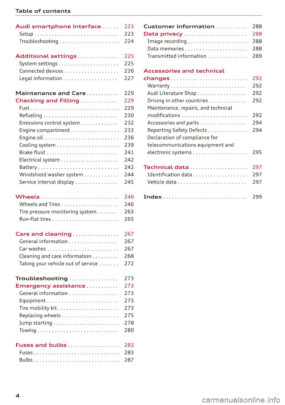
Table of contents
Audi smartphone interface...... Z23,
Setup... eect ee 223
TrOuUBLESHOOtING wees « & wees « 2 eos so eee 224
Additional settings.............. 225
System settingS.......0seeecceeveees 225
Connected devices ...... 0.0... 000 e eee 226
Legalinformation..................5 227
Maintenance and Care........... 229
Checking and Filling............. 229
Fuel... 2. cece eee eee eee eee 229
Refuelingjecs ss sees se ane + eeee § s peme 230
Emissions control system...........4. 232
Engine compartment................. 233
ERGINGOtls seus 2 x seme « ¥ neue =e oRBER Fae 236
Cooling:system . « sscses v < ssesens vo eevee so ave 239
Brake fluid... 2... eee eee eee 241
Electrical SySteMi wis ¢ scm ae mews eg ey 242
Battery: « & cess 6 6 ceva © 5 mews « wenn ¥ © oi 242
Windshield washer system...........- 244
Service interval display............... 245
Wheels ........ 0... eee 246
Wheels and Tires . . 246
Tire pressure monitoring system....... 263
RUMMFLAR EINES: « cose = x once 2m seuse = 0 sees 265
Care and cleaning................ 267
General
information wo. ceo saeco es 267
Car washes...............2..20.00005 267
Cleaning and care information......... 268
Taking your vehicle out of service....... 272
Troubleshooting................. 273
Emergency assistance........... 273
General information................. 273
EQUIPITICNE sass ¢ ¢ eens + eeen a 3 ces 3s He 273
Tire mobility kit ose: <2 cere ae eee se ees 273
Replacing wheels..............000005 275
Jump starting.....................0. 278
TOWING scsvss = ¢ wesos « § eeons & 2 Keres 4 = HES 280
Fuses and bulbs.................. 283
FUSES an + x css 5 © ames + © eRe = Beem He 283
BULDSisi0e svowave 4 6 oniuen a a stants a Hanon w 8 ave 287
Customer information........... 288
Data privacy..................000. 288
Image recording............seeeeeees 288
Datamemoniesy. « s sscams sv sume ov ene a 0s 288
Transmitted information.............. 289
Accessories and technical
CHANGES... 1... eee eee eee 292
Warranty......... 00-000. e eee eee 292
Audi Literature Shop..............00. 292
Driving in other countries............. 292
Maintenance, repairs, and technical
MOGIFIcAatIONS vase x x mem = x saw x 2 sue 292
Accessories and parts................ 294
Reporting Safety Defects.............. 294
Declaration of compliance for
telecommunications equipment and
electronic systems............---0000- 295
Technical data..................8. 297
Identification data................00. 297
Vehicle dataiscs: = s xews 2s eens sp oes ye 297
Index... 0.2... eee 299
Page 11 of 316
4M1012721BA
Quick access
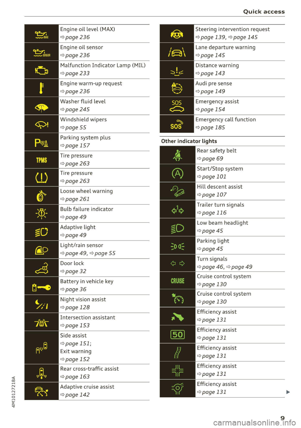
Engine oil level (MAX) Steering intervention request
=> page 236 => page 139, >page 145
Engine oil sensor
=> page 236
Malfunction Indicator Lamp (MIL)
Lane departure warning
=>page 145
Distance warning
=> page 233 => page 143
Engine warm-up request Audi pre sense
=> page 236 =>page 149
Washer fluid level Emergency assist
=>page 245 => page 154
Windshield wipers Emergency call function
=>page 55 =>page 185
Other
indicator lights
Rear safety belt
=> page 69
Parking system plus
=>page 157
Tire pressure
=> page 263
: Start/Stop system
Tire pressure > page 101
=> page 263
Hill descent assist
Loose wheel warning © page 107
=> page 261
5 An Trailer turn signals
Bulb failure indicator
= page 116
= page 49
—— Low beam headlight
Adaptive light >page 45
=> page 49 es : Parking light
Light/rain sensor page 45
= page 49, > page 55 ps Door lock Turn signals
oor loc| => page 46, > page 49
=> page 32
: : Cruise control system
Battery in vehicle key ange 130
=> page 36
Night vision
assist
=> page 128
Cruise control system
=> page 130
Efficiency assist
Intersection assistant => page 131
=> page 153
peg Efficiency assist
Side assist page 131
=> page 151;
P g . Efficiency assist
Exit warning > 131
> page 152 Page
Efficiency assist
> page 131
Rear cross-traffic assist
=> page 163
Adaptive cruise assist | | Efficiency assist
page 142 => page 131 >
Page 69 of 316
4M1012721BA
Sitting correctly and safely
Correct safety belt positioning
B4H-0751
RAZ-0696
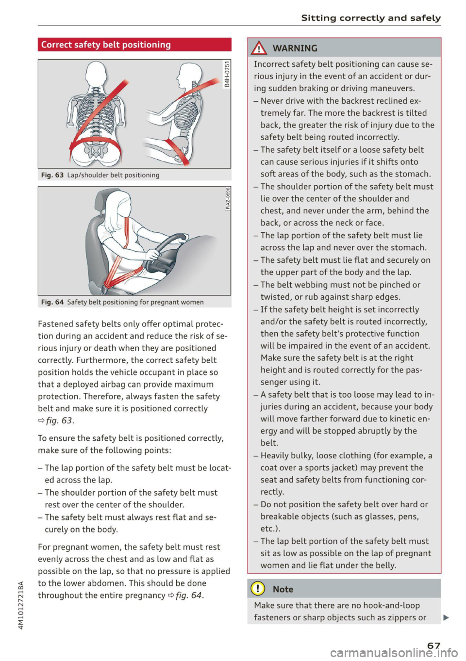
Fastened safety belts only offer optimal protec-
tion during an accident and reduce the risk of se-
rious injury or death when they are positioned
correctly. Furthermore, the correct safety belt
position holds the vehicle occupant in place so
that a deployed airbag can provide maximum
protection. Therefore, always fasten the safety
belt and make sure it is positioned correctly
> fig. 63.
To ensure the safety belt is positioned correctly,
make sure of the following points:
—The lap portion of the safety belt must be locat-
ed across the lap.
—The shoulder portion of the safety belt must
rest over the center of the shoulder.
— The safety belt must always rest flat and se-
curely on the body.
For pregnant women, the safety belt must rest
evenly across the chest and as low and flat as
possible on the lap, so that no pressure is applied
to the lower abdomen. This should be done
throughout the entire pregnancy > fig. 64.
ZA WARNING
Incorrect safety belt positioning can cause se-
rious injury in the event of an accident or dur-
ing sudden braking or driving maneuvers.
— Never drive with the backrest reclined ex-
tremely far. The more the backrest is tilted
back, the greater the risk of injury due to the
safety belt being routed incorrectly.
— The safety belt itself or a loose safety belt
can cause serious injuries if it shifts onto
soft areas of the body, such as the stomach.
— The shoulder portion of the safety belt must
lie over the center of the shoulder and
chest, and never under the arm, behind the
back, or across the neck or face.
— The lap portion of the safety belt must lie
across the lap and never over the stomach.
—The safety belt must lie flat and securely on
the upper part of the body and the lap.
— The belt webbing must not be pinched or
twisted, or rub against sharp edges.
— If the safety belt height is set incorrectly
and/or the safety belt is routed incorrectly,
then the safety belt's protective function
will be impaired in the event of an accident.
Make sure the safety belt is at the right
height and is routed correctly for the pas-
senger using it.
— A safety belt that is too loose may lead to in-
juries during an accident, because your body
will move farther forward due to kinetic en-
ergy and will be stopped abruptly by the
belt.
— Heavily bulky, loose clothing (for example, a
coat over a sports jacket) may prevent the
seat and safety belts from functioning cor-
rectly.
— Do not position the safety belt over hard or
breakable objects (such as glasses, pens,
etc.).
— The lap belt portion of the safety belt must
sit as low as possible on the lap of pregnant
women and lie flat under the belly.
@) Note
Make sure that there are no hook-and-loop
fasteners or sharp objects such as zippers or
67
>
Page 85 of 316
4M1012721BA
Stowing and using
— Never exceed the permitted axle and load
and vehicle weight > page 298.
— Never secure a child safety seat to the tie-
downs.
— Never leave your vehicle unattended, espe-
cially if the luggage compartment lid is
open. Children could enter the luggage com-
partment and close the luggage compart-
ment lid from the inside. This creates the
risk of fatal injury, since the children would
be locked in and may not be able to escape
by themselves.
— Do not allow children to play in or on the ve-
hicle. Close and lock the luggage compart-
ment lid as well as all other doors when you
leave the vehicle.
— Never transport passengers in the luggage
compartment. Every passenger must be cor-
rectly secured with the safety belts in the
vehicle > page 66.
— Be careful when releasing the backrest and
folding
it forward. To reduce the risk of be-
ing pinched, pay attention and check when
folding backrests forward.
— The backrest must be securely latched so
objects cannot slide forward out of the lug-
gage compartment during sudden braking.
— The backrest must be latched securely to en-
sure that the safety belt is protecting the
center seating position.
— Always pull forward on the backrest to make
sure it is check if it is correctly locked in
place.
— Applies to: vehicles with third row seats: To
reduce the risk of injury, the backrest on the
second row seats must be in the upright po-
sition and locked in place if there are pas-
sengers riding in the third row.
— Applies to: vehicles with third row seats:
When there are passengers riding in the
third row seats, remove the adjustable tie-
downs* and place the rail covers on the rails
to
reduce the risk of injuries.
CG) Note
—To reduce the risk of damage, move the rear
head restraints down > page 65 before fold-
ing the rear backrests forward.
— When folding the backrest forward, make
sure the outer safety belts are in the belt
guide recess so that they do not get pinched
in the backrest lock and damaged. Other ob-
jects should be removed from the rear
bench seat to protect the backrest from
damage.
— If you move the front seat back when the
rear seat backrest is folded forward, you
could damage the head restraints on the
rear seat.
— Make sure that the heating grid strips for
the rear window defogger are not damaged
by abrasive objects.
— Let the luggage compartment cover roll up
slowly to reduce the risk of damage.
@) Tips
— The tire pressure must be adapted to the
load > page 256.
— You can purchase straps at specialty stores.
83
Page 102 of 316
Driving
mode. If you turn the engine off, you will not be
able to select any other gears after restarting the
engine. Drive to an authorized Audi dealer or au-
thorized Audi Service Facility immediately to have
the malfunction corrected.
fi Selector lever: malfunction! You can contin-
ue driving. Please contact Service
There is a system malfunction in the selector lev-
er. Drive immediately to an authorized Audi deal-
er or authorized Audi Service Facility to have the
malfunction repaired.
| Selector lever: malfunction! Gear change on-
ly possible if using both shift paddles.
There is a system malfunction in the selector lev-
er. You can continue driving with restricted func-
tion. The selector lever is not working. Gears can
only be selected by tapping both shift paddles at
the same time when the vehicle is stationary. The
“P” gear is automatically engaged when you turn
off the engine. Drive to an authorized Audi dealer
or authorized Audi Service Facility immediately to
have the malfunction corrected.
fs} P button: malfunction! Auto P when engine
off. Please contact Service
There is a malfunction in the "P" button on the
selector lever. The “P” gear is automatically en-
gaged when you turn off the engine. Drive to an
authorized Audi dealer or authorized Audi Service
Facility immediately to have the malfunction cor-
rected.
fs} Danger of rolling away! P not possible.
Please apply parking brake
The parking lock was released using the emer-
gency release > page 98 or can no longer be en-
gaged. Drive to an authorized Audi dealer or au-
thorized Audi Service Facility immediately to have
the malfunction corrected.
Move selector lever to automatic position
The transmission has switched out of tiptronic
mode. Switch back to automatic mode with the
selector lever > page 98.
100
Drive system
A new vehicle must be broken in within the first
1,000 miles (1,500 km) so that all moving parts
work smoothly together, which helps to increase
the service life of the engine and other drive com-
ponents.
Do not drive higher than two-thirds of the maxi-
mum permitted engine RPM during the first 600
miles (1,000 km) and do not use full accelera-
tion. The engine can be increased RPM gradually
during the next 300 miles (500 km).
(eT eee LL Maal Meas Ms LENS Alla)
Applies to: vehicles with a conventional drive system or a mild
hybrid drive system
Vehicles with a conventional or mild hybrid drive
system are powered by a combustion engine. It
uses fuel to recover energy.
Vehicles with a mild hybrid drive system have ad-
ditional battery technology.
airless Ned e(aeLN
driving
Your driving style greatly influences the amount
of fuel and energy consumed, the environmental
impact, and the wear on the engine, brakes, and
tires. Note the following information for efficient
and environmentally-conscious driving:
— Turn off electrical equipment that is not need-
ed, for example seat heating*.
— Anticipate upcoming traffic situations while
driving to avoid unnecessary acceleration and
braking.
— Avoid driving at high speeds.
— Avoid adding extra weight to the vehicle if pos-
sible, for example by not leaving roof racks or
bike racks installed when they are not needed.
— Make sure the tire pressure is correct.
— Have maintenance performed regularly on the
vehicle.
— Do not drive with winter tires during the summ-
er.
Page 111 of 316
4M1012721BA
Driving dynamic
Based on the selected setting, the air suspen-
sion* will adjust the ground clearance and the ac-
tive roll stabilization* will provide various de-
grees of compensation for vehicle movements.
Engine sound
The engine sound adapts and can be subtle to
sporty.
Suspension
XCEL Melia Ley
Applies to: vehicles with suspension control
The adaptive dampers are an electronically-con-
trolled damping system. The firmness of the sus-
pension will adapt to the driving conditions and
the driving situation. The settings depend on the
selected Audi drive select* mode.
Air suspension
Applies to: vehicles with air suspension
The air suspension is an electronically-controlled
suspension and leveling system. The firmness of
the suspension will adapt to the driving condi-
tions and the driving situation. The system balan-
ces out changes in load. The vehicle level will also
adapt gradually to the vehicle speed in order to
reduce the wind resistance at high speeds and in-
crease the ground clearance at low speeds. The
settings depend on the selected Audi drive se-
lect* mode.
Displaying the vehicle level
» Applies to MMI: Select on the home screen: VE-
HICLE > Audi drive select.
The filled-in boxes represent the current vehicle
level. The more boxes that are filled in, the high-
er the ground clearance. The box that corre-
sponds with the current vehicle level will flash
while the vehicle is lifting or lowering. The target
level is indicated by a red outline.
Raising the vehicle
> Applies to MMI: Select on the home screen: VE-
HICLE > Audi drive select.
> Press Raise to reach the highest vehicle level
and thus the maximum ground clearance.
> Press Lower to lower the vehicle down again.
The Audi drive select* mode will be changed if
necessary when the vehicle is raised.
The vehicle will lower at speeds of approximately
20 mph (30 km/h) and below. This function may
only be used temporarily when increased ground
clearance is necessary. It is not intended for long
drives.
() Note
—Also refer to the information about ground
clearance > page 109.
— When transporting the vehicle on a road
carrier, rail carrier, ship carrier, or other car-
rier, it may only be secured at the running
surfaces of the tires (circumference). Secur-
ing the vehicle at the axle components, sus-
pension struts, or towing eyes is not permit-
ted because the pressure in the air suspen-
sion struts can change during transport. The
vehicle might not be secured sufficiently if
this happens.
Ground clearance
The vehicle height and clearance can be influ-
enced by the following factors:
— Change in temperature
— Change in load
— Change to the Audi drive select* mode
— Lifting and lowering via the air suspension*
— Lower the rear* of the vehicle
ZA WARNING
To reduce the risk of injury, make sure no one
gets pinched when the vehicle level is chang-
ing, for example when cleaning the under-
body or the wheel housings.
() Note
Always make sure there is enough clearance
above and below the vehicle. This is especially
important for entrances with height restric-
tions, for example, before driving into under-
ground garages. You could also scrape the
ground when driving over the edges of curbs
109
>
Page 118 of 316

Trailer towing
correctly will help to achieve this weight. Having
the tongue weight too low affects the vehicle's
handling.
You can determine the tongue weight using a
tongue weight scale, a bathroom scale, or a pub-
lic weigh station, for example.
The permitted tongue weight of your vehicle can
be found in the vehicle documentation or in
=> page 298.
Load distribution
Poor cargo load and distribution can negatively
impact vehicle handling. Load the trailer based
on the following criteria as much as possible:
— Store objects in the vehicle luggage compart-
ment, if possible. The vehicle should always
carry the heaviest possible load and the trailer
should have the lightest possible load.
— Distribute the load in the trailer so that the
heavy objects are as close to the axle as possi-
ble.
— Secure objects so that they do not slide.
— Utilize the maximum permitted tongue weight
if possible.
Tires
Set the tire pressure on your vehicle for a “full
load”; see the tire pressure sticker > page 256. If
necessary, also adjust the tire pressure on the
trailer according to the manufacturer's specifica-
tions.
The tire pressure must be increased an additional
3 PSI (0.2 bar) for towing loads over 6,600 lbs
(3,000 kg).
The trailer and the vehicle should be equipped
with winter tires when driving in winter tempera-
tures.
Outside mirrors
If you cannot see the traffic behind the trailer
with the standard exterior mirrors, then you
must attach additional exterior mirrors. Adjust
them so you have a sufficient visibility behind
you.
116
Exterior lighting
Follow the legal regulations for lighting on your
trailer that are applicable in the country where
you are operating the vehicle. Contact an author-
ized Audi dealer or authorized Audi Service Facili-
ty for more information.
Before you start driving, check all lighting equip-
ment on the trailer while it is hitched to the vehi-
cle.
The headlight range control automatically ad-
justs the light range of the headlights.
The turn signals are activated in trailer mode if
the & indicator light blinks. If a turn signal on
the trailer or on the vehicle fails while in trailer
mode, the indicator light will not blink twice as
fast to indicate this.
Safety chains
Make sure the safety chains are correctly applied
when pulling a trailer. The chains should hang
enough so that the trailer can drive around
curves. However, they must not touch the
ground.
Air suspension
Applies to: vehicles with air suspension
The Audi drive select* comfort mode > page 108
must be selected before you adjust the tongue
weight on the trailer and hitch the trailer >,
=> page 109.
For vehicles with a factory-installed trailer hitch,
the air suspension trailer mode will automatically
switch on if you connect the trailer cable to the
socket.
For vehicles with a retrofitted trailer hitch, you
must switch on the air suspension trailer mode
manually.
Applies to MMI: select on the home screen: VE-
HICLE > Settings & Service > Air suspension:
trailer.
Switch it off again when you are no longer towing
a trailer.
When using carrier systems that are mounted di-
rectly on the trailer hitch ball head, you can also
switch trailer mode off manually.
Page 250 of 316
Wheels
@ US DOT number (TIN) and
manufacture date
The manufacture date is listed on
the tire sidewall (it may only ap-
pear on the inner side of the tire):
DOT... 2219...
means, for example, that the tire
was produced in the 22nd week of
the year 2019.
@) Audi Original Tires
Audi Original equipment tires
with the designation “AO” have
been specially matched to your
Audi. When used correctly, these
tires meet the highest standards
for safety and handling. An au-
thorized Audi dealer or author-
ized Audi Service Facility will be
able to provide you with more in-
formation.
@) Mud and snow capability
“M/S” or “M+S” indicates the tire
is suitable for driving on mud and
snow. /\ indicates a winter tire.
Composition of the tire cord
and materials
The number of plies indicates the
number of rubberized fabric lay-
ers in the tire. In general: the
more layers, the more weight a
tire can carry. Tire manufacturers
248
must also specify the materials
used in the tire. These include
steel, nylon, polyester and other
materials.
@) Maximum permitted load
This number indicates the maxi-
mum load in kilograms and
pounds that the tire can carry.
@ Uniform tire quality grade
standards for treadwear,
traction and temperature
resistance
Treadwear, traction, and tempera-
ture ranges > page 263.
@ Running direction
The arrows indicate the running
direction of unidirectional tires.
You must always follow the speci-
fied running direction
=> page 278.
Maximum permitted
inflation pressure
This number indicates the maxi-
mum pressure to which a tire can
be inflated under normal operat-
ing conditions.
Page 251 of 316
4M1012721BA
Wheels
Glossary of tire and loading
terminology
Accessory weight
means the combined weight (in
excess of those standard items
which may be replaced) of auto-
matic transmission, power steer-
ing, power brakes, power win-
dows, power seats, radio, and
heater, to the extent that these
items are available as factory-in-
stalled equipment (whether in-
stalled or not).
Aspect ratio
means the ratio of the height to
the width of the tire in percent.
Numbers of 55 or lower indicate a
low sidewall for improved steer-
ing response and better overall
handling on dry pavement.
Bead
means the part of the tire that is
made of steel wires, wrapped or
reinforced by ply cords and that is
shaped to fit the rim.
Bead separation
means a breakdown of the bond
between components in the bead.
Cord
means the strands forming the
plies in the tire.
Cold tire inflation pressure
means the tire pressure recom-
mended by the vehicle manufac-
turer for a tire of a designated
size that has not been driven for
more than a couple of miles (kilo-
meters) at low speeds in the three
hour period before the tire pres-
sure is measured or adjusted.
Curb weight
means the weight of a motor ve-
hicle with standard equipment in-
cluding the maximum capacity of
fuel, oil, and coolant, air condi-
tioning and additional weight of
optional equipment.
Extra load tire
means a tire designed to operate
at higher loads and at higher in-
flation pressures than the corre-
sponding standard tire. Extra load
tires may be identified as “XL”,
“xL’, “EXTRA LOAD”, or “RF” on
the sidewall.
249
Page 252 of 316

Wheels
Gross Axle Weight Rating
(“GAWR’”)
means the load-carrying capacity
of a single axle system, measured
at the tire-ground interfaces.
Gross Vehicle Weight Rating
(“GVWR”)
means the maximum total loaded
weight of the vehicle.
Groove
means the space between two ad-
jacent tread ribs.
Load rating (code)
means the maximum load that a
tire is rated to carry for a given in-
flation pressure. You may not find
this information on all tires be-
cause it is not required by law.
Maximum load rating
means the load rating for a tire at
the maximum permissible infla-
tion pressure for that tire.
Maximum loaded vehicle
weight
means the sum of:
(a) Curb weight
(b) Accessory weight
(c) Vehicle capacity weight, and
(d) Production options weight
250
Maximum (permissible)
inflation pressure
means the maximum cold infla-
tion pressure to which a tire may
be inflated. Also called “maxi-
mum inflation pressure.”
Normal occupant weight
means 150 lbs. (68 kilograms)
times the number of occupants
seated in the vehicle up to the to-
tal seating capacity of your vehi-
cle.
Occupant distribution
means distribution of occupants
in a vehicle.
Outer diameter
means the overall diameter of an
inflated new tire.
Overall width
means the linear distance be-
tween the exteriors of the side-
walls of an inflated tire, including
elevations due to labeling, deco-
rations, or protective bands or
ribs.
Ply
means a layer of rubber-coated
parallel cords.