mirror AUDI Q7 2021 Owner´s Manual
[x] Cancel search | Manufacturer: AUDI, Model Year: 2021, Model line: Q7, Model: AUDI Q7 2021Pages: 332, PDF Size: 117.99 MB
Page 123 of 332
4M1012721BC
Trailer towing
in the trailer correctly will help to achieve this
weight. Having the tongue weight too low affects
the vehicle's handling.
You can determine the tongue weight using a
tongue weight scale, a bathroom scale, or a pub-
lic weigh station, for example.
The permitted tongue weight of your vehicle can
be found in the vehicle documentation or in
=> page 314.
Load distribution
Poor cargo load and distribution can negatively
impact vehicle handling. Load the trailer based
on the following criteria as much as possible:
— Store objects in the vehicle luggage compart-
ment, if possible. The vehicle should always
carry the heaviest possible load and the trailer
should have the lightest possible load.
— Distribute the load in the trailer so that the
heavy objects are as close to the axle as possi-
ble.
— Secure objects so that they do not slide.
— Utilize the maximum permitted tongue weight
if possible.
Tires
Set the tire pressure on your vehicle for a “full
load”; see the tire pressure sticker > page 269. If
necessary, also adjust the tire pressure on the
trailer according to the manufacturer's specifica-
tions.
The tire pressure must be increased an additional
3 PSI (0.2 bar) for towing loads over 6,600 lbs
(3,000 kg).
The trailer and the vehicle should be equipped
with winter tires when driving in winter tempera-
tures.
Outside mirrors
If you cannot see the traffic behind the trailer
with the standard exterior mirrors, then you
must attach additional exterior mirrors. Adjust
them so you have a sufficient visibility behind
you.
Exterior lighting
Follow the legal regulations for lighting on your
trailer that are applicable in the country where
you are operating the vehicle. Contact an author-
ized Audi dealer or authorized Audi Service Facili-
ty for more information.
Before you start driving, check all lighting equip-
ment on the trailer while it is hitched to the vehi-
cle.
The headlight range control automatically ad-
justs the light range of the headlights.
The turn signals are activated in trailer mode if
the B indicator light blinks. If a turn signal on
the trailer or on the vehicle fails while in trailer
mode, the indicator light will not blink twice as
fast to indicate this.
Safety chains
Make sure the safety chains are correctly applied
when pulling a trailer. The chains should hang
enough so that the trailer can drive around
curves. However, they must not touch the
ground.
Air suspension
Applies to: vehicles with air suspension
The Audi drive select* comfort mode > page 113
must be selected before you adjust the tongue
weight on the trailer and hitch the trailer >,
=> page 114.
The air suspension trailer mode must be switched
on.
Applies to MMI: select on the home screen: VE-
HICLE > Settings & Service > Air suspension:
trailer.
Switch trailer mode off again when you are no
longer towing a trailer.
For vehicles with a factory-installed trailer hitch,
the air suspension trailer mode will automatically
switch on if you connect the trailer connector to
the socket.
When using rear carrier systems that are mount-
ed directly on the trailer hitch ball head, you can
also switch trailer mode off manually.
121
Page 127 of 332
4M1012721BC
Assist systems
with limitations may not be detected at all.
Always monitor the traffic and the vehicle's
surroundings directly and do not become dis-
tracted.
@) Note
— Obstacles may disappear from the measure-
ment range when approaching them, even if
they were already detected.
—Insome situations, the ability of the sen-
sors and cameras to detect and display cer-
tain objects may be limited.
— Objects located above the coverage area,
such as bumpers on parked cars, garage
doors that are partially open, or objects
that are hanging
— Low obstacles
— Narrow objects, such as barrier chains, fo-
liage, poles, or fences
— Projecting objects, such as trailer draw
bars
— Objects with certain surfaces and struc-
tures, such as fabric
@ Tips
— The sensors and cameras and the areas
around them must not be obstructed be-
cause this can impair the function of the
systems that depend on them. Make sure
that the sensors and cameras are free of
snow, ice, and other deposits. Do not use
any accessories, stickers, or other objects
that extend into the range of the sensors
and cameras.
— On vehicles that have factory-installed li-
cense plate brackets on the front of the ve-
hicle, the brackets may only be replaced
with ones that are the same size and made
of the same material. Do not install any li-
cense plate brackets on the front of vehicles
that do not have factory-installed brackets.
Otherwise, the function of the system could
be impaired.
— The function of the sensors and cameras
may be limited when light and visibility con-
ditions are poor, for example when driving
into a tunnel, when there is glare, or when
there are reflective objects.
— External ultrasonic sensors, such as those in
other vehicles, can interfere with the sen-
sors.
—The coverage areas of the sensors > fig. 93
and cameras > fig. 94 are diagrams and do
not represent a true-to-scale image of the
sensor ranges.
— The system complies with United States FCC
regulations and ISED regulations
=> page 311.
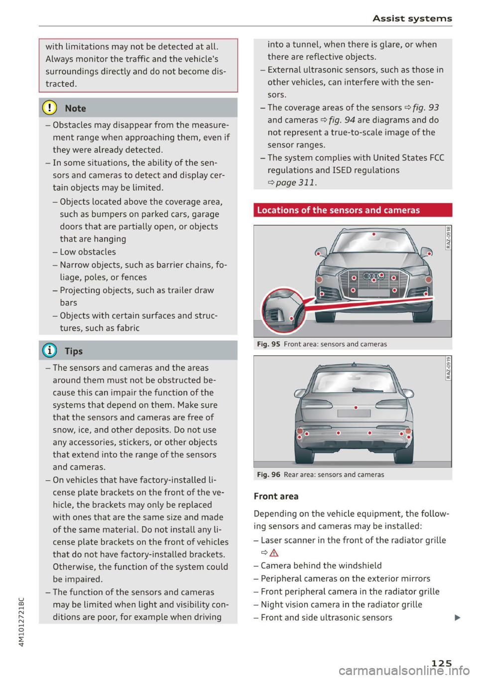
Locations of the sensors and cameras
Fig. 96 Rear area: sensors and cameras
Front area
Depending on the vehicle equipment, the follow-
ing sensors and cameras may be installed:
— Laser scanner in the front of the radiator grille
oA
— Camera behind the windshield
— Peripheral cameras on the exterior mirrors
— Front peripheral camera in the radiator grille
— Night vision camera in the radiator grille
— Front and side ultrasonic sensors
125
Page 136 of 332

Driving information
The Sli symbol will appear when pedestrian and
wild animal detection is not available.
Marking light*
To direct the driver's attention to a pedestrian,
the headlights can flash on the pedestrian when
there is a pedestrian warning.
This occurs at speeds above approximately
35 mph (60 km/h) if you are outside of illuminat-
ed areas and no detected vehicles are shown. The
marking light is not used for wild animals. The
high beam assistant* controls the marking
light*> page 51.
Adjusting the contrast
Applies to: vehicles with night vision assist
Requirement: the night vision assist must be
switched on and the % tab must be displayed.
» Applies to MMI: Select on the home screen: VE-
HICLE > Driver assistance > (£23) > Night vision
assist.
> To set the desired contrast, move the slider.
Messages
Applies to: vehicles with night vision assist
Night vision assist: currently unavailable.
See owner's manual
The system is not functioning correctly at the
time, so it has been switched off. If the malfunc-
tion persists, drive immediately to an authorized
Audi dealer or authorized Audi Service Facility to
have the malfunction repaired.
Integrated Toll Module
Applies to: vehicles with Integrated Toll Module
Depending on the region, you can pay toll fees in
certain countries using the Integrated Toll Mod-
ule (ITM). It replaces a separate transponder for
detecting toll fees. The system electronics are in-
tegrated in the rearview mirror housing.
To use the ITM in toll zones, you must register
and activate it.
134
Registration
> Applies to MMI: Select on the home screen: VE-
HICLE > Settings & Service > Vehicle informa-
tion Toll module.
> Note the Integrated Toll Module ID.
> To register the ITM, go to the displayed web ad-
dress and follow the instructions.
Activation
> To activate the ITM, press CD in the MMI.
Entering the number of passengers
Depending on the number of passengers and the
region, a lower toll fee may be charged. You must
either enter the number of passengers or deacti-
vate the ITM based on the laws applicable in the
area where you are driving.
> To enter the number of passengers, select the
appropriate button in the MMI.
> To deactivate the ITM, press @ in the MMI.
(i) Tips
— The driver is responsible for specifying the
correct number of passengers and activat-
ing or deactivating the ITM.
— Malfunctions can occur when detecting tolls
if both the ITM and transponder are activat-
ed. Deactivate the system not being used or
remove it as necessary.
—Ifa rearview mirror is replaced, you must
register the new ITM and remove the old
ITM from the account.
— The system complies with United States FCC
regulations and ISED regulations
> page 311.
Display
Applies to: vehicles with Integrated Toll Module
The selected number of passengers is displayed
in the MMI status bar > page 22.
The i symbol in the status bar and a notifica-
tion in the MMI will indicate if there is a faulty
connection between the ITM and the MMI or if
the ITM is faulty. If the connection interference
continues or the ITM is faulty, drive immediately >
Page 157 of 332
4M1012721BC
Driver assistance
@ Tips
— If the system is switched off, it switches on
again automatically once the ignition is
switched on again.
— Switch Audi pre sense off when you are not
using public streets, when loading the vehi-
cle onto a vehicle carrier, train, ship, or oth-
er type of transportation, or when towing
the vehicle. This can help to prevent an un-
desired intervention from the Audi pre
sense system.
Messages
Applies to: vehicles with Audi pre sense
If BJ is displayed when there is a malfunction,
the Audi pre sense functions may be unavailable
or may be limited.
A message that indicates the cause and possible
solution may appear with some displays. The
weather conditions may be too poor or a sensor
may be covered. Bring the vehicle to a full stop,
switch the ignition off, and clean the area in front
of the sensors > page 125.
If the message still appears after switching the
ignition on again, have an authorized repair facili-
ty correct the malfunction as soon as possible.
D In certain countries.
Side assist
petted aCoy a)
Applies to: vehicles with side assist
al 3 a z
e|
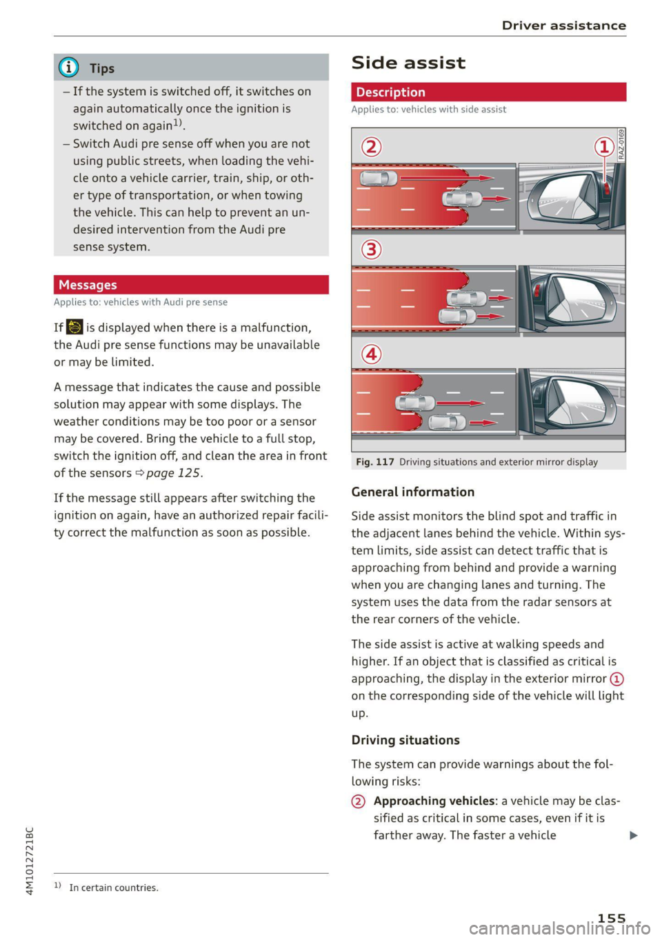
Fig. 117 Driving situations and exterior mirror display
General information
Side assist monitors the blind spot and traffic in
the adjacent lanes behind the vehicle. Within sys-
tem limits, side assist can detect traffic that is
approaching from behind and provide a warning
when you are changing lanes and turning. The
system uses the data from the radar sensors at
the rear corners of the vehicle.
The side assist is active at walking speeds and
higher. If an object that is classified as critical is
approaching, the display in the exterior mirror @)
on the corresponding side of the vehicle will light
up.
Driving situations
The system can provide warnings about the fol-
lowing risks:
@ Approaching vehicles: a vehicle may be clas-
sified as critical in some cases, even if it is
farther away. The faster a vehicle
155
Page 158 of 332

Driver assistance
approaches, the sooner the display will turn
on.
@ Vehicles traveling in the same direction: the
display will turn on if vehicles traveling in the
same direction as your vehicle are classified
as critical. The side assist warns you of all de-
tected vehicles when they are in the “blind
spot” or before they reach that point.
@ Vehicles you are passing: the display only
turns on if you slowly pass a detected vehicle
(difference in speed between the two vehicles
is less than 9 mph (15 km/h)). There is no
display if you pass a vehicle more quickly.
Information stage
At the information level, the side assist informs
you of detected objects that are classified as criti-
cal. This is even possible when your vehicle is sta-
tionary and the turn signal is turned on, so that
the system can also assist you when turning.
From speeds of approximately 6 mph (10 km/h)
and higher, the system will warn you of detected
objects that are classified as critical, even if the
turn signal is not turned on.
The display remains dim in the information stage
so that you are not distracted while looking for-
ward.
Warning stage
If you activate a turn signal and the display flash-
es, side assist is warning about objects that have
been classified as critical.
Depending on the vehicle equipment and other
driver assistance systems, the display may also
flash if you have not activated a turn signal. If
you are approaching a detected lane marker line
and it appears you will be leaving the lane, the
display will warn you about detected vehicles
that are classified as critical. You can also be
warned with corrective steering > page 149,
Lane departure warning.
Detection range
The radar sensors are designed to detect the left
and right adjacent lanes when the road lanes are
the normal width. In some situations, the display
may turn on even though there is no vehicle lo-
156
cated in the area that is critical for a lane change.
For example:
— If the lanes are narrow or if you are driving on
the edge of your lane. If this is the case, the
system may have detected a vehicle in another
lane that is not adjacent to your current lane.
—If you are driving through a curve. Side assist
may react to a vehicle that is in the same lane
or one lane over from the adjacent lane.
— If side assist reacts to other objects (such as
roadside structures like guard rails).
ZA WARNING
— Observe the safety precautions and note the
limits of the assist systems, sensors, and
cameras > page 123.
— The display may not appear on time when
vehicles are approaching or being passed
very quickly.
G) Tips
— If the window glass in the driver's door or
front passenger's door has been tinted, the
display in the exterior mirror may be incor-
rect.
— These systems are not available in trailer
towing mode. There is no guarantee the sys-
tems will switch off when using a retrofitted
trailer hitch. Do not use these functions
when towing a trailer.
— The coverage areas of the sensors > fig. 117
are diagrams and do not represent a true-
to-scale image of the sensor ranges.
— The system complies with United States FCC
regulations and ISED regulations
=> page 311.
Peet
Applies to: vehicles with side assist
The system can be switched on and off in the
MMI & page 126. If the system is activated, the
displays will turn on briefly when the ignition is
switched on.
Page 159 of 332

4M1012721BC
Driver assistance
Adjusting the brightness
You can adjust the brightness of the display in
the exterior mirror. The settings depend on the
vehicle equipment.
> Applies to: MMI: Select on the home screen:
VEHICLE > Driver assistance > (<23) > Side as-
sist > Brightness.
The display brightness is automatically adapted
to the ambient light. If the automatic adaptation
has already reached the upper or lower limit, no
change will be apparent when the setting is
changed, or it will only become visible when the
ambient light changes. Adjust the brightness to a
level where the display in the information stage
will not disrupt your view ahead. If you change
the brightness, the display will briefly show the
brightness level in the information stage.
Messages
Applies to: vehicles with side assist
iff or ig is displayed when there is a malfunc-
tion, the side assist and exit warning system
functions may be unavailable or may be limited.
A message that indicates the cause and possible
solution may appear with some displays. The
weather conditions may be too poor or a sensor
may be covered. Clean the sensor area at the rear
corners of the vehicle > page 125, fig. 96 and try
to turn the systems on again later.
If the malfunction remains, drive to an author-
ized Audi dealer or authorized Audi Service Facili-
ty immediately to have the malfunction correct-
ed.
Exit warning
Applies to: vehicles with exit warning system
Fig. 119 Front door: warning strip
General information
Within system limits, the exit warning system
can detect traffic approaching from behind such
as vehicles, and provide assistance based on this
information when you are exiting the vehicle
=> fig. 118. The system uses the data from the ra-
dar sensors at the rear corners of the vehicle.
Displays and warnings
If you pull a door handle while the vehicle is sta-
tionary and an object classified as critical is ap-
proaching, the warning strip @ and the display
on the exterior mirror (2) will light up on the cor-
responding side of the vehicle.
If the door is opened, the displays on that side
will flash. If another road user that is classified
as critical is approaching while a door is already
open, the displays on that door will turn on.
The same messages apply for the exit warning
system and side assist > page 157.
157
Page 167 of 332
4M1012721BC
Parking and maneuvering
> Move the window wiper lever S7 into the posi-
tion for cleaning the rear window & & page 58.
ZA WARNING
Observe the safety precautions and note the
limits of the assist systems, sensors, and
cameras > page 123.
Warnings
Applies to: vehicles with rearview camera/peripheral cameras
Applies to: vehicles with trailer view
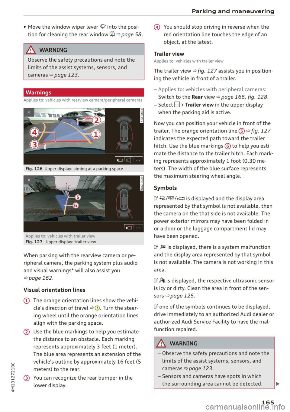
Fig. 127 Upper display: trailer view
When parking with the rearview camera or pe-
ripheral camera, the parking system plus audio
and visual warnings* will also assist you
=> page 162.
Visual orientation lines
@ The orange orientation lines show the vehi-
cle's direction of travel >@. Turn the steer-
ing wheel until the orange orientation lines
align with the parking space.
@ Use the blue markings to help you estimate
the distance to an obstacle. Each marking
represents approximately 3 feet (1 meter).
The blue area represents an extension of the
vehicle's outline by approximately 16 feet (5
meters) to the rear.
@® You can recognize the rear bumper in the
lower display.
@ You should stop driving in reverse when the
red orientation line touches the edge of an
object, at the latest.
Trailer view
Applies to: vehicles with trailer view
The trailer view > fig. 127 assists you in position-
ing the vehicle in front of a trailer.
— Applies to: vehicles with peripheral cameras:
Switch to the Rear view > page 166, fig. 128.
— Select |---| > Trailer view in the upper display
when the parking aid is active.
Now you can position your vehicle in front of the
trailer. The orange orientation line G) ° fig. 127
indicates the expected path toward the trailer
hitch. Use the blue markings © to help you esti-
mate the distance to the trailer hitch. Each mark-
ing represents approximately 1 foot (0.30 me-
ters). The width of the blue surface represents
the maximum steering wheel angle.
Symbols
If $2/&9/< is displayed and the display area
represented by that symbol is not available, then
the camera on the that side is not available. The
power exterior mirrors may have been folded in
or a door or the luggage compartment lid may
have been opened.
If # is displayed, there is a system malfunction
and the display area represented by that symbol
is not available. The camera is not working in this
area.
If Avis displayed, the respective ultrasonic sensor
is icy or dirty. Clean the area in front of the sen-
sors > page 125.
If one of the symbols continues to be displayed,
drive immediately to an authorized Audi dealer or
authorized Audi Service Facility to have the mal-
function repaired.
A WARNING
— Observe the safety precautions and note the
limits of the assist systems, sensors, and
cameras > page 123.
— Sensors and cameras have spots in which
the surrounding area cannot be detected. >
165
Page 168 of 332
Parking and maneuvering
Objects, animals, and people may only be
detected with limitations may not be detect-
ed at all. Always monitor the traffic and the
vehicle's surroundings directly and do not
become distracted.
@) Note
— The orange orientation lines @) show the di-
rection the rear of the vehicle will be travel-
ing, based on the steering wheel angle. The
front of the vehicle swings out more than
the rear of the vehicle. Maintain plenty of
distance so that an exterior mirror or a cor-
ner of the vehicle does not collide with any
obstacles.
— Keep enough distance from the curb to
avoid damage to the rims.
— Only use the images provided by the camera
on the rear of the vehicle when the luggage
compartment lid is completely closed. Make
sure any objects you may have mounted on
the luggage compartment lid do not block
the rearview camera.
G) Tips
— Applies to vehicles with air suspension: The
accuracy of the orientation lines and blue
surfaces on the camera display decreases
when the vehicle is raised or lowered with
the air suspension.
— There is no distance warning for the rear
and the sides* when trailer towing mode is
detected. The front sensors remain activat-
ed. The visual display switches to trailer
mode. There is no guarantee the functions
will be deactivated when using a retrofitted
trailer hitch.
Operating the peripheral cameras
Applies to: vehicles with peripheral cameras
E
3
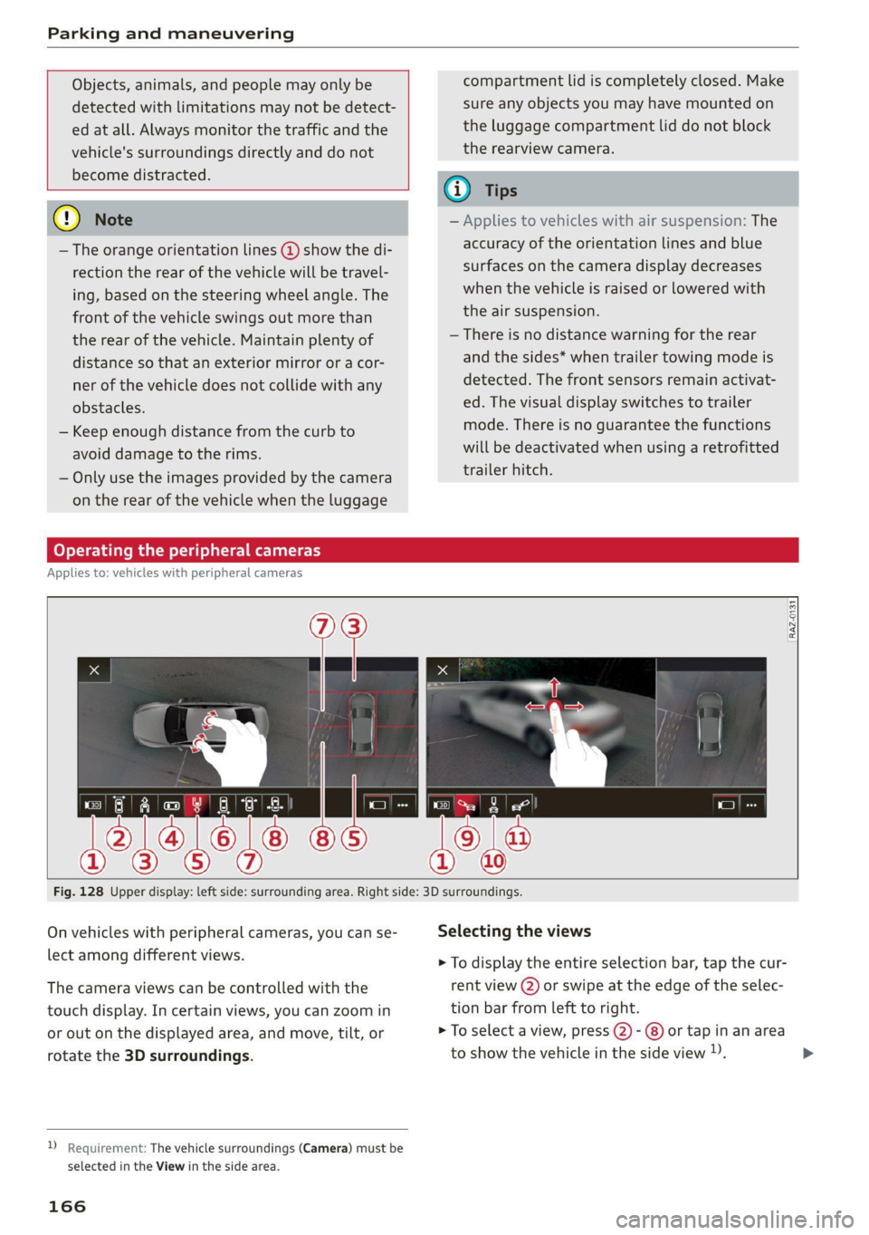
Fig. 128 Upper display: left side: surrounding area. Right side: 3D surroundings.
On vehicles with peripheral cameras, you can se- Selecting the views
lect among different views. > To display the entire selection bar, tap the cur-
The camera views can be controlled with the rent view (2) or swipe at the edge of the selec-
touch display. In certain views, you can zoom in tion bar from left to right.
or out on the displayed area, and move, tilt, or > To select a view, press (2)- @) or tap in an area
rotate the 3D surroundings. to show the vehicle in the side view )). >
2 Requirement: The vehicle surroundings (Camera) must be
selected in the View in the side area.
166
Page 283 of 332

4M1012721BC
Care and cleaning
A WARNING height and width of the inside of the car
wash.
—To reduce the risk of accidents, only wash
the vehicle when the ignition is off and fol-
low the instructions from the car wash oper-
ator.
—To reduce the risk of paint damage, do not
wash the vehicle in direct sunlight.
—To reduce the risk of damage, do not wash
decorative decals* with a pressure washer.
—To reduce the risk of damage to the surface,
do not use insect removing sponges, kitchen
sponges, or similar items.
— When washing matte finish painted vehicle
components:
—To reduce the risk of cuts, protect yourself
from sharp metal components when wash-
ing the underbody or the inside of the wheel
housings.
— After washing the vehicle, the braking effect
may be delayed due to moisture on the
brake rotors or ice in the winter. This in-
creases the risk of an accident. The brakes
must be dried with a few careful brake appli-
cations.
— To reduce the risk of damage to the sur-
face, do not use polishing agents or hard
wax.
— Never use protective wax. It can destroy
the matte finish effect.
@) Note — Do not place any stickers or magnetic
signs on vehicle components painted with
matte finish paint. The paint could be
damaged when the stickers or magnets
are removed.
— If you wash the vehicle in an automatic car
wash, you must fold the exterior mirrors in
to reduce the risk of damage to the mirrors.
Power folding exterior mirrors* must only
be folded in and out using the power folding (@) For the sake of the environment
function.
—To reduce the risk of damage to the rims
and tires, compare the width between the
wheels on your vehicle with the distance be-
tween the guide rails in the car wash.
Only wash the vehicle in facilities specially de-
signed for that purpose. This will reduce the
risk of dirty water contaminated with oil from
entering the sewer system.
—To reduce the risk of damage, compare the
height and width of your vehicle with the
Cleaning and care information
When cleaning and caring for individual vehicle are not listed, consult an authorized Audi dealer
components, refer to the following tables. The or authorized Audi Service Facility. Also follow
information contained there is simply recommen- __ the information found in > A.
dations. For questions or for components that
Exterior cleaning
Component Situation Solution
Windshield wiper | Deposits Soft cloth with glass cleaner, > page 60
blades
Headlights/ Deposits Soft sponge with a mild soap solution®
tail lights
Sensors/ Deposits Sensors: soft cloth with a solvent-free cleaning product
camera lenses Camera lenses: soft cloth with an alcohol-free cleaning sol-
ution
Snow/ice Hand brush/solvent-free de-icing spray >
281
Page 286 of 332

Care and cleaning
— Never clean the headlights or tail lights
with a dry cloth or sponge because the
lights could be damaged.
— Do not use any cleaning products that con-
tain alcohol, because they could cause
cracks to form.
— Wheels
— Never use any paint polish or other abra-
sive materials.
— Damage to the protective layer on the
rims, such as stone chips or scratches,
must be repaired immediately.
— Camera lenses
— Never use warm or hot water to remove
snow or ice from the camera lens. This
could cause the lens to crack.
— Never use abrasive cleaning materials or
alcohol to clean the camera lens. This
could cause scratches and cracks.
— Laser scanner
— Never use abrasive cleaning materials to
clean the laser scanner. This could cause
scratches and cracks.
— Door windows
— Remove snow and ice on windows and ex-
terior mirrors with a plastic scraper. To re-
duce the risk of scratches, move the scra-
per only in one direction and not back and
forth.
— Never remove snow or ice from door win-
dows and mirrors using warm or hot water
because this could cause cracks to form.
—To reduce the risk of damage to the rear
window defogger, do not apply any stick-
ers on the heating wires on the inside of
the window.
— Decorative parts and trim
— Never use chrome care or cleaning prod-
ucts.
— Paint
— To reduce the risk of scratches, the vehicle
must be free of dirt and dust before pol-
ishing or waxing.
—To prevent paint damage, do not polish or
wax the vehicle in direct sunlight.
—To reduce the risk of paint damage, do not
polish away rust spots.
284
— Remove cosmetics and sunscreen immedi-
ately because they could damage the
paint.
— Decorative decals
—To reduce the risk of damage, do not use
any rough powder or abrasive cleaning
products.
— To reduce the risk of damage, do not pol-
ish decorative decals that have a matte or
printed finish.
— Due to the risk of damage, do not use an
ice scraper to remove snow and ice on win-
dows with decorative decals on them.
— Displays and instrument cluster
— Make sure that the display and instrument
cluster are switched off and have cooled
down before cleaning. To switch off the
upper and lower display, select on the
MMI home screen: SETTINGS > Display &
brightness > MMI > Screen cleaning.
— Displays, the instrument cluster, and the
trim surrounding it must not be cleaned
with dry cleaning methods because they
could become scratched.
— Make sure no fluids enter the spaces be-
tween the instrument cluster and the
trim, because that could cause damage.
— Controls
— Make sure that no fluids enter the con-
trols, because this could cause damage.
— Safety belts
— Do not remove the safety belts to clean
them.
— Never clean safety belts or their compo-
nents with chemicals or with corrosive flu-
ids or solvents and never allow sharp ob-
jects to come into contact with the safety
belts. This could cause damage to the belt
webbing.
—If there is damage to the webbing, the
connections, the retractors, or the buck-
les, have them replaced by an authorized
Audi dealer or authorized Audi Service Fa-
cility.
— Textiles, artificial leather, and Alcantara
— Never treat artificial leather or Alcantara
with leather care products, solvents, floor >