12 volt AUDI R8 2007 Owners Manual
[x] Cancel search | Manufacturer: AUDI, Model Year: 2007, Model line: R8, Model: AUDI R8 2007Pages: 210, PDF Size: 8.1 MB
Page 12 of 210
Instruments and warning/indicator lamps 10Instruments and warning/indicator lampsInstrumentsInstrument cluster overview
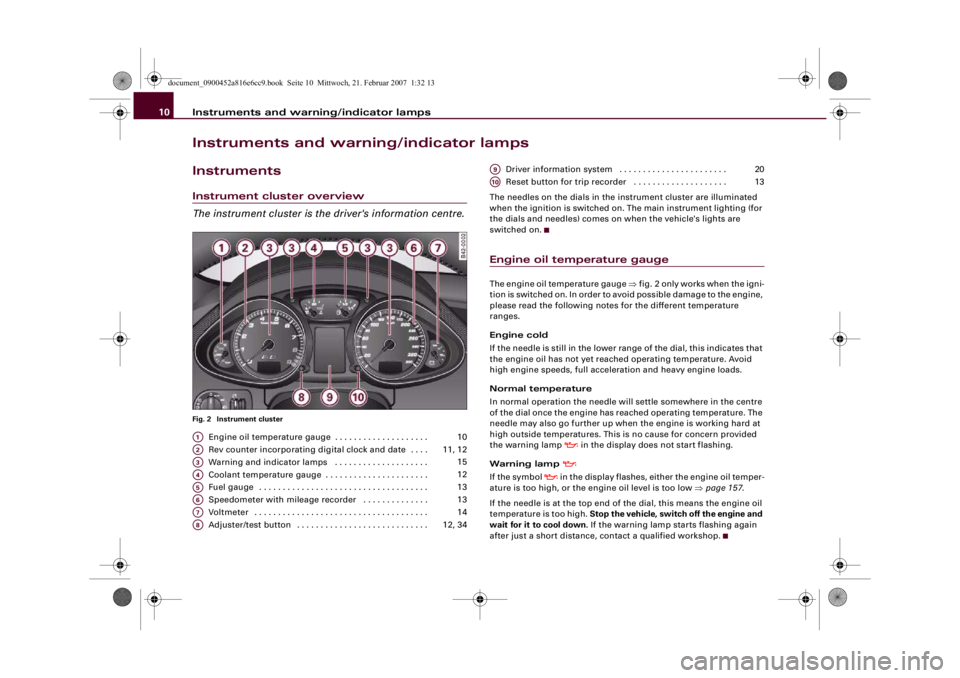
The instrument cluster is the driver's information centre.Fig. 2 Instrument cluster
Engine oil temperature gauge . . . . . . . . . . . . . . . . . . . .
Rev counter incorporating digital clock and date . . . .
Warning and indicator lamps . . . . . . . . . . . . . . . . . . . .
Coolant temperature gauge . . . . . . . . . . . . . . . . . . . . . .
Fuel gauge . . . . . . . . . . . . . . . . . . . . . . . . . . . . . . . . . . . .
Speedometer with mileage recorder . . . . . . . . . . . . . .
Voltmeter . . . . . . . . . . . . . . . . . . . . . . . . . . . . . . . . . . . . .
Adjuster/test button . . . . . . . . . . . . . . . . . . . . . . . . . . . . Driver information system . . . . . . . . . . . . . . . . . . . . . . .
Reset button for trip recorder . . . . . . . . . . . . . . . . . . . .
The needles on the dials in the instrument cluster are illuminated
when the ignition is switched on. The main instrument lighting (for
the dials and needles) comes on when the vehicle's lights are
switched on.
Engine oil temperature gaugeThe engine oil temperature gauge ⇒fig. 2 only works when the igni-
tion is switched on. In order to avoid possible damage to the engine,
please read the following notes for the different temperature
ranges.
Engine cold
If the needle is still in the lower range of the dial, this indicates that
the engine oil has not yet reached operating temperature. Avoid
high engine speeds, full acceleration and heavy engine loads.
Normal temperature
In normal operation the needle will settle somewhere in the centre
of the dial once the engine has reached operating temperature. The
needle may also go further up when the engine is working hard at
high outside temperatures. This is no cause for concern provided
the warning lamp
in the display does not start flashing.
Warning lamp
If the symbol
in the display flashes, either the engine oil temper-
ature is too high, or the engine oil level is too low ⇒page 157.
If the needle is at the top end of the dial, this means the engine oil
temperature is too high. Stop the vehicle, switch off the engine and
wait for it to cool down. If the warning lamp starts flashing again
after just a short distance, contact a qualified workshop.
A1
10
A2
11, 12
A3
15
A4
12
A5
13
A6
13
A7
14
A8
12, 34
A9
20
A10
13
document_0900452a816e6cc9.book Seite 10 Mittwoch, 21. Februar 2007 1:32 13
Page 16 of 210
Instruments and warning/indicator lamps 14Upper mileage recorder (trip recorder)
The upper mileage recorder shows the distance that has been trav-
elled since the trip recorder was last reset. It is used to measure indi-
vidual journeys. The last digit of the trip recorder indicates
distances of 100 metres or tenths of a mile. The trip recorder can be
reset to zero by pressing the reset button ⇒page 13, fig. 5.
When the ignition is switched off, the illumination of the mileage
recorder can be switched on for a few seconds by pressing the
adjuster/test button ⇒page 10, fig. 2 .
Fault display
If there is a fault in the instruments, the letters dEF appear perma-
nently in the trip recorder display. Please have the fault rectified as
soon as possible.
Immobiliser
When the ignition is switched on, the security programming of the
ignition key is verified electronically.
If an uncoded key is used, SAFE will appear continuously in the trip
recorder display. The vehicle cannot then be driven ⇒page 42.Voltmeter displayThe voltmeter indicates the voltage of the vehicle's electrical
system. The voltage of the electrical system should normally be
between 12 and 14 volts. If the display drops below 12 volts when
the engine is running, have the power supply (battery and alter-
nator) checked by a qualified workshop.
Note
The voltage may drop below 8 volts while the engine is being
started.
A8
document_0900452a816e6cc9.book Seite 14 Mittwoch, 21. Februar 2007 1:32 13
Page 36 of 210
Driver information system 34Yellow symbols are accompanied by one warning chime. The func-
tion indicated should be checked as soon as possible. If several
faults are detected at the same time, the symbols are displayed one
after the other for about 2 seconds at a time.
Driver messages
Additional messages to assist the driver are displayed in
conjunction with the warning lamps and symbols in the
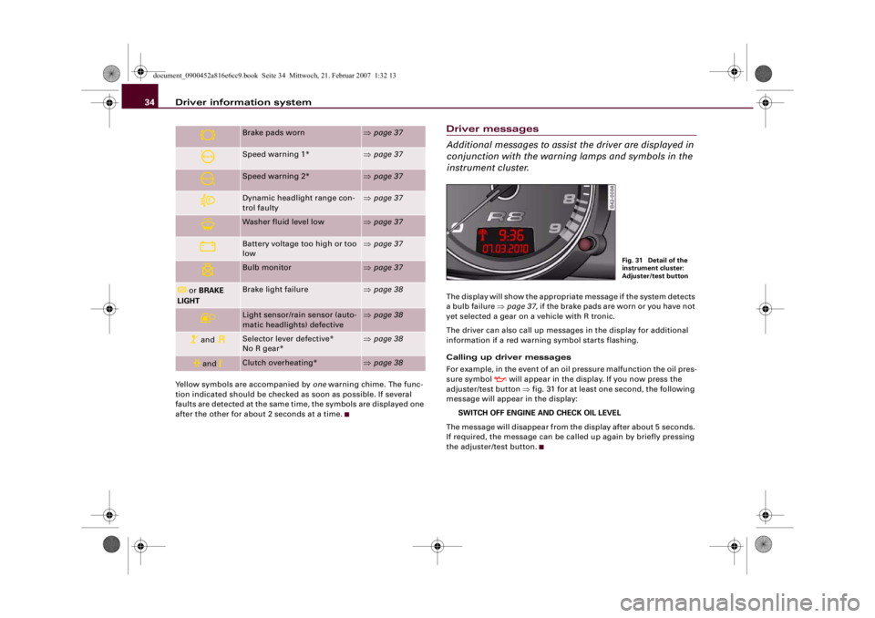
instrument cluster.The display will show the appropriate message if the system detects
a bulb failure ⇒page 37, if the brake pads are worn or you have not
yet selected a gear on a vehicle with R tronic.
The driver can also call up messages in the display for additional
information if a red warning symbol starts flashing.
Calling up driver messages
For example, in the event of an oil pressure malfunction the oil pres-
sure symbol
will appear in the display. If you now press the
adjuster/test button ⇒fig. 31 for at least one second, the following
message will appear in the display:
SWITCH OFF ENGINE AND CHECK OIL LEVEL
The message will disappear from the display after about 5 seconds.
If required, the message can be called up again by briefly pressing
the adjuster/test button.
Brake pads worn
⇒page 37
Speed warning 1*
⇒page 37
Speed warning 2*
⇒page 37
Dynamic headlight range con-
trol faulty
⇒page 37
Washer fluid level low
⇒page 37
Battery voltage too high or too
low
⇒page 37
Bulb monitor
⇒page 37
or BRAKE
LIGHT
Brake light failure
⇒page 38
Light sensor/rain sensor (auto-
matic headlights) defective
⇒page 38
and
Selector lever defective*
No R gear*
⇒page 38
and
Clutch overheating*
⇒page 38
Fig. 31 Detail of the
instrument cluster:
Adjuster/test button
document_0900452a816e6cc9.book Seite 34 Mittwoch, 21. Februar 2007 1:32 13
Page 39 of 210
Driver information system37
Controls
Safety
Driving tips
General maintenance
Self-help
Technical data
Check engine oil level
Please check oil level
If the symbol lights up, add 1 litre of oil at the next opportunity
⇒page 158.
Engine oil sensor defective
If the
symbol lights up, take the vehicle to a qualified workshop
and have the oil level sensor checked.
Front brake pads worn
If the
symbol lights up, have the front brake pads (and, for
safety's sake the rear pads as well) inspected by a qualified
workshop.
Speed warning 1
If the
symbol lights up, this means you are exceeding the speed
that has been pre-set with the speed warning function. You should
reduce your speed accordingly ⇒page 31.
Speed warning 2
If the
symbol lights up, this means you are exceeding the speed
that has been pre-set for speed warning 2. You should reduce your
speed accordingly ⇒page 31.
Headlight range control defective
This symbol
indicates a malfunction in the dynamic headlight
range control. Take the vehicle to a qualified workshop to have the
dynamic headlight range control function repaired.
Washer fluid level low
If the
symbol lights up, top up the fluid for the windscreen
washer and headlight washer system ⇒page 164.
Battery voltage too high or too low
If the
symbol lights up, take the vehicle to a qualified workshop
and have the following items checked:
•
Poly-V belt
•
Battery condition
It is also advisable to check whether the alternator warning lamp
has come on ⇒page 18.
Bulb monitor
The bulb monitor checks whether the lights on the vehicle
are working.If a defective bulb is detected, or if one of the lights has failed for
any reason, the bulb monitor symbol
will appear in the display
together with an additional message (which goes out after
5 seconds). For instance, if the rear left turn signal is not working,
the display in the instrument cluster will show the following
message:
REAR LEFT TURN SIGNAL
document_0900452a816e6cc9.book Seite 37 Mittwoch, 21. Februar 2007 1:32 13
Page 40 of 210
Driver information system 38The message disappears after 5 seconds. Press the adjuster/test
button ⇒page 10, fig. 2 briefly if you wish to call up the message
again.
If the display indicates that one of the lights is not working, this can
have a number of causes:•
Bulb failure ⇒page 193.
•
A “blown” fuse ⇒page 190, “Changing fuses”.
•
Defective electrical wiring.
Have the components replaced or the wiring repaired as necessary
by a qualified workshop.
WARNING
•
Bulbs are sensitive to pressure. The glass can break when you
touch the bulb, causing injury.
•
Incorrect handling of the high-voltage element of xenon gas-
discharge bulbs can have potentially fatal consequences.
Brake light failure
If the symbol
or the text BRAKE LIGHT lights up, check the
following components:
•
Brake light bulbs
•
Wiring connections
•
Brake light switch
Have the components repaired or replaced by a qualified workshop.Note
The brake light switch is only tested during the initial systems check
after starting the engine.
Applies to vehicles: with light sensor/ rain sensorLight sensor/rain sensor
This indicator lamp comes on if the automatic headlights/
automatic wipers are defective.If the
symbol appears, this means that the light sensor/ rain
sensor is not functioning. For safety reasons, the dipped beam
headlights will then be switched on permanently when the light
switch is set to the AUTO position. However, you can still switch the
lights on and off in the normal way with the light switch. If the rain
sensor is defective, the functions operated via the windscreen wiper
lever will still be available. You should have the light sensor/ rain
sensor checked by a qualified workshop as soon as possible.
Applies to vehicles: with R tronicSelector lever defective
and
Selector lever defective! No R gear!
If these symbols light up, there is a fault in the R tronic selector
lever. The indicators on the selector lever will go out or flash. It is no
longer possible to engage reverse gear. If you were using the
gearbox in manual mode, it will switch back to automatic mode.
You can continue to change gear manually. Starting in neutral (N),
pull the paddle lever on the steering wheel to engage first gear.
The gearbox will now remain in manual mode and you can select the
gears using the paddle levers.
You should have the selector lever checked by a qualified workshop
as soon as possible.
Applies to vehicles: with R tronicClutch overheating
and
Clutch is overheating ! If possible please stop vehicle.
A8
A+
document_0900452a816e6cc9.book Seite 38 Mittwoch, 21. Februar 2007 1:32 13
Page 74 of 210
Seats and storage 72Cup holders
WARNING
•
Do not put any hot drinks in the cup holders while the vehicle
is moving. You could be scalded if the hot liquid is spilt.
•
Do not use hard china cups or glasses. These could cause injury
in the event of an accident.Caution
You should avoid putting open drinks containers in the cup holders.
The drinks could otherwise spill over and cause damage to e.g. the
electrical equipment or the seat covers.
AshtrayOpening ashtray
– Lift the cover.
Removing ashtray
– Open the cover all the way to the right.
– Take out the ashtray.
Inserting ashtray
– Insert the ashtray and press it into its mountings.
WARNING
Never put waste paper in the ashtray, as this could cause a fire.Cigarette lighter and electrical socketThe 12 Volt socket for the cigarette lighter can also be
used as a power source for other electrical appliances.The cigarette lighter and electrical socket only work when
the ignition is on.
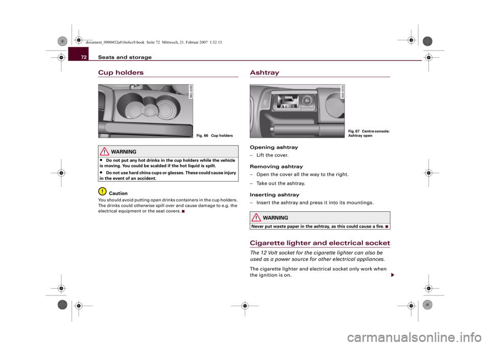
Fig. 66 Cup holders
Fig. 67 Centre console:
Ashtray open
document_0900452a816e6cc9.book Seite 72 Mittwoch, 21. Februar 2007 1:32 13
Page 75 of 210
Seats and storage73
Controls
Safety
Driving tips
General maintenance
Self-help
Technical data
Using cigarette lighter
– Open the ashtray cover to access the cigarette lighter
⇒page 72.
– Press in the cigarette lighter knob.
– Wait for the lighter to spring out.
– Pull out the cigarette lighter immediately.
– Use the glowing heater element of the cigarette lighter to
light your cigarette.
– Put the cigarette lighter back in its socket.
Operating electrical socket
– Open the cover to access the cigarette lighter.
– Take out the cigarette lighter.
– Insert the plug of the electrical appliance into the ciga-
rette lighter socket.The cigarette lighter employs a standard 12 Volt socket which can
also be used as a power source for electrical appliances. The appli-
ances connected to the socket must not exceed a power rating of
100 W.
WARNING
Take care when using the cigarette lighter. Carelessness or negli-
gence when using the cigarette lighter can cause burns.
Caution
Always use the correct type of plugs to avoid damaging the sockets.
Note
Using electrical appliances with the engine switched off will drain
the battery.Storage compartmentsGlove box
The lockable glove box is equipped with a light.Opening glove box
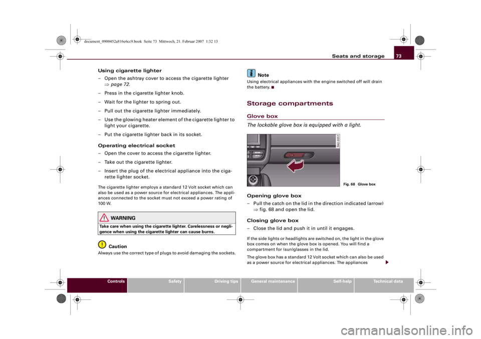
– Pull the catch on the lid in the direction indicated (arrow)
⇒fig. 68 and open the lid.
Closing glove box
– Close the lid and push it in until it engages.If the side lights or headlights are switched on, the light in the glove
box comes on when the glove box is opened. You will find a
compartment for (sun)glasses in the lid.
The glove box has a standard 12 Volt socket which can also be used
as a power source for electrical appliances. The appliances
Fig. 68 Glove box
document_0900452a816e6cc9.book Seite 73 Mittwoch, 21. Februar 2007 1:32 13
Page 158 of 210
Checking and topping up fluids 156drive belts and alternator, etc., and from the high-voltage ignition
system. •
Observe the following additional warnings if work on the fuel
system or the electrical system is necessary:
−Always disconnect the battery
−Do not smoke
−Never work near open flames
−Always keep an approved fire extinguisher immediately
available.Caution
When topping up fluids make sure the correct fluid is put into the
correct filler opening. This can otherwise cause serious malfunc-
tions or engine damage.
For the sake of the environment
Inspect the ground underneath your vehicle regularly so that any
leaks are detected at an early stage. If you find oil spots or other
fluids, have your vehicle inspected by a qualified workshop.
Note
On right-hand drive vehicles* some of the containers/ reservoirs
mentioned below are located on the other side of the engine
compartment.Closing the engine lid– Make sure that the rear spoiler is retracted ⇒page 134.
– To close the engine lid, pull it down to overcome the
spring pressure.– Then let it drop into the catches; do not press down ⇒.
WARNING
For safety reasons the engine lid must always be completely
closed when the vehicle is moving. After closing it always check
that it is properly secured. The engine lid must be flush with the
adjacent body panels.Engine compartment layout
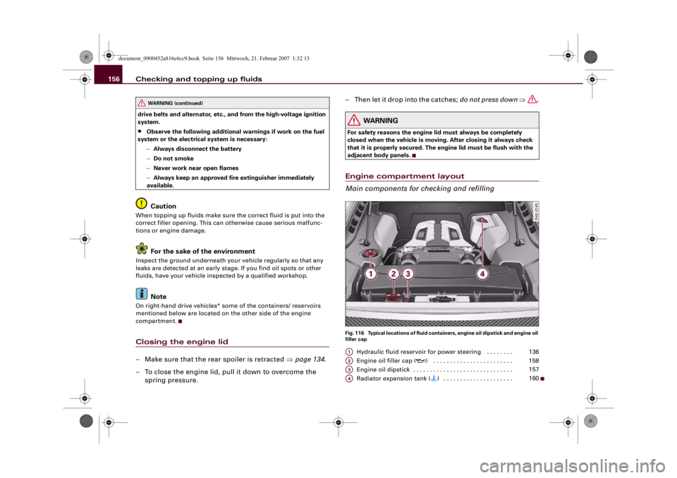
Main components for checking and refillingFig. 116 Typical locations of fluid containers, engine oil dipstick and engine oil
filler cap
Hydraulic fluid reservoir for power steering . . . . . . . .
Engine oil filler cap (
) . . . . . . . . . . . . . . . . . . . . . . . .
Engine oil dipstick . . . . . . . . . . . . . . . . . . . . . . . . . . . . . .
Radiator expansion tank () . . . . . . . . . . . . . . . . . . . . .
WARNING (continued)
A1
136
A2
158
A3
157
A4
160
document_0900452a816e6cc9.book Seite 156 Mittwoch, 21. Februar 2007 1:32 13
Page 164 of 210
Checking and topping up fluids 162BatteryGeneral notes
All work on batteries requires specialist knowledge.The battery is located behind the cover in the luggage compart-
ment. To remove the cover, slide it to the left and lift it out.
The battery is virtually maintenance-free and is checked in the
Inspection Services.
We recommend that you replace a battery once it is older than 5
years.
Disconnecting the battery
If the battery is disconnected, some of the vehicle's functions will
become inoperative (e.g. electric windows). These functions will
require resetting after the battery is reconnected. For this reason,
the battery should only be disconnected from the vehicle's electrical
system when absolutely necessary.
If the vehicle is not used for long periods
The battery will gradually lose its charge because certain electrical
equipment continues to draw current even when the ignition is off.
If you park the vehicle for long periods of time in winter you should
have your Audi R8 dealer take the battery out of the vehicle and keep
it in a frost-proof room. This ensures that it cannot “freeze up” and
be damaged. At warm outside temperatures it is sufficient to
disconnect the negative terminal of the battery. Even when the
battery is not connected you should charge it from time to time.
Winter conditions
The battery is drained more in cold weather, which means that the
starting power is reduced. For this reason, have the battery checked
and charged if necessary before the start of winter.Replacing the battery
A replacement battery must have the same capacity, voltage and
current rating. It must also have the same dimensions as the orig-
inal, factory-fitted battery and have sealed caps. The Audi batteries
which have been specially developed fulfil the maintenance,
performance and safety specifications for your vehicle.
We recommend to use only maintenance-free batteries or deep-
cycle resistant and leakproof batteries which comply with the
standards TL 825 06 (dated December 1997 or later) and VW 7 50 73
(August 2001 or later).
Since the battery is difficult to access, we recommend having it
replaced by an Audi R8 dealer or qualified workshop.
WARNING
•
All work on batteries requires specialist knowledge. For queries
regarding the vehicle battery please contact an Audi R8 dealership
or other qualified workshop (risk of chemical burns / risk of explo-
sion).
•
The battery must not be opened. Do not attempt to make any
changes to the electrolyte level of the battery. Otherwise, there is
a risk that a mixture of oxygen and hydrogen gas can accumulate
and cause an explosion.Caution
•
The battery holder and clamps must always be correctly secured.
•
Before starting any work on the battery, always observe the
warnings listed under ⇒ in “Important safety warnings for
handling a car battery” on page 163.For the sake of the environment
Batteries contain toxic substances including sulphuric acid and
lead. They must be disposed of appropriately and must not be put
together with ordinary household waste. Make sure the battery
document_0900452a816e6cc9.book Seite 162 Mittwoch, 21. Februar 2007 1:32 13
Page 187 of 210
Self-help185
Controls
Safety
Driving tips
General maintenance
Self-help
Technical data
Tightening wheel bolts– Fit the box spanner as far as it will go over the wheel
bolt
5).
– Grip the box spanner as close to the end as possible and
tighten the bolt firmly by turning clockwise.
Have the tightening torque of the wheel bolts checked as soon as
possible with a torque wrench. The correct tightening torque is
120 Nm.
The inflation pressure must be checked as soon as possible.
Put the tools and jack back in the luggage compartment.
WARNING
The wheel bolts must not be loosened – this would cause a safety
risk.
Note
•
Do not use the hexagonal socket in the screwdriver handle to
loosen or tighten the wheel bolts.
•
If you notice that the wheel bolts are corroded and difficult to
turn, they must be replaced before having the tightening torque
checked.
•
In the interest of safety, drive at moderate speeds until the tight-
ening torque of the wheel bolts has been checked.
Jump-startingBefore starting the engine
If necessary, the engine can be started by connecting it to
the battery of another vehicle.If the engine should ever fail to start because of a discharged
battery, the battery can be connected to the battery of another
vehicle to start the engine. Suitable jump leads are required.
Both batteries must be rated at 12 Volts. The capacity (Ah) of the
booster battery should not be significantly lower than that of the
discharged battery.
Jump leads
The jump leads must be heavy enough to carry the starter current.
Refer to the details given by the manufacturer.
Only use jump leads with insulated battery clamps.
Positive cable – usually red
Negative cable – usually black
WARNING
•
When it is discharged the battery can freeze at temperatures
around 0°C. A frozen battery must first be thawed out before
connecting the jump leads, as it could otherwise explode.
•
Please note the safety warnings referring to working in the
engine compartment ⇒page 155.Note
•
There must be no contact between the two vehicles as otherwise
current could flow as soon as the positive terminals are connected.
•
The discharged battery must be properly connected to the
vehicle's electrical system.
5)An adapter is required to tighten the anti-theft wheel bolts ⇒page 182.
document_0900452a816e6cc9.book Seite 185 Mittwoch, 21. Februar 2007 1:32 13