battery AUDI R8 2007 Owners Manual
[x] Cancel search | Manufacturer: AUDI, Model Year: 2007, Model line: R8, Model: AUDI R8 2007Pages: 210, PDF Size: 8.1 MB
Page 5 of 210
Contents3
Controls
Safety
Driving tips
General maintenance
Self-help
Technical data Child safety
. . . . . . . . . . . . . . . . . . . .
Points to remember if children are
travelling in the car . . . . . . . . . . . . .
Child safety seats . . . . . . . . . . . . . .
Fitting child safety seats . . . . . . . .
Driving tips
. . . . . . . . . . . . . . . .
Intelligent technology
. . . . . . . . . .
Electronic stabilisation program
(ESP) . . . . . . . . . . . . . . . . . . . . . . . . . .
Rear spoiler . . . . . . . . . . . . . . . . . . .
Brakes . . . . . . . . . . . . . . . . . . . . . . . .
Power steering . . . . . . . . . . . . . . . . .
Four-wheel drive (quattro®) . . . . . .
Dry sump lubrication system . . . .
Your vehicle and the
environment
. . . . . . . . . . . . . . . . . . .
Running in . . . . . . . . . . . . . . . . . . . .
Emission control systems . . . . . . .
Driving abroad . . . . . . . . . . . . . . . . .
Sporty driving . . . . . . . . . . . . . . . . .
Environmental compatibility . . . . .
General maintenance
. .
Care of vehicle and cleaning
. . .
General notes . . . . . . . . . . . . . . . . . .
Care of exterior . . . . . . . . . . . . . . . . .
Care of interior . . . . . . . . . . . . . . . . .
Fuel and filling the tank
. . . . . . . .
Petrol . . . . . . . . . . . . . . . . . . . . . . . . .
Filling the tank . . . . . . . . . . . . . . . . .
Checking and topping up fluidsEngine lid . . . . . . . . . . . . . . . . . . . . . .
Engine oil . . . . . . . . . . . . . . . . . . . . . .
Cooling system . . . . . . . . . . . . . . . . .
Brake fluid . . . . . . . . . . . . . . . . . . . . .
Battery . . . . . . . . . . . . . . . . . . . . . . . .
Windscreen washer . . . . . . . . . . . . . Wheels and tyres
. . . . . . . . . . . . . . .
Wheels . . . . . . . . . . . . . . . . . . . . . . . .
Tyre pressure monitoring system .
Accessories and modifications
to the vehicle
. . . . . . . . . . . . . . . . . .
Accessories, replacement parts and
repairs . . . . . . . . . . . . . . . . . . . . . . . .
Modifications . . . . . . . . . . . . . . . . . .
Radio transmitters and business
equipment . . . . . . . . . . . . . . . . . . . . .
Self-help
. . . . . . . . . . . . . . . . . . . . .
Self-help
. . . . . . . . . . . . . . . . . . . . . . . .
Breakdown kit . . . . . . . . . . . . . . . . . .
Repairing a tyre . . . . . . . . . . . . . . . . .
Changing a wheel . . . . . . . . . . . . . .
Jump-starting . . . . . . . . . . . . . . . . . .
Tow-starting and towing away . . .
Fuses and bulbs
. . . . . . . . . . . . . . . .
Fuses . . . . . . . . . . . . . . . . . . . . . . . . . .
Bulbs . . . . . . . . . . . . . . . . . . . . . . . . . .
Technical data
. . . . . . . . . . . .
General notes
. . . . . . . . . . . . . . . . . .
Notes . . . . . . . . . . . . . . . . . . . . . . . . . .
Vehicle identification data . . . . . . .
Performance, weights and
dimensions
. . . . . . . . . . . . . . . . . . . . .
R8 4.2 quattro . . . . . . . . . . . . . . . . . .
Dimensions . . . . . . . . . . . . . . . . . . . .
Capacities . . . . . . . . . . . . . . . . . . . . . 122
122
123
126
131
132
132
134
134
136
136
137
138
138
138
138
139
139143
144
144
144
147
152
152
152
155
155
157
159
161
162
164
166
166
172
174
174
174
175177
178
178
178
182
185
187
190
190
193
195
196
196
196
198
198
198
199
document_0900452a816e6cc9.book Seite 3 Mittwoch, 21. Februar 2007 1:32 13
Page 16 of 210
Instruments and warning/indicator lamps 14Upper mileage recorder (trip recorder)
The upper mileage recorder shows the distance that has been trav-
elled since the trip recorder was last reset. It is used to measure indi-
vidual journeys. The last digit of the trip recorder indicates
distances of 100 metres or tenths of a mile. The trip recorder can be
reset to zero by pressing the reset button ⇒page 13, fig. 5.
When the ignition is switched off, the illumination of the mileage
recorder can be switched on for a few seconds by pressing the
adjuster/test button ⇒page 10, fig. 2 .
Fault display
If there is a fault in the instruments, the letters dEF appear perma-
nently in the trip recorder display. Please have the fault rectified as
soon as possible.
Immobiliser
When the ignition is switched on, the security programming of the
ignition key is verified electronically.
If an uncoded key is used, SAFE will appear continuously in the trip
recorder display. The vehicle cannot then be driven ⇒page 42.Voltmeter displayThe voltmeter indicates the voltage of the vehicle's electrical
system. The voltage of the electrical system should normally be
between 12 and 14 volts. If the display drops below 12 volts when
the engine is running, have the power supply (battery and alter-
nator) checked by a qualified workshop.
Note
The voltage may drop below 8 volts while the engine is being
started.
A8
document_0900452a816e6cc9.book Seite 14 Mittwoch, 21. Februar 2007 1:32 13
Page 19 of 210
Instruments and warning/indicator lamps17
Controls
Safety
Driving tips
General maintenance
Self-help
Technical data
•
It will also come on if a fault should occur in the ABS because the
ESP operates in conjunction with the ABS.
If the warning lamp lights up and stays on after the engine is
started, this may mean that the control system has temporarily
switched off the ESP. In this case the ESP can be reactivated by
switching the ignition off and then on again. If the warning lamp
goes out, this means the system is fully functional.
For further information on the ESP ⇒page 132.
If the battery is disconnected and then reconnected, this warning
lamp will light up when the engine is started and stay on until you
have driven a few metres.
Emission control system
If the warning lamp lights up continuously you should take your
vehicle to a qualified workshop as soon as possible in order to have
the fault rectified.
If the warning lamp flashes drive on at reduced speed and seek
professional help in order to avoid damage to the catalytic
converter.
For further information on the catalytic converter ⇒page 138.Main beam headlights
The indicator lamp
lights up when the main beams are on or
when the headlight flasher is operated.
For further information on the main beam headlights ⇒page 56.
Rear spoiler
This warning lamp monitors the automatic electrically
operated rear spoiler.The warning lamp
has the following functions:
•
It lights up when the ignition is switched on and should go out
again after about 3 seconds. This signals that the lamp is working
properly.
•
It lights up if a malfunction occurs on the automatic rear spoiler.
For further information on the automatic rear spoiler ⇒page 134.
Turn signals and hazard warning lights
Depending on which turn signal is operated, either the left
or
right
indicator lamp flashes. Both indicator lamps will flash when
the hazard warning lights are switched on.
If one turn signal should fail, the indicator lamp will start flashing
twice as fast.
For further information on the turn signals ⇒page 56.
Applies to vehicles: with cruise control systemCruise control
The indicator lamp
in the instrument cluster lights up when the
cruise control system is operating.
Airbag system
This warning lamp monitors the airbag and seat belt
tensioner system.The warning lamp
should light up for a few seconds when the
ignition is switched on.
document_0900452a816e6cc9.book Seite 17 Mittwoch, 21. Februar 2007 1:32 13
Page 20 of 210
Instruments and warning/indicator lamps 18If the warning lamp does not go out, or if it lights up, flashes or
flickers when the vehicle is moving, this indicates a malfunction in
the system. This is also the case if the warning lamp does not light
up when the ignition is switched on.
WARNING
If a malfunction should occur, have the system checked immedi-
ately by a qualified workshop. If this is neglected, there is a risk
that the airbag system and/or belt tensioners may not be acti-
vated in an accident.Alternator
The warning lamp signals a fault in the alternator or in
the vehicle's electrical system.The warning lamp
lights up when the ignition is switched on. It
should go out when the engine starts running.
If the warning lamp lights up when you are driving, you can
normally continue as far as the nearest qualified workshop.
However, you should avoid using electrical equipment that is not
absolutely necessary because this will drain the battery.
Caution
If the coolant warning lamp
in the instrument display lights up
as well while driving ⇒page 35, stop the vehicle immediately and
switch off the engine. In this case the coolant pump is no longer
being driven, and there is a risk of engine damage.
Seat belt warning lamp
The warning lamp acts as a reminder to fasten the seat
belts.After switching on the ignition, the warning lamp
will remain lit
until the driver has fastened his seat belt. When the vehicle has
gathered speed you will also hear a warning chime.
For further information on the seat belts ⇒page 109.
Brake system
The warning lamp flashes if the brake fluid level is too low
or if there is a fault in the ABS system.If the warning lamp
flashes (and the handbrake is not applied),
stop the vehicle and obtain professional assistance ⇒.
If a failure should occur in the ABS, the ABS warning lamp
will
light up together with the brake warning lamp
⇒.
Handbrake applied
The warning lamp
also lights up when the handbrake is applied.
If you drive by mistake with the handbrake still applied, you will hear
a warning buzzer.
WARNING
•
If the brake warning lamp does not go out, or if it lights up
when driving, the brake fluid level in the reservoir is too low – this
may cause an increased accident risk. Stop the vehicle and do not
drive on. You should obtain professional assistance.
•
If the brake warning lamp lights up together with the ABS
warning lamp, this can mean that the control function of the ABS
is out of action. As a result the rear wheels can lock relatively
easily when braking. This could cause the tail of the vehicle to skid
document_0900452a816e6cc9.book Seite 18 Mittwoch, 21. Februar 2007 1:32 13
Page 24 of 210
Driver information system 22•
Do not reset the service interval display between services - other-
wise the display will be incorrect.
•
The information in the service interval display remains intact if
the battery is disconnected.
•
On vehicles equipped with the driver information system the
service interval display can also be called up using the on-board
computer.
On-board computerIntroduction
The on-board computer provides you with useful informa-
tion during a journey, including average and current fuel
consumption, average speed, fuel range, driving time and
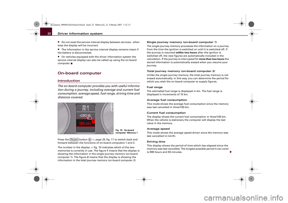
distance covered.Press the button ⇒page 23, fig. 11 to switch back and
forward between the functions of on-board computers 1 and 2.
The number in the display ⇒fig. 10 indicates which of the two
memories is currently in use. The figure 1 means that the display is
showing the information in the single journey memory (on-board
computer 1). The figure 2 means that the display is showing the
information in the total journey memory (on-board computer 2).Single journey memory (on-board computer 1)
The single journey memory processes the information on a journey
from the time the ignition is switched on until it is switched off. If
the journey is resumed within two hours after the ignition is
switched off, the new figures are automatically included in the
calculation. If the journey is interrupted for more than two hours the
stored information is automatically erased when you resume your
journey.
Total journey memory (on-board computer 2)
Unlike the single journey memory, the total journey memory is not
erased automatically. In this way, you can determine the period for
which you wish the on-board computer to supply figures.
Fuel range
The estimated fuel range is displayed in km. The fuel range is
displayed in increments of 10 km.
Average fuel consumption
This mode shows the average fuel consumption since the memory
was last cancelled in litres/100 km.
Current fuel consumption
The display shows the current fuel consumption in litres/100 km.
When the vehicle is stationary the computer will display the last
value in the memory.
Average speed
This mode shows the average speed driven since the memory was
last cancelled (in km/h).
Driving time
This display shows the period of time which has elapsed since the
memory was last cancelled. The longest possible period it can cover
is 999 hours and 59 minutes.
Fig. 10 On-board
computer: Memory 1
Reset
AB
document_0900452a816e6cc9.book Seite 22 Mittwoch, 21. Februar 2007 1:32 13
Page 25 of 210
Driver information system23
Controls
Safety
Driving tips
General maintenance
Self-help
Technical data Distance covered
This display shows the distance you have covered since the memory
was last cancelled. The longest possible distance which can be
recorded is 9999.9 km.
Note
•
The displays for fuel consumption (average and current
consumption), fuel range and speed are shown in metric units.
•
The information in the memory is cancelled if the battery is
disconnected.
Controls
The on-board computer is controlled by means of two
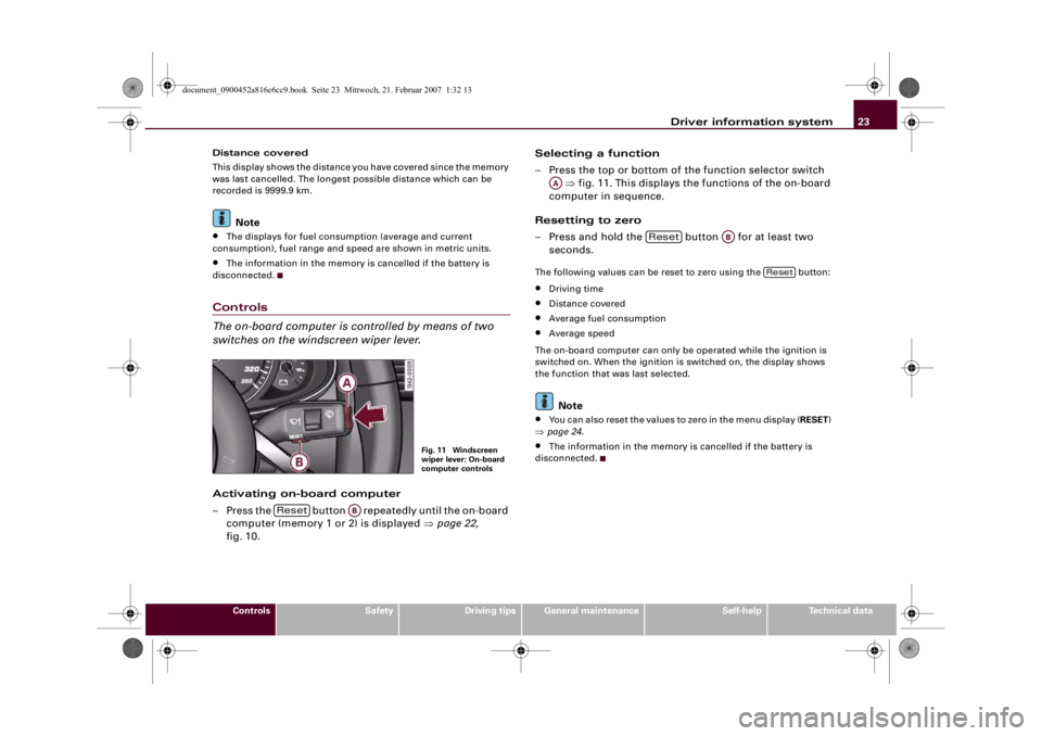
switches on the windscreen wiper lever.Activating on-board computer
– Press the button repeatedly until the on-board
computer (memory 1 or 2) is displayed ⇒page 22,
fig. 10.Selecting a function
– Press the top or bottom of the function selector switch
⇒fig. 11. This displays the functions of the on-board
computer in sequence.
Resetting to zero
– Press and hold the button for at least two
seconds.
The following values can be reset to zero using the button:•
Driving time
•
Distance covered
•
Average fuel consumption
•
Average speed
The on-board computer can only be operated while the ignition is
switched on. When the ignition is switched on, the display shows
the function that was last selected.Note
•
You can also reset the values to zero in the menu display (RESET)
⇒page 24.
•
The information in the memory is cancelled if the battery is
disconnected.
Fig. 11 Windscreen
wiper lever: On-board
computer controls
Reset
AB
AA
Reset
AB
Reset
document_0900452a816e6cc9.book Seite 23 Mittwoch, 21. Februar 2007 1:32 13
Page 36 of 210
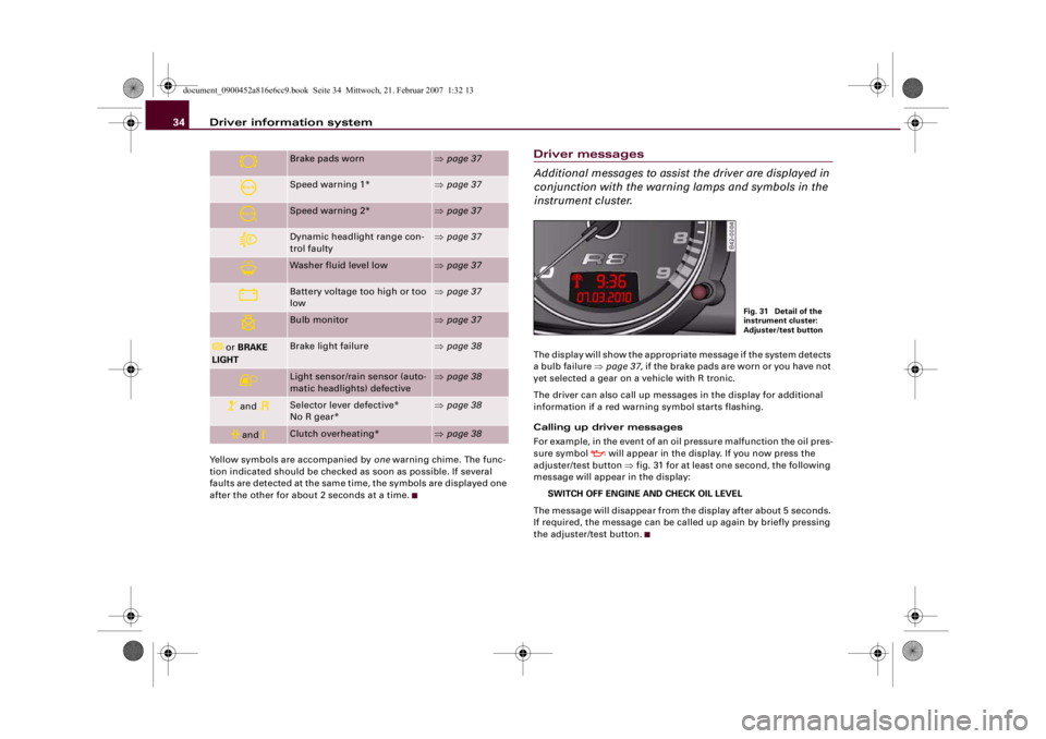
Driver information system 34Yellow symbols are accompanied by one warning chime. The func-
tion indicated should be checked as soon as possible. If several
faults are detected at the same time, the symbols are displayed one
after the other for about 2 seconds at a time.
Driver messages
Additional messages to assist the driver are displayed in
conjunction with the warning lamps and symbols in the
instrument cluster.The display will show the appropriate message if the system detects
a bulb failure ⇒page 37, if the brake pads are worn or you have not
yet selected a gear on a vehicle with R tronic.
The driver can also call up messages in the display for additional
information if a red warning symbol starts flashing.
Calling up driver messages
For example, in the event of an oil pressure malfunction the oil pres-
sure symbol
will appear in the display. If you now press the
adjuster/test button ⇒fig. 31 for at least one second, the following
message will appear in the display:
SWITCH OFF ENGINE AND CHECK OIL LEVEL
The message will disappear from the display after about 5 seconds.
If required, the message can be called up again by briefly pressing
the adjuster/test button.
Brake pads worn
⇒page 37
Speed warning 1*
⇒page 37
Speed warning 2*
⇒page 37
Dynamic headlight range con-
trol faulty
⇒page 37
Washer fluid level low
⇒page 37
Battery voltage too high or too
low
⇒page 37
Bulb monitor
⇒page 37
or BRAKE
LIGHT
Brake light failure
⇒page 38
Light sensor/rain sensor (auto-
matic headlights) defective
⇒page 38
and
Selector lever defective*
No R gear*
⇒page 38
and
Clutch overheating*
⇒page 38
Fig. 31 Detail of the
instrument cluster:
Adjuster/test button
document_0900452a816e6cc9.book Seite 34 Mittwoch, 21. Februar 2007 1:32 13
Page 39 of 210
Driver information system37
Controls
Safety
Driving tips
General maintenance
Self-help
Technical data
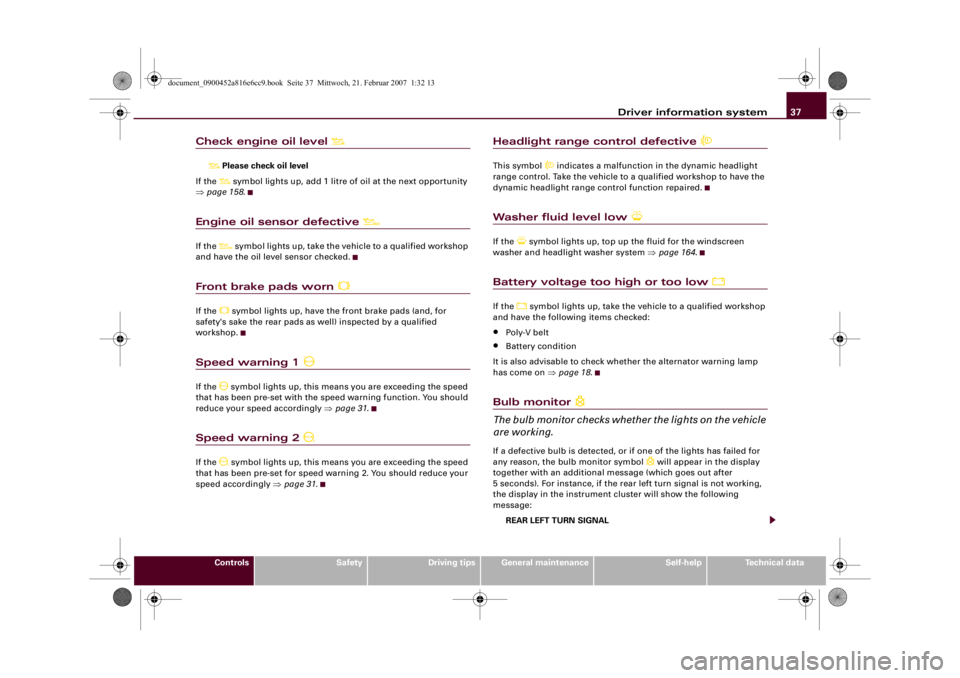
Check engine oil level
Please check oil level
If the symbol lights up, add 1 litre of oil at the next opportunity
⇒page 158.
Engine oil sensor defective
If the
symbol lights up, take the vehicle to a qualified workshop
and have the oil level sensor checked.
Front brake pads worn
If the
symbol lights up, have the front brake pads (and, for
safety's sake the rear pads as well) inspected by a qualified
workshop.
Speed warning 1
If the
symbol lights up, this means you are exceeding the speed
that has been pre-set with the speed warning function. You should
reduce your speed accordingly ⇒page 31.
Speed warning 2
If the
symbol lights up, this means you are exceeding the speed
that has been pre-set for speed warning 2. You should reduce your
speed accordingly ⇒page 31.
Headlight range control defective
This symbol
indicates a malfunction in the dynamic headlight
range control. Take the vehicle to a qualified workshop to have the
dynamic headlight range control function repaired.
Washer fluid level low
If the
symbol lights up, top up the fluid for the windscreen
washer and headlight washer system ⇒page 164.
Battery voltage too high or too low
If the
symbol lights up, take the vehicle to a qualified workshop
and have the following items checked:
•
Poly-V belt
•
Battery condition
It is also advisable to check whether the alternator warning lamp
has come on ⇒page 18.
Bulb monitor
The bulb monitor checks whether the lights on the vehicle
are working.If a defective bulb is detected, or if one of the lights has failed for
any reason, the bulb monitor symbol
will appear in the display
together with an additional message (which goes out after
5 seconds). For instance, if the rear left turn signal is not working,
the display in the instrument cluster will show the following
message:
REAR LEFT TURN SIGNAL
document_0900452a816e6cc9.book Seite 37 Mittwoch, 21. Februar 2007 1:32 13
Page 42 of 210
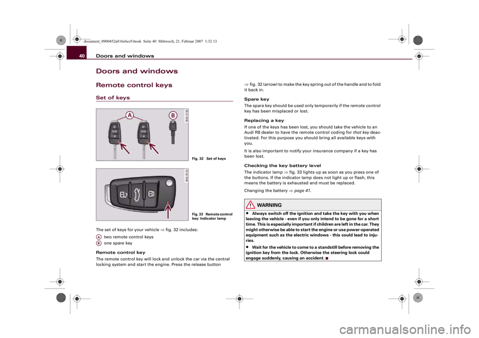
Doors and windows 40Doors and windowsRemote control keysSet of keysThe set of keys for your vehicle ⇒fig. 32 includes:
two remote control keys
one spare key
Remote control key
The remote control key will lock and unlock the car via the central
locking system and start the engine. Press the release button ⇒fig. 32 (arrow) to make the key spring out of the handle and to fold
it back in.
Spare key
The spare key should be used only temporarily if the remote control
key has been misplaced or lost.
Replacing a key
If one of the keys has been lost, you should take the vehicle to an
Audi R8 dealer to have the remote control coding for that key deac-
tivated. For this purpose you should bring all available keys with
you.
It is also important to notify your insurance company if a key has
been lost.
Checking the key battery level
The indicator lamp ⇒fig. 33 lights up as soon as you press one of
the buttons. If the indicator lamp does not light up or flash, this
means the battery is exhausted and must be replaced.
Changing the battery ⇒page 41.
WARNING
•
Always switch off the ignition and take the key with you when
leaving the vehicle - even if you only intend to be gone for a short
time. This is especially important if children are left in the car. They
might otherwise be able to start the engine or use power-operated
equipment such as the electric windows - this could lead to inju-
ries.
•
Wait for the vehicle to come to a standstill before removing the
ignition key from the lock. Otherwise the steering lock could
engage suddenly, causing an accident.
Fig. 32 Set of keysF i g . 3 3 R e m o t e c o n t r o l
key: Indicator lamp
AAAB
document_0900452a816e6cc9.book Seite 40 Mittwoch, 21. Februar 2007 1:32 13
Page 43 of 210
Doors and windows41
Controls
Safety
Driving tips
General maintenance
Self-help
Technical data
Remote control key
The remote control will lock and unlock the vehicle
without having to insert the key in the lock.The remote control transmitter and the battery are integrated in the
handle of the key. The receiver is in the interior of the vehicle. The
maximum range of the remote control depends on various factors.
The range is reduced when the battery starts to lose power.
If the receiver has been repaired or replaced, or if a replacement key
is used, the system will need re-programming by a qualified work-
shop. This is necessary so that the receiver can recognise your
remote control key.
The remote control keys (which are radio-operated) conform with all
relevant requirements for Germany and have been approved by the
Federal Approvals Office for Telecommunications of the Federal
Republic of Germany. All components are marked in accordance
with the current legal requirements. This certification forms the
basis for approval for use in other countries.
Personalised remote control key
When you switch off the ignition or lock the vehicle, the settings of
various convenience features are automatically stored and assigned
individually to the remote control key that is currently in use. The
settings stored for the remote control key are then recalled auto-
matically the next time the vehicle is unlocked, the door is opened
or the ignition is switched on.
Note
•
The remote control key is automatically deactivated when the
ignition is switched on.
•
The function of the remote control key may be impaired by inter-
ference from other nearby radio signals (for example from a mobile
telephone or TV transmitter) if these are in the same frequency
range.
Synchronisation
If the remote control fails to unlock the vehicle, it will be
necessary to re-synchronise the system.– Press the unlock button
on the remote control.
– Use the key to manually unlock the driver's door within
30 seconds.
– Press the unlock
or the lock button
.
Replacing the battery for the remote control key
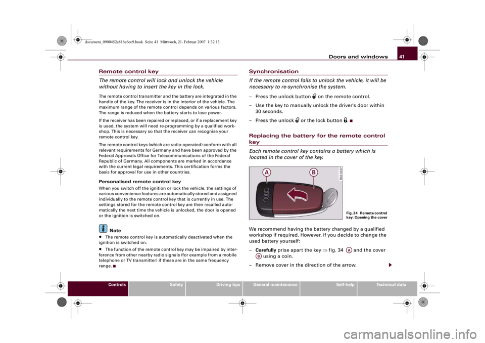
Each remote control key contains a battery which is
located in the cover of the key.We recommend having the battery changed by a qualified
workshop if required. However, if you decide to change the
used battery yourself:
–Carefully prise apart the key ⇒fig. 34 and the cover
using a coin.
– Remove cover in the direction of the arrow.
F i g . 3 4 R e m o t e c o n t r o l
key: Opening the coverAA
AB
document_0900452a816e6cc9.book Seite 41 Mittwoch, 21. Februar 2007 1:32 13