maintenance reset AUDI R8 2007 Owners Manual
[x] Cancel search | Manufacturer: AUDI, Model Year: 2007, Model line: R8, Model: AUDI R8 2007Pages: 210, PDF Size: 8.1 MB
Page 13 of 210

Instruments and warning/indicator lamps11
Controls
Safety
Driving tips
General maintenance
Self-help
Technical data
Rev counter
The rev counter indicates the number of engine revolu-
tions per minute.You should select a lower gear if the engine speed drops below
1500 rpm. The start of the red zone on the dial indicates the
maximum engine speed which may be used briefly when the engine
is warm and after it has been run in properly. However, it is advisable
to change up a gear or lift your foot off the accelerator (or shift out
of the R tronic sport mode) before the needle reaches the red zone.
Caution
Never allow the rev counter needle ⇒page 10, fig. 2 to go into
the red zone on the scale for more than a very brief period: there is
a risk of damaging the engine. The start of the red zone on the dial
is different for some engine versions.Radio-controlled clockWhen the clock is in “radio-control” mode the signal recep-
tion symbol (a radio tower with radio waves) appears in the
display ⇒fig. 3. It is then not possible to change the
minutes or the date manually. If you take your vehicle into a different time zone, the hour display will need to be
adjusted manually to local time using the adjuster button.
Setting the time zone
– Keep pulling the button ⇒fig. 3 briefly until the time
zone display flashes (select setting “0” if you do not wish
to change the time zone).
– Then turn the button to the left (to set an earlier time
zone: -1/-2) or to the right (to set a later time zone: +1/+2).
Switching date display on and off
– Keep pulling the button briefly until the date display
flashes.
– Then turn the button to the left or right.
When the display stops flashing, this means the setting you are
performing is completed and the time zone has been successfully
stored.
If the clock does not receive a radio signal for three consecutive
days, it will automatically switch to “quartz” mode. The signal recep-
tion symbol will then disappear. If you need to reset the time and
date, proceed as described on ⇒page 12.
A2
Fig. 3 Detail of the
instrument cluster:
Display with signal
reception symbol, time
and date
document_0900452a816e6cc9.book Seite 11 Mittwoch, 21. Februar 2007 1:32 13
Page 15 of 210
Instruments and warning/indicator lamps13
Controls
Safety
Driving tips
General maintenance
Self-help
Technical data Warning lamp
If the symbol
flashes in the display, this means that either the
coolant temperature is too high or the coolant level is too low
⇒page 35.
If the needle is over to the far right on the dial, this means the
coolant temperature is too high. Stop the vehicle, switch off the
engine and wait for it to cool down. If the warning lamp starts
flashing again after just a short distance, contact a qualified work-
shop.
WARNING
•
Before opening the engine lid and checking the coolant level,
please observe the warning information on ⇒page 155, “Working
on components in the engine compartment”.
•
Never open the engine lid if you can see or hear steam or
coolant escaping from the engine compartment; there is a risk of
being scalded. Wait until you can no longer see or hear escaping
steam or coolant.Caution
•
Additional lights and other accessories in front of the air inlet
reduce the cooling effect of the radiator. At high outside tempera-
tures and high engine loads, there is a risk of the engine over-
heating.
•
The front spoiler also ensures proper distribution of the cooling
air when the vehicle is moving. If the spoiler is damaged this can
reduce the cooling effect, which could cause the engine to overheat.
You should obtain professional assistance.
Fuel gaugeThe gauge only works when the ignition is switched on. When the
needle reaches the reserve zone, the symbol
lights up in the instrument cluster display ⇒page 36. At this point there are still
about 10 litres of fuel left in the tank. This is your reminder to fill up
soon.
The tank capacity of your vehicle is given in the Technical data
section ⇒page 198.
Caution
Never run the tank completely dry. If there is an irregular fuel supply,
misfiring can occur. This allows unburnt fuel to enter the exhaust
system, which could cause overheating and damage the catalytic
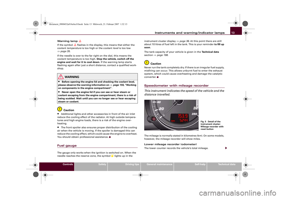
converter.Speedometer with mileage recorder
This instrument indicates the speed of the vehicle and the
distance travelled.The mileage is normally stated in kilometres (km). On some models,
however, the mileage recorder will show miles.
Lower mileage recorder (odometer)
The lower counter records the vehicle's total mileage.
Fig. 5 Detail of the
instrument cluster:
Mileage recorder with
reset button
document_0900452a816e6cc9.book Seite 13 Mittwoch, 21. Februar 2007 1:32 13
Page 23 of 210
Driver information system21
Controls
Safety
Driving tips
General maintenance
Self-help
Technical data
•
On vehicles equipped with the Audi navigation system* the
displays may vary from the normal lay-out during route guidance.
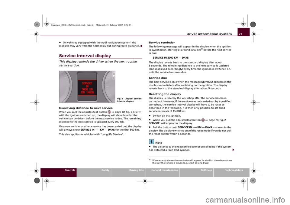
Service interval displayThis display reminds the driver when the next routine
service is due.Displaying distance to next service
When you pull the adjuster/test button ⇒page 10, fig. 2 briefly
with the ignition switched on, the display will show how far the
vehicle can be driven before the next service is due. The remaining
distance to the next service is updated every 500 km.
On a new vehicle, or after a service has been carried out, the display
will always show SERVICE IN ----- KM --- DAYS for the first 500 km.
This also applies to vehicles with “LongLife Service”.Service reminder
The following message will appear in the display when the ignition
is switched on, starting at around 2000 km
1) before the next service
is due:
SERVICE IN 2000 KM --- DAYS
The display reverts back to the standard display after about
5 seconds. The remaining distance to the next service is updated
(and displayed accordingly) every time the ignition is switched on,
until the service becomes due.
Service due
The next service is due when the message SERVICE! appears in the
display immediately after switching on the ignition. The display
reverts back to the standard display after about 5 seconds.
Resetting the display
The display is reset by the workshop after the service has been
carried out. However, if the service was not carried out by a qualified
workshop, the service interval display will have to be reset as
described in the following. It is then only possible to set fixed
service intervals of 15,000 km.
•
Switch on the ignition.
•
When you pull the adjuster/test button ⇒page 10, fig. 2
SERVICE! will appear in the display.
•
Pull the button until SERVICE IN ----- KM --- DAYS is shown in the
display. The display switches out of the reset mode if you do not pull
the reset button within 5 seconds.Note
•
The distance to the next service cannot be called up if the system
has detected a fault (red symbol).
Fig. 9 Display: Service
interval display
A10
1)When exactly the service reminder will appear for the first time depends on
the way the vehicle is driven (e.g. short or long trips).
A10
document_0900452a816e6cc9.book Seite 21 Mittwoch, 21. Februar 2007 1:32 13
Page 25 of 210
Driver information system23
Controls
Safety
Driving tips
General maintenance
Self-help
Technical data Distance covered
This display shows the distance you have covered since the memory
was last cancelled. The longest possible distance which can be
recorded is 9999.9 km.
Note
•
The displays for fuel consumption (average and current
consumption), fuel range and speed are shown in metric units.
•
The information in the memory is cancelled if the battery is
disconnected.
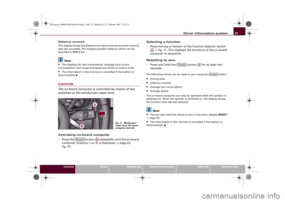
Controls
The on-board computer is controlled by means of two
switches on the windscreen wiper lever.Activating on-board computer
– Press the button repeatedly until the on-board
computer (memory 1 or 2) is displayed ⇒page 22,
fig. 10.Selecting a function
– Press the top or bottom of the function selector switch
⇒fig. 11. This displays the functions of the on-board
computer in sequence.
Resetting to zero
– Press and hold the button for at least two
seconds.
The following values can be reset to zero using the button:•
Driving time
•
Distance covered
•
Average fuel consumption
•
Average speed
The on-board computer can only be operated while the ignition is
switched on. When the ignition is switched on, the display shows
the function that was last selected.Note
•
You can also reset the values to zero in the menu display (RESET)
⇒page 24.
•
The information in the memory is cancelled if the battery is
disconnected.
Fig. 11 Windscreen
wiper lever: On-board
computer controls
Reset
AB
AA
Reset
AB
Reset
document_0900452a816e6cc9.book Seite 23 Mittwoch, 21. Februar 2007 1:32 13
Page 27 of 210
Driver information system25
Controls
Safety
Driving tips
General maintenance
Self-help
Technical data
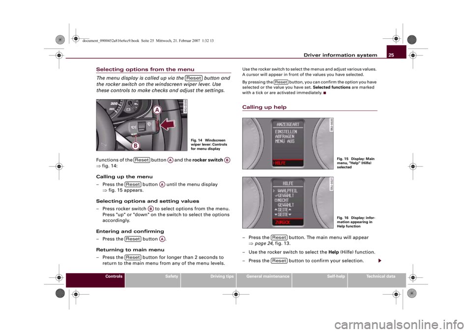
Selecting options from the menu
The menu display is called up via the button and
the rocker switch on the windscreen wiper lever. Use
these controls to make checks and adjust the settings.Functions of the button and the rocker switch
⇒fig. 14:
Calling up the menu
– Press the button until the menu display
⇒fig. 15 appears.
Selecting options and setting values
– Press rocker switch to select options from the menu.
Press "up" or "down" on the switch to select the options
accordingly.
Entering and confirming
– Press the button .
Returning to main menu
– Press the button for longer than 2 seconds to
return to the main menu from any of the menu levels.
Use the rocker switch to select the menus and adjust various values.
A cursor will appear in front of the values you have selected.
By pressing the button, you can confirm the option you have
selected or the value you have set. Selected functions are marked
with a tick or are activated immediately.Calling up help– Press the button. The main menu will appear
⇒page 24, fig. 13.
– Use the rocker switch to select the Help (Hilfe) function.
– Press the button to confirm your selection.
ResetFig. 14 Windscreen
wiper lever: Controls
for menu display
Reset
AA
AB
Reset
AA
AB
Reset
AA
Reset
Reset
Fig. 15 Display: Main
menu, "Help" (Hilfe)
selectedFig. 16 Display: infor-
mation appearing in
Help function
ResetReset
document_0900452a816e6cc9.book Seite 25 Mittwoch, 21. Februar 2007 1:32 13
Page 29 of 210
Driver information system27
Controls
Safety
Driving tips
General maintenance
Self-help
Technical data
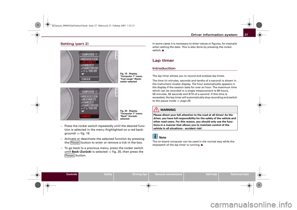
Setting (part 2)– Press the rocker switch repeatedly until the desired func-
tion is selected in the menu (highlighted on a red back-
ground) ⇒fig. 19.
– Activate or deactivate the selected function by pressing
the button to enter or remove a tick in the box.
– To go back to a previous menu, press the rocker switch
until Back (Zurück) is selected ⇒fig. 20, then press the
button.
In some cases it is necessary to enter values or figures, for example
when setting the date. This is also done by pressing the rocker
switch.Lap timerIntroductionThe lap timer allows you to record and analyse lap times.
The time (in minutes, seconds and tenths of a second) is shown in
the instrument cluster display. The hour automatically appears in
the display if the session lasts for over an hour. The maximum time
which can be recorded in a single measurement is 99 hours,
59 minutes, 59 seconds and 9/10 of a second. If this time is
exceeded, the lap timer will automatically stop recording and switch
to the pause mode ⇒page 29.
WARNING
Please direct your full attention to the road at all times! As the
driver, you have full responsibility for the safety of the vehicle and
other road users. For this reason, you should only use the func-
tions in a manner that allows you to maintain control of the
vehicle in all situations - accident risk!
Note
The on-board computer can be used in the normal way while the
stopwatch of the lap timer is running.
Fig. 19 Display:
"Computer 1" menu,
"Fuel range" (Reich-
weite) selectedFig. 20 Display:
"Computer 1" menu,
"Back" (Zurück)
selected
Reset
Reset
document_0900452a816e6cc9.book Seite 27 Mittwoch, 21. Februar 2007 1:32 13
Page 33 of 210
Driver information system31
Controls
Safety
Driving tips
General maintenance
Self-help
Technical data
Resuming the lap time session laterWhen you have evaluated the lap times, you can resume the
session and continue recording lap times later.
– Keep pressing the button until the lap timer
appears ⇒page 30, fig. 27.
– Press the top part of the rocker switch to start recording
a new lap time.
– To record further lap times, repeat the procedure
described earlier ⇒page 29, “Recording further lap
times”. To evaluate the overall results, refer to ⇒page 30,
“Finishing the session and evaluating or resetting lap
times”.Speed warning functionApplies to vehicles: with speed warning functionIntroduction
The speed warning function can help you keep below a
pre-set maximum speed.
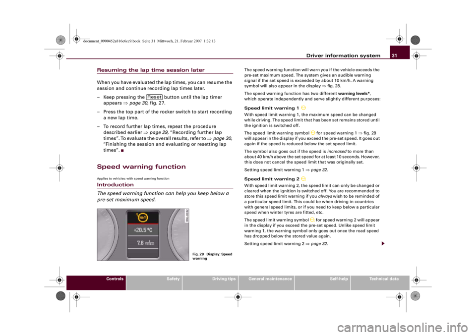
The speed warning function will warn you if the vehicle exceeds the
pre-set maximum speed. The system gives an audible warning
signal if the set speed is exceeded by about 10 km/h. A warning
symbol will also appear in the display ⇒fig. 28.
The speed warning function has two different warning levels*,
which operate independently and serve slightly different purposes:
Speed limit warning 1
With speed limit warning 1, the maximum speed can be changed
while driving. The speed limit that has been set remains stored until
the ignition is switched off.
The speed limit warning symbol
for speed warning 1 ⇒fig. 28
will appear in the display if you exceed the pre-set speed. It goes out
again if the speed is reduced below the set speed limit.
The symbol also goes out if the speed is increased to more than
about 40 km/h above the set speed for at least 10 seconds. However,
this does not cancel the speed limit that was originally set.
Setting speed limit warning 1 ⇒page 32.
Speed limit warning 2
With speed limit warning 2, the speed limit can only be changed or
cleared when the ignition is switched off. You are recommended to
store this speed limit warning if you always wish to be reminded of
a particular speed limit. This could be when driving in countries
with general speed limits, or if you need to keep below a particular
speed when winter tyres are fitted, etc.
The speed limit warning symbol
for speed warning 2 will appear
in the display if you exceed the pre-set speed. Unlike speed limit
warning 1, the warning symbol only goes out once the road speed
has dropped below the stored value again.
Setting speed limit warning 2 ⇒page 32.
Reset
Fig. 28 Display: Speed
warning
document_0900452a816e6cc9.book Seite 31 Mittwoch, 21. Februar 2007 1:32 13
Page 35 of 210
Driver information system33
Controls
Safety
Driving tips
General maintenance
Self-help
Technical data
Clearing speed limit
– Switch off the ignition.
– Briefly press the adjuster/test button in the instrument
cluster ⇒page 32, fig. 29. The mileage recorder display
and the digital clock will light up.
– Press the adjuster/test button for at least 2 seconds. The
display will show the speed limit which is currently set.
– Now press and hold the button on the wind-
screen wiper lever ⇒page 32, fig. 30 until the
crossed-out warning symbol for speed limit 2 appears on
the display.The display lighting for the mileage recorder and digital clock goes
off again a few seconds after the button is released.
Note
This speed limit function can also be operated via the on-board
computer ⇒page 25, “Selecting options from the menu”.Notes and symbolsRed symbols
A red symbol warns of a serious malfunction.–Stop the vehicle.
– Switch off the engine.
– Check the function displayed. Obtain professional assist-
ance if necessary.
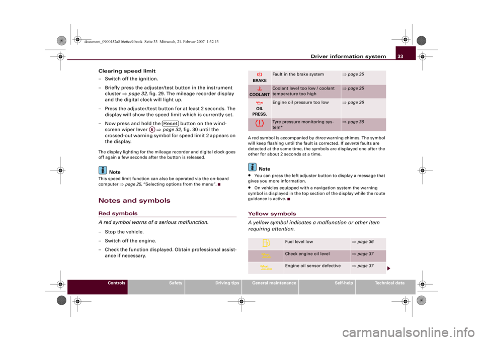
A red symbol is accompanied by three warning chimes. The symbol
will keep flashing until the fault is corrected. If several faults are
detected at the same time, the symbols are displayed one after the
other for about 2 seconds at a time.
Note
•
You can press the left adjuster button to display a message that
gives you more information.
•
On vehicles equipped with a navigation system the warning
symbol is displayed in the top section of the display while the route
guidance is active.
Yellow symbols
A yellow symbol indicates a malfunction or other item
requiring attention.
Reset
AB
BRAKE
Fault in the brake system
⇒page 35
COOLANT
Coolant level too low / coolant
temperature too high
⇒page 35
OIL
PRESS.
Engine oil pressure too low
⇒page 36
Tyre pressure monitoring sys-
tem*
⇒page 36
Fuel level low
⇒page 36
Check engine oil level
⇒page 37
Engine oil sensor defective
⇒page 37
document_0900452a816e6cc9.book Seite 33 Mittwoch, 21. Februar 2007 1:32 13
Page 55 of 210
Lights and vision53
Controls
Safety
Driving tips
General maintenance
Self-help
Technical data
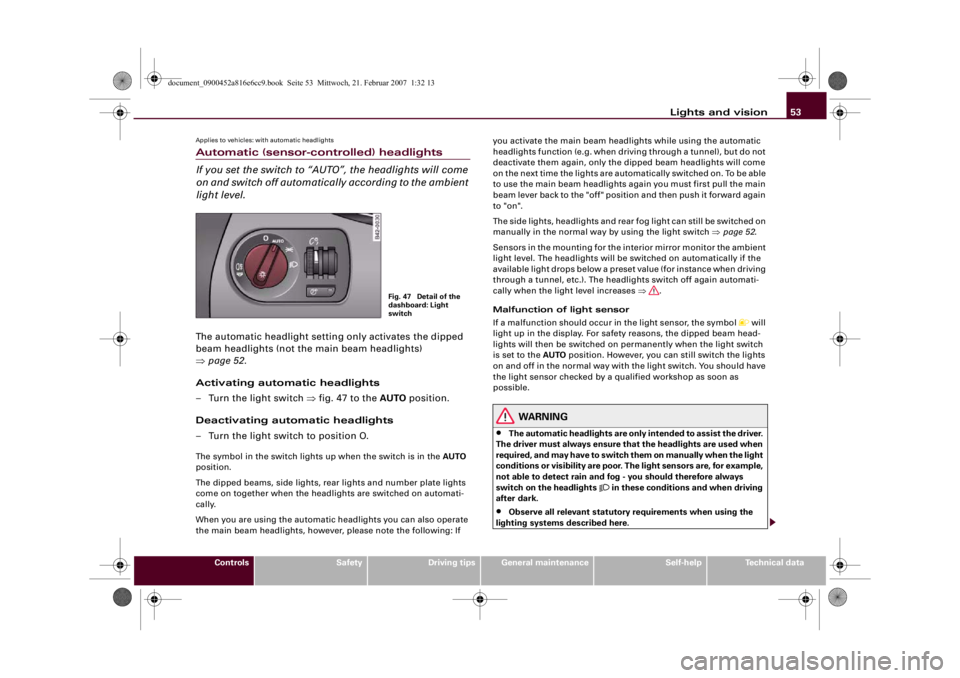
Applies to vehicles: with automatic headlightsAutomatic (sensor-controlled) headlights
If you set the switch to “AUTO”, the headlights will come
on and switch off automatically according to the ambient
light level.The automatic headlight setting only activates the dipped
beam headlights (not the main beam headlights)
⇒page 52.
Activating automatic headlights
– Turn the light switch ⇒fig. 47 to the AUTO position.
Deactivating automatic headlights
– Turn the light switch to position O.The symbol in the switch lights up when the switch is in the AUTO
position.
The dipped beams, side lights, rear lights and number plate lights
come on together when the headlights are switched on automati-
cally.
When you are using the automatic headlights you can also operate
the main beam headlights, however, please note the following: If you activate the main beam headlights while using the automatic
headlights function (e.g. when driving through a tunnel), but do not
deactivate them again, only the dipped beam headlights will come
on the next time the lights are automatically switched on. To be able
to use the main beam headlights again you must first pull the main
beam lever back to the "off" position and then push it forward again
to "on".
The side lights, headlights and rear fog light can still be switched on
manually in the normal way by using the light switch ⇒page 52.
Sensors in the mounting for the interior mirror monitor the ambient
light level. The headlights will be switched on automatically if the
available light drops below a preset value (for instance when driving
through a tunnel, etc.). The headlights switch off again automati-
cally when the light level increases ⇒.
Malfunction of light sensor
If a malfunction should occur in the light sensor, the symbol
will
light up in the display. For safety reasons, the dipped beam head-
lights will then be switched on permanently when the light switch
is set to the AUTO position. However, you can still switch the lights
on and off in the normal way with the light switch. You should have
the light sensor checked by a qualified workshop as soon as
possible.
WARNING
•
The automatic headlights are only intended to assist the driver.
The driver must always ensure that the headlights are used when
required, and may have to switch them on manually when the light
conditions or visibility are poor. The light sensors are, for example,
not able to detect rain and fog - you should therefore always
switch on the headlights
in these conditions and when driving
after dark.
•
Observe all relevant statutory requirements when using the
lighting systems described here.
Fig. 47 Detail of the
dashboard: Light
switch
document_0900452a816e6cc9.book Seite 53 Mittwoch, 21. Februar 2007 1:32 13
Page 63 of 210
Lights and vision61
Controls
Safety
Driving tips
General maintenance
Self-help
Technical data
Service position
The wiper blades can only be replaced when the wiper
arms are in the service position.The windscreen wipers will only function if the luggage lid
is completely closed.
Moving the wiper blades into the service
position
– In icy conditions, check that the wiper blades are not
frozen to the windscreen.
– Switch on the ignition.
– Move the windscreen wiper lever to position 0.
– Press the button repeatedly until the DISPLAY
TYPE menu appears in the driver information system
display.
– Use the rocker switch and the button to select
SET > WIPERS > FRONT > SERVICE POSITION ON. The
wiper arms will move into the service position.Returning the wiper blades to their normal park
position
– Make sure that the wiper blades are resting on the wind-
screen.
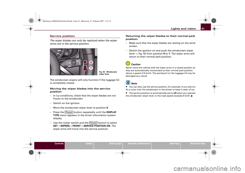
– Switch the ignition on and push the windscreen wiper
lever ⇒fig. 55 from position 0 to 1. The wiper arms will
return to their normal park position.
Caution
Never move the vehicle with the wiper arms in a raised position as
they are automatically moved back to their normal park position
above a speed of 6 km/h. The paintwork on the luggage lid may be
damaged as a result.
Note
•
You can also use the service position, for example, if you want to
fix a cover over the windscreen in the winter to keep it clear of ice.
•
The service position is automatically set to off when you operate
the windscreen wiper lever or the road speed exceeds 6 km/h.
Fig. 55 Windscreen
wiper lever
Reset
Reset
document_0900452a816e6cc9.book Seite 61 Mittwoch, 21. Februar 2007 1:32 13