length AUDI R8 SPYDER 2011 Owners Manual
[x] Cancel search | Manufacturer: AUDI, Model Year: 2011, Model line: R8 SPYDER, Model: AUDI R8 SPYDER 2011Pages: 244, PDF Size: 59.74 MB
Page 25 of 244
Average fuel mileage
The average fuel economy in MPG (l/ 100 km)
since you last clea red the memory appears in
this display .
Current fuel mileage
The instantaneous fue l consumption in miles
per gallo n (l/100 km) is shown in this d isp lay.
W hen the ve hicle is stationary, t he most re
cent fuel consumption is displayed.
Average speed
The average speed in mph (km/h) since the
l ast time the disp lay was reset appears i n the
d isp lay.
Elapsed t ime
T he length of time that you have been driving
since you last reset the memory appears in
this display . T he maximum time period that
can be recorded is 999 hours and 59 minutes .
Distance
The elapsed distance since the la st time the
memory was clea red appears i n the display .
The max imum d istance that can be recorded
i s 9,999 .9 m iles (9 ,999 .9 kilometers) .
(D Tips
All stored values will be lost if the vehicle
battery is disconnected .
Operation
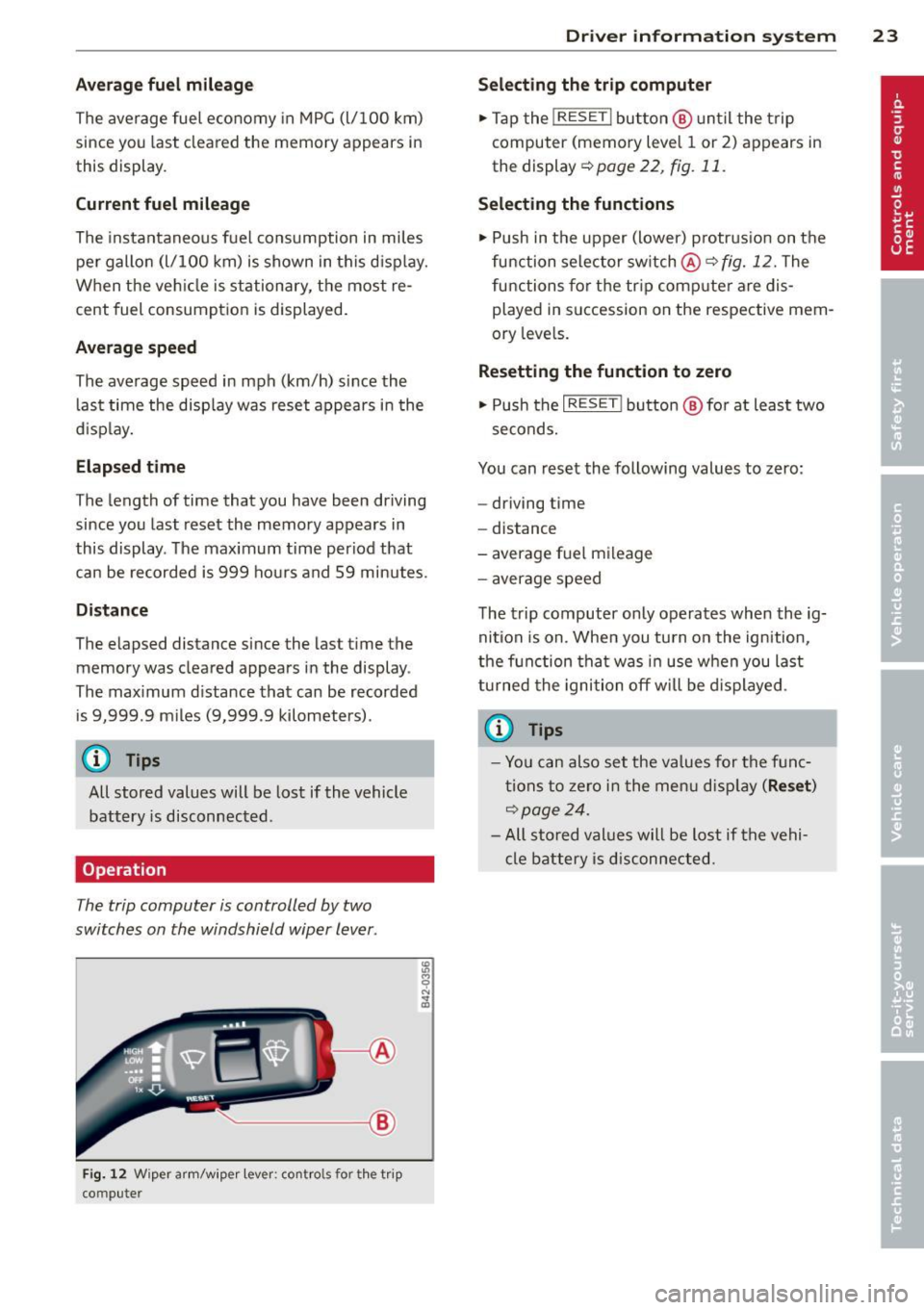
The trip computer is controlled by two
switches on the windshield wiper lever .
~---1@
Fig. 12 W iper a rm/w iper lev er: co ntro ls fo r the t rip
co mpute r
Dr iver in formation system 23
Selecting the trip computer
.,. Tap the !RESE T I button @ until the t rip
computer (memory leve l 1 or 2) ap pears in
the display ~poge22 ,
fig.11.
Selecting the functions
.,. Push in the upper (lower) p rotrus io n on t he
function selector sw itch
@ ~fig. 12. The
functions for t he tr ip comp ute r are dis
played in succession on the respective mem
ory leve ls.
Resetting the funct ion to zero
.,. Push the I RESE T! button @ for at leas t two
seconds.
You can reset the following values to zero:
- driving t ime
- distance
- average fue l m ileage
- a ver age speed
The trip computer only operates when the ig
nit ion is on . When you tu rn o n the ignition,
the f unction tha t was in use when you last
tu rned the ignition off will be displayed .
@ Tips
-Yo u can also set the va lues for the f unc
ti ons to ze ro i n t he me nu dis pl ay
(Re set )
~page 24.
-All sto red values will be lost if the vehi
cle battery i s disc onnected.
Page 31 of 244
each other and that have somewhat different purposes:
Speed warning 1 [i;[i ( Canada models )
You can use speed warning 1 to set the maxi
mum speed wh ile you are driv ing . T his se tting
will remain in effect until you t urn off the igni
tion, assuming that you have not changed or reset the setting .
The speed warning symbo l
[&1/lDl (Ca nada
models) in the warn ing 1 display appea rs
when you exceed the maximum speed. It goes
out when the speed falls be low the stored
maximum speed.
The speed warning symbo l wi ll also go out if
the speed
exceeds the stored maximum speed
by more than about 25 mph (40 km/h) for at
least 10 seconds. The stored maximum speed
is deleted .
Setting speed warning 1
r=;, page 29 .
Speed warning 2 EDJ/[al (Canada models )
Storing warning 2 is recommended if you al
ways
want to be reminded of a certa in speed,
for example when yo u are traveling in a coun
try that has a general maximum speed limit,
or if you do not want to exceed a spec ified
speed for winter tires.
The speed warning 2 symbol,
[il 1ra1 (Can ada
models) appears in the display when you ex
ceed the stored speed limit . Unlike warning 1,
it will not go out until the vehicle speed drops
be low the stored speed limit.
Sett ing speed warning 2
r=;, page 29.
(1') Tips
Even though you r vehicle is equipped with
a speed warning sys tem, you should s till
watch the speedometer to make sure you
are not driving faster than the speed limit.
Dr iver in formation system 29
Speed warning 1: setting a speed limit
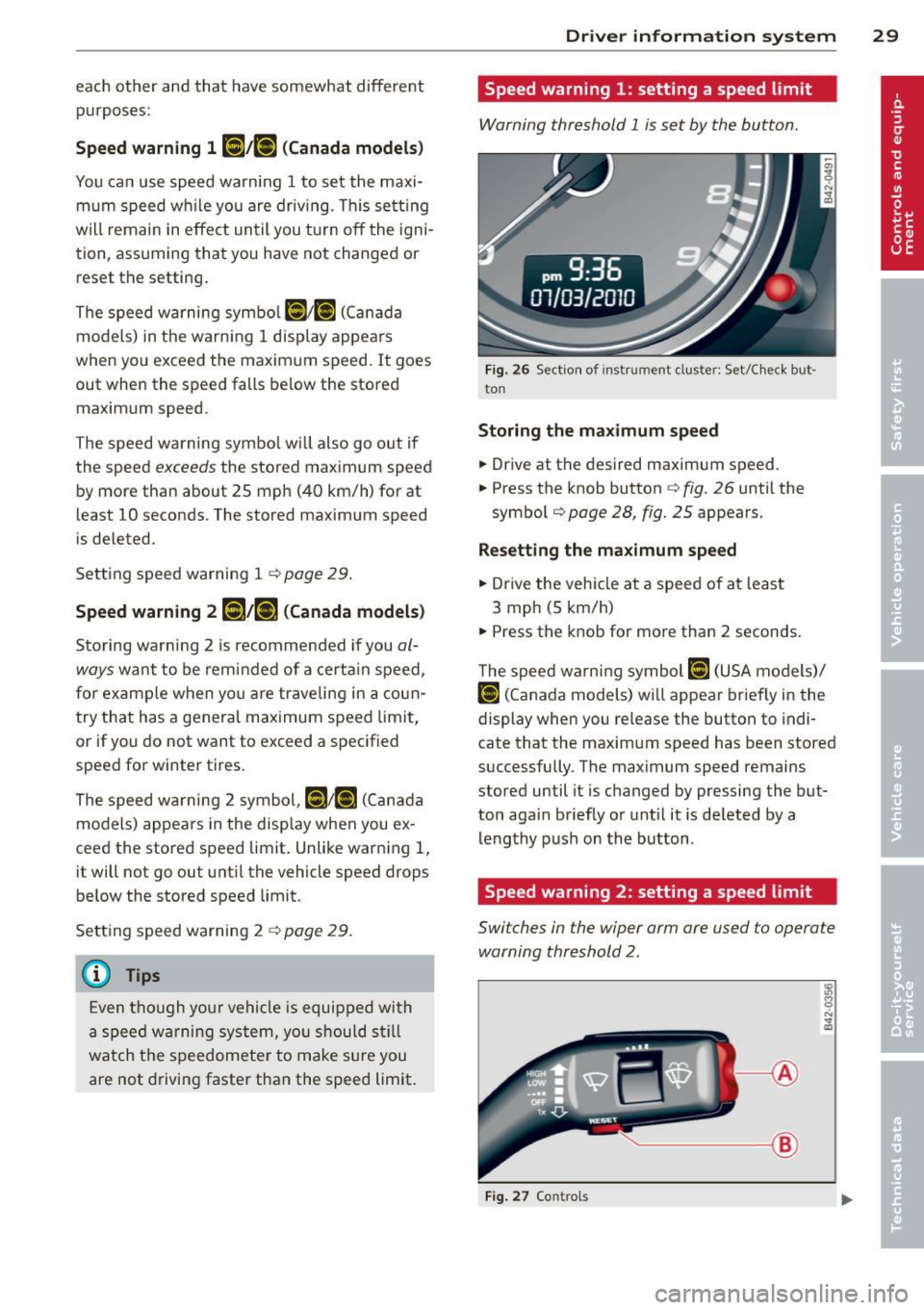
Warning threshold 1 is set by the button.
Fig. 26 Sect ion of instrument cluster: Set/Check but ·
ton
Storing the ma ximum spee d
.,. Drive at the desired maximum speed.
.,. Press the knob button
c::> fig. 26 until the
symbol
r=;, page 28, fig. 25 appears.
Resett ing th e ma ximum sp eed
.,. Dr ive the veh icle at a speed of at least
3 mph (5 km/h)
.,. Press the knob for more than 2 seconds.
T he speed warn ing symbol
lllH (USA models)/
Hll
cate that the maximum speed has been stored
successfully. The maximum speed remains
stored until it is changed by pressing the but
ton again briefly or unt il it is deleted by a
lengthy push on the button .
Speed warning 2: setting a speed limit
Switches in the wiper arm are used to operate
warning threshold
2.
'----1 @
Fig. 27 Controls
Page 58 of 244
56 Clear vision
shown as active in the driver information
system.
The
coming home function illuminates the
area around the vehicle when the ignition is
switched off and the driver's door is opened.
The length of time the lights remain on can be
set in the menu display
(Lights> Exterior
lights> coming home) .
The leaving home function illuminates the
area around the vehicle when unlocking it.
.&_ WARNING
- Never use daytime running lights to see
where you are going. They are not bright enough and will not let you see far
enough ahead for safety, especially at dusk or when it is dark. Be aware of
changes in outside light conditions when
you are driving and respond by switching
on your low beams.
- Automatic head- and taillight control is
only intended to assist the driver. This
feature does not relieve the driver of his
responsibility to check the headlights
and to turn them on manually according
to the current light and visibility condi
tions. For example, fog and rain cannot be detected by the light sensors. Conse
quently, always switch the headlights on
under these weather conditions and
when driving in the dark.
- Crashes can happen when you cannot see
the road ahead and when you cannot be
seen by other motorists.
-Always turn on the headlights so that you can see ahead and so that others can see your car from the back.
(D Tips
- Always observe the specific local regula
tions for your area when to use your
lights .
- Turn on low beams as evening ap
proaches or in conditions of poor visibili
ty.
- Do not attach stickers to the windshield
in front of the sensors as this can disable the automatic head- and
taillight control
and the automatic glare-dimming of the
rearview mirror(s)*.
- If you
remove the ignition from the igni
tion lock while the headlights are still
on, a buzzer will sound as long as the
driver's door is open to remind you to
turn off the lights.
- In the AUTO mode, the low beams are
turned off when the ignition is turned
off. The remaining lights are turned off
when the key is taken out of the ignition .
- In cool or damp weather conditions the
headlights may fog
over temporarily on
the inside.
- The critical factor is the temperature
difference between the interior and the
exterior of the headlight lens.
- With the main beams switched on, the
light-emitting area will be free of con
densation after a short time, however
the edges of the glass may still be fog
ged.
- This physical phenomenon has no ef
fect on the life of your vehicle's light
ing system.
Instrument panel illumination
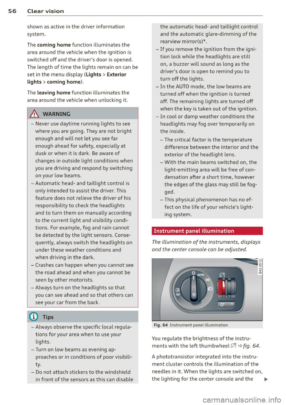
The illumination of the instruments, displays
and the center console can be adjusted.
Fig. 64 Instrument panel illumination
You regulate the brightness of the instru
ments with the left thumbwheel
(-'1· ~ fig. 64.
A phototransistor integrated into the instru
ment cluster controls the illumination of the
needles in it. When the lights are switched on,
the lighting for the center console and the
llll>
Page 64 of 244
62 Clear vis ion
Install ing th e wiper blade
.,. Pla ce the rounded end of the wiper onto the
end of the w iper arm in the
op pos ite direc
tion to the arrow @
r=;, fig. 71.
.,. Squeeze the corrugation on the w iper until
you hear it click in the wiper arm .
.,. Fold the wiper arm back onto the wind
shield .
.,. Switch the ign ition on and move the wiper
lever down briefly
r=;, page 59, fig . 69 . The
wipe r will move back to the park position.
_& WARNING
- Clean yo ur wiper blades regularly w it h a
windshield washer solution to prevent streaking. If the wipe r blades are very
dirty, for examp le with insects, carefu lly
clean the w iper blades with a sponge or a
soft brush.
- For your safety, you should replace the
wiper blades once or twice a year. See
your authorized Aud i dealer for replace
ment blades.
(D Note
- The w iper blades may only be changed
r=;, page 61 in the service position! Other
wise, you r isk damaging the paint on the
front lid o r the windsh ield wiper motor .
- To prevent damage to the wiper system:
-Always loose n blades which a re fro zen
t o the windshield before operating
w ipers.
- Do not use gasoline, kerosene, paint
t hinne r, or o ther solven ts on o r near
t he wipe r blades .
- Do not attemp t to move the wipers by
hand.
{D) Tips
The front wiper b lades are different
lengths; the blade o n the dr ive r's side is
longer .
Mirrors
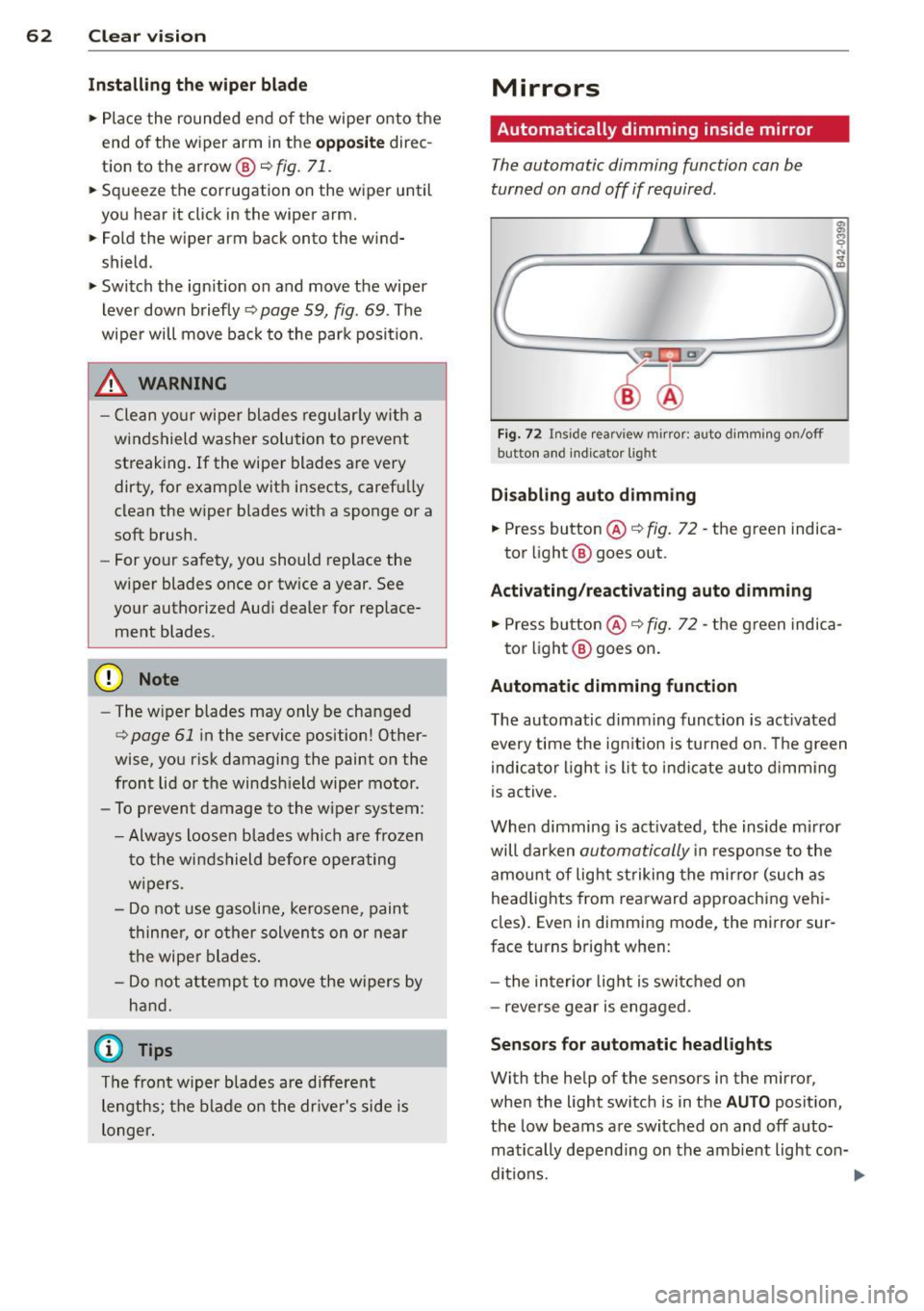
Automatically dimming inside mirror
The automatic dimming function can be
turned on and off if required .
Fig . 72 Inside rearv iew mirror: auto d imming on/off
button and ind icator lig ht
Disabling auto d imming
.,. Press button ® r=;, fig. 72 -the green indica
tor light @ goes out .
Activating /reactivating auto dimming
.,. Press button @¢ fig. 72 -the green indica-
tor light @ goes on .
Automatic dimming function
The automatic dimming function is act ivated
every time the ign it ion is turned on . T he g reen
indica tor light is lit to indicate auto d imming
is active.
When dimming is act ivated, the inside m irror
will darken
automatically i n response to the
amount of light st riking the mirro r (such as
headlig hts from rearward approaching vehi
cles). Even in dimming mode, the mirror sur
face turns bright when:
- t he in terior lig ht is swi tched on
- reverse gear is engaged.
Senso rs for automatic headlight s
With the help of the sensors in the mirror,
when the light switc h is in the
AUTO posit ion,
the low beams are switched on and off auto matically depending on the amb ient light con-
ditions. ..,.
Page 162 of 244
160 Driving and en vi ro nment
recommendations in your Warranty &
Maintenance booklet . Lack of proper
maintenance as well as improper use of
the veh icle w ill impair the funct ion of
the emission control system and could
l ead to damage.
- Do not alter or remove any component of
the Em ission Contro l System unless ap
proved by the manufacturer.
- Do not alter or remove any device, such
as heat shields, switches, ignition wires,
valves, wh ich are designed to protect
you r vehicle's Emiss ion Control System
and othe r important veh icle compo
nen ts.
(D Tips
The consumpt ion estimates as publish ed
by the ENVIRONM EN TAL PRO TECTIO N
AG ENCY ( EPA) and Transpor t Canada may
no t correspond to yo ur actua l cons ump
tion on the road, which will vary depend
ing upon vehicle load and speed, road and
weather conditions, trip length, etc.
Trailer towing
Your Audi RB is not designed to tow a trailer.
Towing a trai le r with yo ur Audi R8 is not rec
ommended and ca n cause damage to the vehi
cle . Damage caused by towing a tra iler is not
covered under warranty .
Page 207 of 244
the wheel bolts. These are available from au
thorized Audi dealers.
A WARNING
Using the wrong snow chains for your vehi
cle or installing them incorrectly can in
crease the risk of loss of control leading to
serious personal injury.
- Snow chains are available in different
sizes. Always make sure to follow the in
structions provided by the snow chain
manufacturer .
- When driving with snow chains, never
drive faster than the speed permitted for
your specific snow chains.
- Always observe local regulations.
- Remove snow chains before driving on
roads not covered with snow to avoid
damaging tires and wearing the snow
chains down unnecessarily.
- Snow chains, which come into direct con
tact with the wheel rim, can scratch or
damage it. Therefore, make sure that the
snow chains are suitably covered . Check
the position of the snow chains after
driving a few yards and correct if neces
sary. Follow the instructions from the
snow chain manufacturer when doing so.
(D Tips
Where snow chains are mandatory oncer
tain roads, this normally also applies to ve
hicles with all-wheel drive.
Wheel bolts
Wheel bolts must always be tightened to the
correct torque.
The design of wheel bolts is matched to the
factory installed rims. If different rims are fit
ted, the correct wheel bolts with the right
length and correctly shaped bolt heads must
be used. This ensures that wheels are fitted
securely and that the brake system functions
correctly .
Tires and wheels 205
In certain circumstances, you may not use
wheel bolts from a different vehicle -even if it
is the same model
r:!> page 211.
A WARNING
Improperly tightened or maintained wheel
bolts can become loose causing loss of
control, a collision and serious personal in
jury.
- Always keep the wheel bolts and the
threads in the wheel hubs clean so the
wheel bolts can turn easily and be prop erly tightened.
- Never grease or oil the wheel bolts and
the threads in the wheel hubs. They can
become loose while driving if greased or
oiled, even if tightened to the specified
torque.
- Only use wheel bolts that belong to the
rim being installed.
- Never use different wheels bolts on your
vehicle.
-Always maintain the correct tightening
torque for the wheel bolts to reduce the
risk of a wheel loss. If the tightening tor
que of the wheel bolts is too low, they
can loosen and come out when the vehi
cle is moving.
If the tightening torque is
too high, the wheel bolts and threads
can be damaged and the wheel can be
come loose.
(D Note
The specified torque for the wheel bolts is
90 ft lb (120 Nm) with a tolerance of ± 7 .4
ft lb( ± 10 Nm). Torque wheel bolts diago
nally. After changing a wheel, the torque
must be checked as soon as possible with a
torque wrench -preferably by an author
ized Audi dealer or qualified workshop.
Low aspect ratio tires
Your Audi is factory-equipped with low aspect
ratio tires. These tires have been thoroughly
tested and been selected specifically for your model for their superb performance, road feel
and handling under a variety of driving
IJ>,
•
•
Page 231 of 244
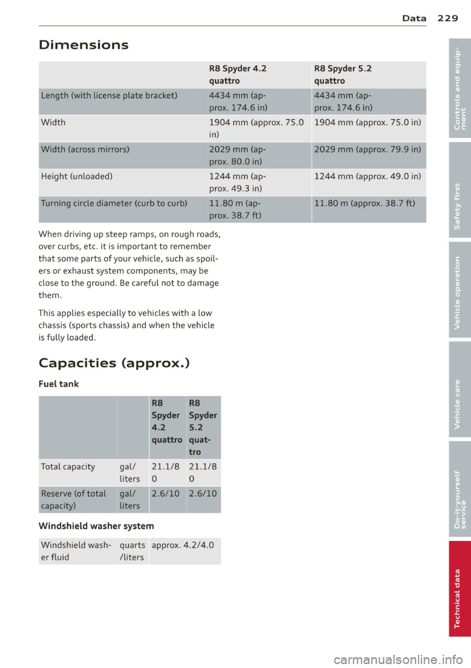
Dimensions
!Length (with license plate bracket)
Width
Width (across mirrors)
Height (unloaded)
T urning circle diameter (curb to curb) R8 Sp
yd er 4. 2
quattro
4434 mm (ap prox. 174.6 in)
1904 mm (approx . 75 .0
in)
2029 mm (ap prox. 80.0 in)
1244 mm (ap
prox. 49.3 in)
11.80
m (ap
prox. 3 8. 7
ft)
When driving up steep ramps, on rough roads,
over curbs, etc. it is important to remembe r
that some parts of your vehicle, such as spoil
ers or exhaust system components, may be
close to the ground . Be careful not to damage
them.
This applies especially to vehicles with a low chassis (sports chassis) and when the vehicle
is fully loaded .
Capacities (approx.)
Fuel tank
R8 R8
Spyder Spyder
4 .2 5.2
quattro quat -
tro
Total capacity gal/ 21.1/8 21.1/8
liters 0 0
Reserve (of total gal/ 2.6/10 2 .6/10
capacity) liters
Windshield wa she r sys tem
Windsh ield wash- quarts approx. 4.2/4.0
er fluid /liters
D ata 229
R8 Spyder 5.2
qu attro
4434 mm (ap prox. 174.6 in)
1904 mm (approx. 75.0 in)
2029 mm (approx. 79.9 in)
1
1244 mm (approx. 49.0 in)
11.80 m (approx. 38. 7
ft)
•
•