ECO mode AUDI R8 SPYDER 2012 User Guide
[x] Cancel search | Manufacturer: AUDI, Model Year: 2012, Model line: R8 SPYDER, Model: AUDI R8 SPYDER 2012Pages: 236, PDF Size: 59.24 MB
Page 24 of 236
22 Driver in formation sy ste m
Service interval display
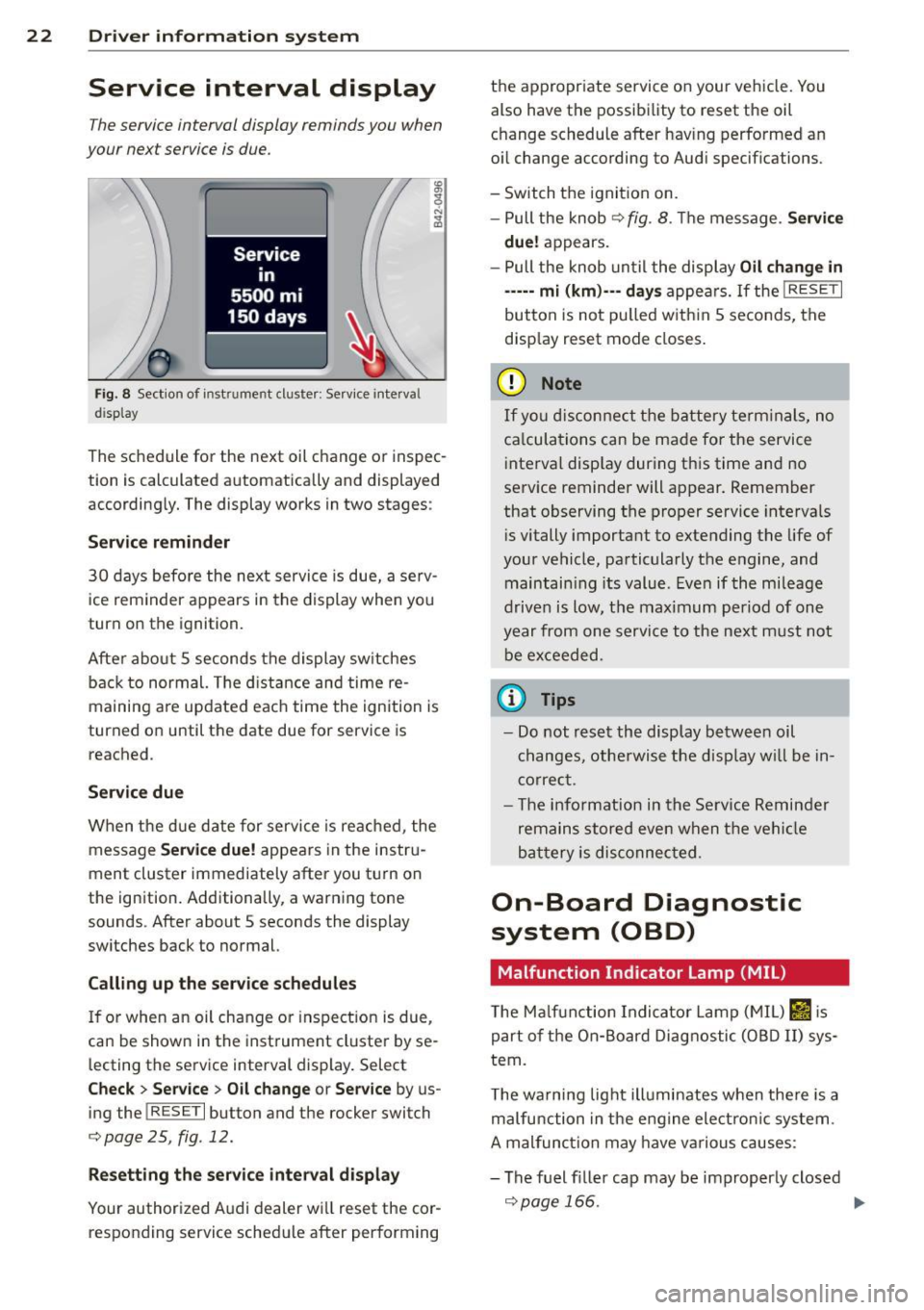
The service interval display reminds you when
your next service is due.
Fig. 8 Section of instr ume nt cluster : Service inte rva l
display
The schedule for the next oil change or inspec
tion is calculated automatically and displayed
according ly. The display works in two stages :
Service rem inder
30 days before the next service is due, a serv
ice reminder appears in the display when you
turn on the ignition.
After abo ut
S seconds the display sw itches
back to normal. The d istance and time re
maining are updated eac h time the ignition is
turned on until the date due for service is reached .
Service due
When the due date for service is re ached , the
message
S erv ice due! appears in the instru
ment cluster immediately after you tu rn on
the ignition. Additionally, a warn ing tone
sounds . After about
S seconds the display
switches back to normal.
Calling up th e servic e schedule s
If or when an oil change or inspection is due,
can be shown in the instrument cluster by se
l ecting the service interval display . Select
C heck > Service > Oil chang e or Service by us
ing the
! R ESE T I button and the rocker switch
c;,page25, fig.12.
Re setting the ser vice in te rv al di spla y
Your authorized A udi dealer w ill reset the cor
responding service sched ule after perform ing the appropr
iate service on your veh icle. You
also have the possibi lity to reset the oil
change schedule after hav ing performed an
o il change according to Aud i specif ications.
- Switch the ignition on.
- Pull the knob
¢ fig . 8 . The message . Service
due!
appears .
- Pull the knob until the display
Oi l change in
----- mi ( km)·-- day s
appears. If the I RESET I
button is not pu lled w ithin 5 seconds, the
disp lay reset mode closes .
(D Note
If you disconnect t he battery term inals, no
ca lcula tions can be made for the service
i nterval disp lay during th is time and no
service reminder will appear. Remember
that observing the proper service intervals
i s vitally important to extending the life of
your vehicle, pa rticularly the engine, and
maintain ing its value . Eve n if the mileage
drive n is low, t he maximum period of one
year from one servi ce to the next m ust no t
be exceeded.
(D Tips
- Do not reset the display b etwee n oil
changes, othe rwise the disp lay w ill be in
correc t.
- The information in the Service Reminder
remains stored eve n when t he vehi cle
ba ttery is disconnec ted.
On-Board Diagnostic
system (OBD)
Malfunction Indicator Lamp (MIL )
The Ma lf u nction Indi cato r Lamp ( MIL) II is
part of the On- Board Diagnostic (OBD II) sys
tem.
T he wa rni ng lig ht illuminates when the re is a
malfunction in the engine elect ro ni c system .
A mal func tion may have va rious causes :
- The f uel f iller cap may be improperly closed
c;, page 166. ..,.
Page 29 of 236

.. If necessary, scroll by se lecting and activat
ing the symbol for "Next page" or "Previous
page".
When you have selected the Computer menu
and activated it by pressing the
I RESET I but
ton, two computer leve ls appear (computer 1
and computer 2). Now you have to select the
level you want using the rocker switch and ac
tivate it w ith the
I RESET I button.
Lap timer
Introduction
The lap timer allows you to record and evalu
ate lap times .
The instrumen t cluster display shows the t ime
in m inutes, seconds and tenths o f a second.
For lap times longer than one hour, the hour
is also shown automatically. The maximum re
cordab le time for a single measurement is 99
h ours , 59 m inutes and 59 and 9/10 seconds.
If t he lap timer reaches th is value, the tim ing
stops on its own or it switches to pause mode
via
c::;, page 28.
A WARNING
Pl ease d evote your fu ll attent ion to driv
ing. As the d river, yo u have comp lete re
sponsibility fo r sa fe ty i n traffic. Only use
t he functions in such a way that you always
ma inta in complete control over your veh i-
de in all traff ic sit uat ions.
(D Tips
All of the trip compu ter functions are
availab le as usua l w hen the lap timer stop
watch is runn ing.
-
Dr iver in formation system 2 7
Selecting the lap timer
---®
Fig. 17 Contro ls
Fi g. 18 D isplay: Lap timer
.. With the ignition on, press the I RESET I b ut
ton @
r=;,fig . 17 unt il the lap timer r=;,fig. 18
appears.
Starting the timer
Fig. 19 D isplay: Lap 1
F ig . 20 D isplay: Lap 1 is saved, lap 2 is started
Page 32 of 236
30 Driver in formation sy ste m
each other and that have somewhat different
purposes:
Spee d warn ing 1 lDl/lOl ( Canada models )
You can use speed warning 1 to set the maxi
m um speed w hile you are driv ing. This sett ing
will remain in effe ct until you turn off the igni
tion, assuming that you have not changed or reset the setting .
The speed warning symbo l
(alllDl (Canada
models) in the warning 1 display appea rs
when you exceed the maxim um speed. It goes
out when the speed falls be low the stored
maximum speed.
The speed wa rning symbo l w ill also go out if
the speed
exceeds the stored maximum speed
by more than about 25 mph (40 km/h) for at
least 10 seconds. The stored maximum speed
is deleted.
Setting speed warning 1
c:>page 30.
Speed warning 2 lCl/EOl (Canada m odels )
Storing warning 2 is recommended if you al
ways
want to be remi nded of a certa in speed,
for example when you a re traveling i n a cou n
try that has a general maximum speed limit,
or if you do not want to exceed a specified
speed for winter tires.
The speed wa rning 2 symbol,
1a1;[i] (Canada
models) appears in the disp lay when you ex
ceed the stored speed limit . Unlike warn ing 1,
it will not go out unti l the vehicle speed drops
be low the stored speed limit.
Sett ing speed warning 2
c:> page 30 .
({) Tips
Even tho ugh you r vehicle is equipped with
a speed w arning sys tem, you should s till
watch the speedomete r to make sure you
are not driving faster tha n the speed limit.
Speed warning 1: setting a speed limit
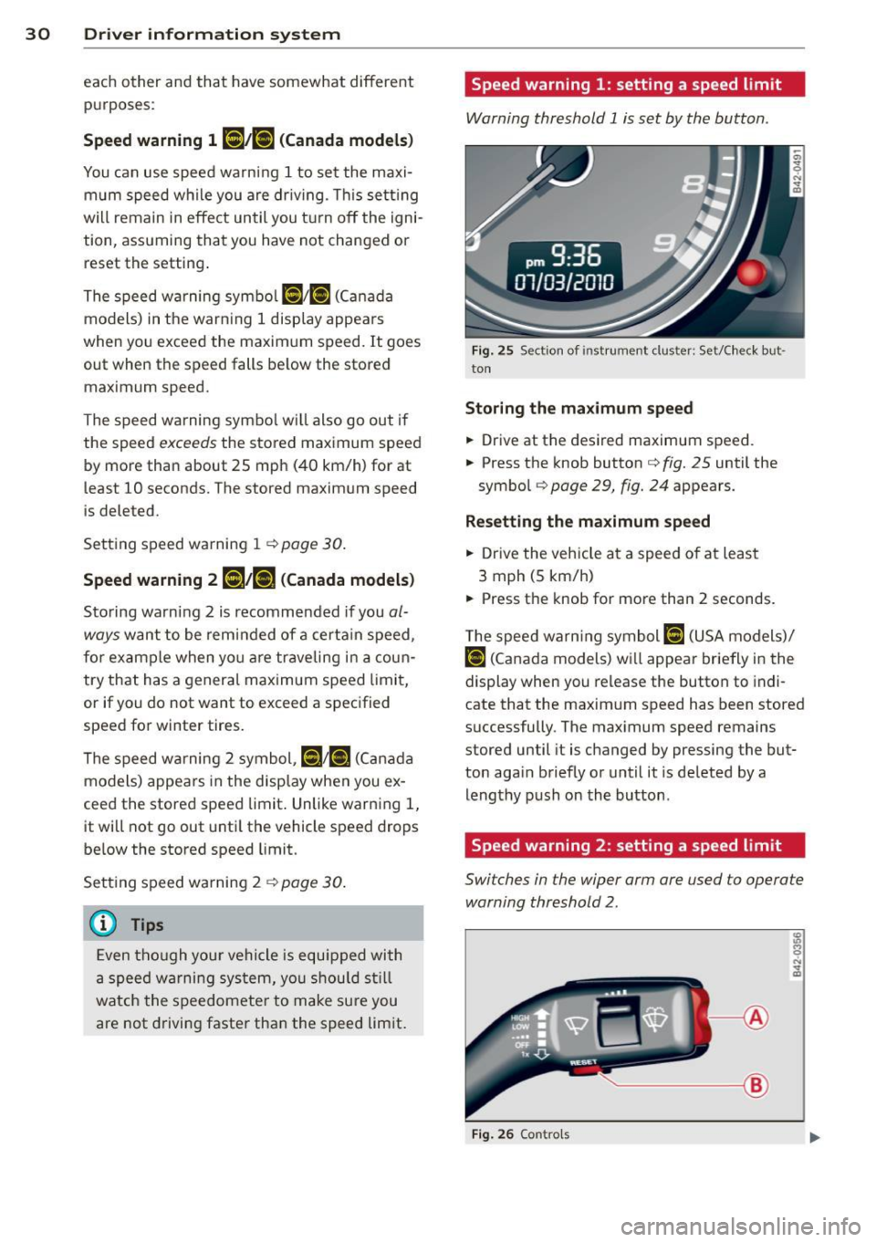
Warning threshold 1 is set by the button .
Fig. 25 Sect ion of instrument cluster: Set/Check but
ton
Storing the ma ximum speed
.,. Drive at the desired maximum speed.
.,. Press the knob button
c:> fig. 25 until the
symbo l
c:> page 29, fig. 24 appears.
Resett ing the maximum spe ed
.,. Drive the vehicle at a speed of at leas t
3 mph (5 km/h)
.,._ Press the knob for more than 2 seconds.
T he speed wa rn ing symbol
ID] (USA models)/
f•j (Canada models) wi ll appear briefly in the
display when you release the button to indi
cate that the maxim um speed has been stored
s uccessfully . The max imum speed remains
stored until it is changed by pressing the but
ton aga in briefly or unt il it is de leted by a
leng thy push on the button .
Speed warning 2: setting a speed limit
Switches in the wiper arm are used to operate
warning threshold 2.
----- @
Fig. 26 Contro ls
Page 54 of 236
52 Clear vis ion
Interior lights
Interior lights
The interior lights include the reading lights
for the driver and the front passenger .
-
,-i.-,-,n--;)
"' "' "' 0
•
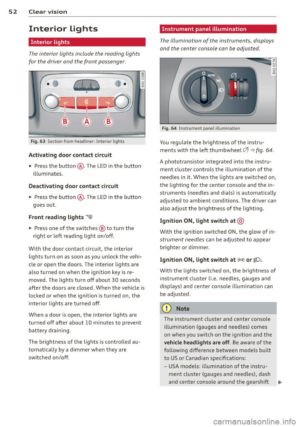
Fi g. 63 Section from headliner: I nterior l ights
Acti vating door contact circuit
• Press the button @. The LED in the button
i lluminates.
Deactivating door c ontact circu it
• Press the button @. The LED in the button
goes out .
Front re ad ing lights ~
• Press one of the switches @ to turn the
right or left reading light on/off.
With the door contact circuit, the interior lights turn on as soon as you unlock the vehi
cle or open the doors. The interior lights are
also turned on when the ignition key is re moved. The lights turn off about 30 seconds
after the doors are closed . When the vehicle is
locked or when the ignit io n is tu rned on, the
inte rior lights a re turned off.
When a door is open, the interior lights are
turned off after about 10 m inutes to prevent
battery drain ing.
The brightness of the lights is controlled au
tomatically by a dimmer when they are
switched on/off .
Instrument panel illumination
The illumination of the instruments, displays
and the center console can be adjusted .
Fig . 6 4 Instrument pa nel illuminat ion
You reg ulate the brightness of t he instr u
ments with the left thumbwheel
c;~-~ fig . 64 .
A phototransisto r integrated into the instru
ment cluster controls the illumina tion of the
need les in it. When the lights are switched on,
the lighting for the center conso le and the in
struments (needles and dials) is automatically
adjusted to ambient conditions . The driver can
also adjust the brightness of the lighting.
Ignition ON, light switch at @
With the ign ition sw itched O N, the g low of in
strument needles
can be adjusted to appear
brighter or dimmer.
Ignition ON, light switch at ;oo : or ~D.
With the lights switched o n, the br ightness of
instrumen t cluster ( i.e . need les, ga uges and
displays) and cen ter conso le illum inat ion can
be adjusted.
(D Note
The instrumen t cluster and cen ter conso le
ill umin ation (gauges and nee dles) comes
o n when yo u sw itch on the ignit io n and the
veh icle headlights are off . Be aware of the
fo llowing difference between models bui lt
to US or Canadian specifications:
- USA models: illumination of the instru
ment cl uster (gauges and need les), dash
and center conso le around the gearshift .,.
Page 55 of 236
lever is controlled by a light sensor locat
ed in the instrument panel. The instru
ment pane l illumination will a utomat i
cally become dimmer as the daylight
fades away and eventually will go o ut
completely when outside light is ve ry
low. T his is to rem ind you, the drive r, to
switch on the headlights before it gets
too dark.
- Canada models: instrument panel i llum i
nat io n w ill stay b right regard less of the
i n tens ity of amb ien t lig ht. Always be
aware o f ch anges in outside light con di
tions wh ile you are driving. Resp ond in
time to fading daylight by t urning the
l ight sw itch to position
io (or "A UTO" if
your car is equ ipped with this feature) to
turn on your headlights.
Luggage compartment light
The light is located on the right side of the
luggage compartment .
These lights come on automatica lly when the
front lid is opened. The lig hts turn off auto
mat ica lly if the lid is left open for more then
10 minutes.
Sun visors
CJ
C • -·-·--·,
~
-----____ ,,_
~ --·----"-------.. ----
~ ---- s;i~~~j
.---~~·-·oiiiiiii------------1
Fig. 6 5 Sun v isor
The vanity mir rors in the sun v isors are eq uip
ped with covers.
Clear vi sion 5 3
Wiper and washer
system
Windshield wiper
The windshield wiper lever controls both the
windshield wipers and the washer system.
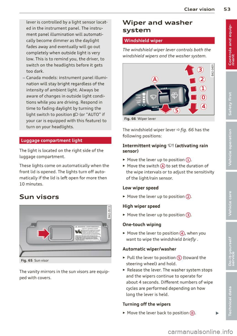
Fi g. 6 6 W iper leve r
The w indshield wiper lever¢ fig. 66 has the
follow ing pos itions:
Intermittent wiping 'Pl (activating rain
sen sor)
.,. Move the lever up to position (D .
.,. Move the switch @ to set the duration of
the wipe intervals or to adjust the sensitivity
of the light/rain sensor .
Low wiper speed
.,. Move the lever up to position @.
High wiper speed
.,. Move the lever up to pos ition @.
One-touch wiping
.,. Move the lever to positio n @, when you
want to wipe the windsh ield
briefly .
Automatic wip er/ washer
.,. Pull the lever to position ® (toward the
steering whee l) and hold .
.,. Release the lever. The washer system stops
and the wipers continue to operate for
about 4 seconds. Different numbers of wipe
cycles are pe rformed depending on how
long t he leve r is he ld.
Turning off the w ipe rs
.,. Move the lever back to position @.
Page 60 of 236
58 Clear vis ion
SE (Southeast), S (South), SW (Southwest),
W (West), NW (Northwest).
(D Tips
To avo id ina ccurate directions, do not a l
low any remote controls, electrical sys
tems, or metal parts close to t he mirror .
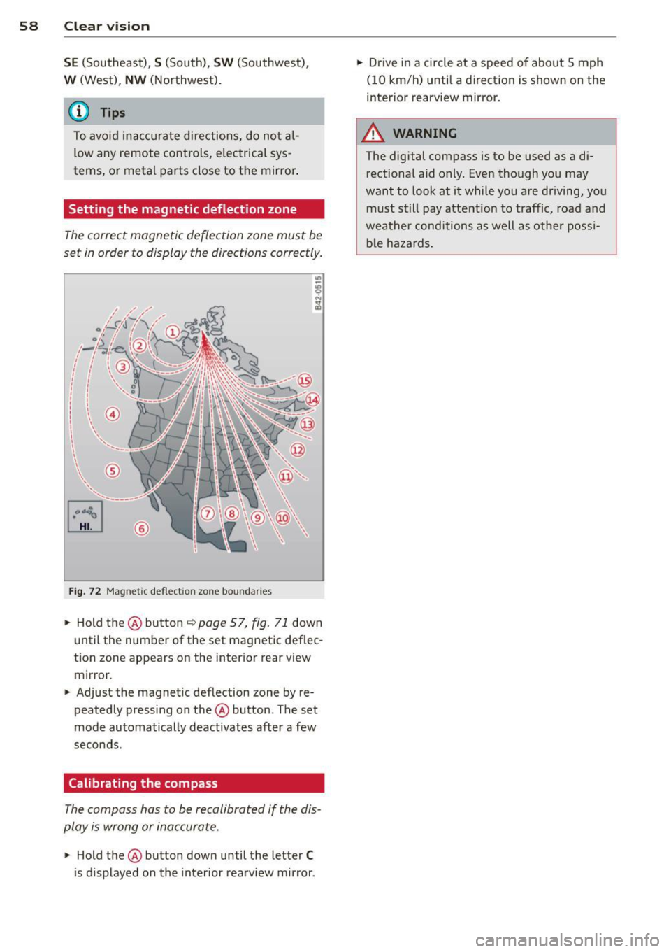
Setting the magnetic deflection zone
The correct magnetic deflection zone must be
set in order to display the directions correctly.
Fig . 72 Magne tic deflection zone boundaries
.. Hold the @button ~ page 57, fig . 71 down
until the number of the set magnetic deflec
tion zone appears on the interior rear view
mirror .
.. Adjust the magnetic deflection zone by re
peatedly pressing on the @button . The set
mode automatically deactivates after a few
seconds.
Calibrating the compass
The compass has to be recalibrated if the dis
play is wrong or inaccurate .
.. Hold the@ button down until the letter C
is displayed on the inte rior rearv iew mirro r. ..
Drive in a circle at a speed o f abo ut 5 mph
(10 km/h) until a direction is shown on the
interior rearview mirror .
_& WARNING
--
The digital compass is to be used as a di
rectional aid only. Even though you may
want to look at it while you are driving, you
must st ill pay atte ntion to traffic, road a nd
weather conditions as well as othe r possi
b le hazards.
Page 67 of 236
Warm and cold Climate controls
Controls
W arm and cold 65
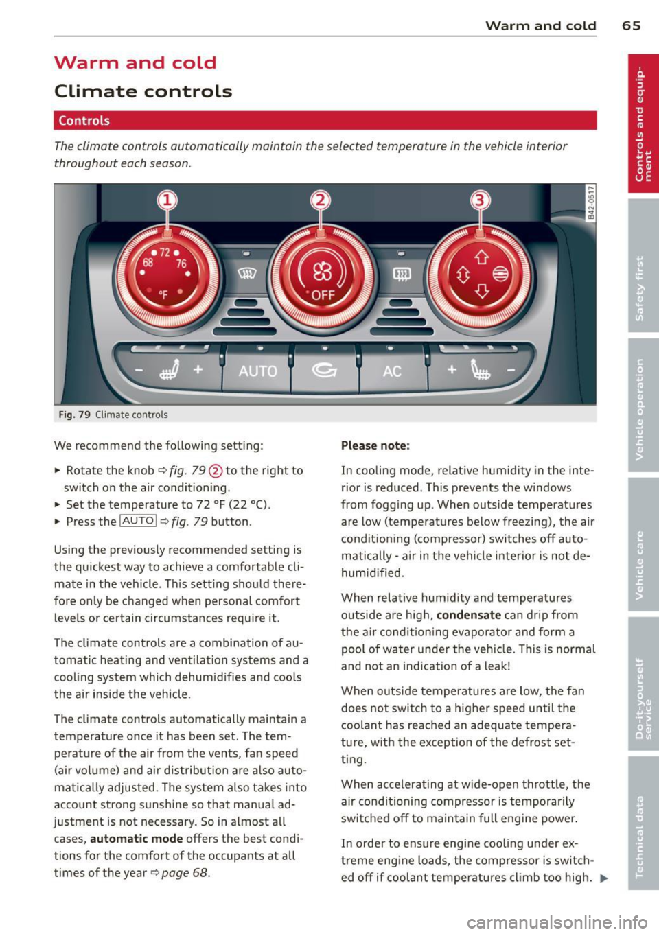
The climate controls automatically maintain the selected temperature in the vehicle interior
throughout each season .
Fig. 79 Climate contro ls
We recommend the following sett ing :
• Rotate the knob¢
fig. 79@ to the right to
switch on the air conditioning .
• Set the temperature to 72
°F (22 °().
• Press the !AUTO !¢ fig . 79 button .
Using the previously recommended setting is
the quickest way to achieve a comfortable cli
mate in the vehicle . Th is setting shou ld there
fore only be changed when persona l comfort
l eve ls o r ce rtain circumstances requ ire it .
The climate controls are a combination of au
tomatic heating and ventilation systems and a
cooling system which dehum idifies and coo ls
the air inside the vehicle .
The climate controls automatically maintain a temperature once it has been set. The tem
pe rat ure of the air from the v ents, fan speed
(air volume) and ai r distribu tion a re also auto
mat ica lly adjus ted . The system a lso takes into
account strong s unshine so that manua l ad
justment is not necessary . So in almost all
cases,
automatic mode offers the best cond i
tions for the comfort of the occupants at all
times of the year ¢
page 68.
Please note:
In cooling mode, relative humidity in the inte
r ior is reduced . This prevents the w indows
from fogg ing up . When outside temperatu res
ar e l ow (temperat ures below freezing), the air
cond it ion ing (compressor) switches off auto
matically - a ir in the vehicle interior is not de
humid ified.
When relative hum idity and tempera tures
outside are high,
c onden sate can drip from
t he a ir cond ition ing evaporator and form a
poo l of w at er unde r the ve hicle. This is normal
and not an ind ication of a leak!
When o uts ide temperatures are low, the fan
does not swi tch to a higher speed until the
coolant has reached an adequa te tempera
tu re, wit h the exception of the defrost set
ting.
When ac celera ting at w ide-open throttle, t he
air condi tioning compressor is temporar ily
swi tched off to ma intain full engine power .
In order to ensure engine coo ling under ex
t reme engine lo ads , the compressor is switch
ed off if coolant temperatures climb too hig h . ..,.
Page 70 of 236
68 Warm and cold
There are additional combinations (through
intermediate settings) avai lable to adjust air
d istribution as needed.
(D Tips
I f the climate cont rols are runn ing in cool
ing mo de, air shou ld flow mainly from
vents @and
@. To achieve suff ic ient coo l
ing, you shou ld neve r close these vents
comp letely .
Defrost ~
The windshield and side windows are defrost
ed or cleared of condensa tion a s quickly a s
possible.
.. To turn on the de fogger/defroster, press the
C!:J button c> page 65 , fig . 79 .
.,. To turn the defogger/defroster
off, press
the ~ button aga in , or the
!AU TO ! button .
Temperature is controlled automatically. The
maximum amount of a ir flows main ly from
ve nts 1
<=> page 67.
A sma ll amount of air flows from vents 2 -if
they are open
<=> page 67 .
P ress ing the ~ button switches
off recircu la
tion mode.
Automatic operation ~
Standard operating mode at all times of the
year.
Turning on automatic operation
.. Set the temperature you want .
.,. Press the
!AUTO I bu tton c> page 65, fig. 79.
Automatic operation ensures constant tem
pe ratures in the int erio r and dehum idifies the
a ir i nside t he vehi cle. Ai r temperature, vol
ume, and dist ribution a re controlled a utoma t
i ca lly to reach o r maintain the desire d interio r
temperature as q uickl y as possib le . Fluct ua
tions in exterior temperature and the effects
of tempe rat ur e from the position of the sun
are compensated for automat ica lly.
Manual air recirculation mode~
The recirculation mode prevents polluted out
side air from entering the vehicle interior.
Switching on air recirculation
.. Press the button ~ c> page 65 , fig. 79,
c> _& .
Switching off air recirculation
.,. Press the b utton !,.;,,I ag ain, or
.. Press the
!AU TO ! button, or
.. Press th e ~ button .
In recirc ulation mode, air is drawn from t he
vehicle interior, filte red, and recircula ted . We
recommend that yo u se lect rec irculatio n
mode
briefly <=>.&. under the fo llowing cond i
tions:
When driving thro ugh a tunne l or in a traff ic
jam so that exha ust fumes an d odors cannot
enter the vehicle inte rior.
A WARNING
You sho uld not use the recirculation mode
for an extended pe riod s ince no fresh air is
d rawn in, and with the air co ndit ioning
switched
off the windows can fog up - this
i nc reases the r is k of an accident!
A/C operation ~
Switching on A/C
.. Press t he !AC ! button c> page 65, fig . 79.
Switching A /C off
.. Press the !AC ! button again .
The cooling sys tem is swi tched on d uring A/C
operation - the heat ing and ventilation system
is contro lled automatically .
{I) Tips
If the LED in the sw itch stays on a fter A/C
ope ration has been switc hed
off( = switch
i ng the A/C
off), there is a fault in an air
cond itioning component. P lease cons ult .,.
Page 71 of 236
an authorized Audi dealer when there is an
operating prob lem.
Using the climate controls economically
Economical use of the climate controls helps
to save fuel.
When climate con trol is wor king in cool ing
mode, engine performance is red uced and
fuel consumption is affected. To keep the time
the air conditioning is on as short as possib le,
you shou ld do the fo llow ing:
.,. If you wo uld like to save f uel, sw itch the air
conditioning off .
.. If you open the windows whi le driving,
switch the air conditioning off.
.,. If the vehicle is extremely hot due to the
heat of the sun, briefly open doors and win
dows.
@ For the sake of the environment
When you save fuel, you reduce em iss ions
from the vehicle.
Rear window defogger
The rear window defogger clears the rear win
dow of condensation .
.. Press the Iii button <=> page 65, fig. 79 to
turn the rear window defogger on and off.
The rear window defogger wor ks only when
the eng ine is r unning. The indicator light in
the button illuminates when the rear window
defogger is turned on.
The rear window defogger is switched off au
tomatically after approx . 10 minutes .
@ For the sake of the environment
As soon as the rear window is clear, yo u
should switc h the rea r window de fogger
off . The reduced power consumption has a
beneficial effect on f uel consumption.
Warm and c old 69
Heated seats
Applies to vehicles: with heated seats
The seat cushion and the seatback of the
front seats can be heated electrically.
.. Press the heated seats button I-J + I
<=> page 65, fig . 79 to set the leve l of heating
desired.
The range of cont ro ls goes from 1 to 3. The
heat setting selected is shown by LEDs above
the button.
A WARNING
--=
Indiv iduals wit h reduced sens itiv ity to pa in
or temperature could deve lop burns when
using the seat heat ing funct ion. To reduce
the r isk of injury, these ind ividuals should
not use seat heating.
@ Note
To avoid damage to the heat ing e lements
i n the seats, do not kneel on the seats or
place heavy loads o n a small area of the
seat.
Page 84 of 236
82 Parking system
Parking system
Parking system
advanced
Introduction
Appl ies to vehicles: wit h park ing system advanced
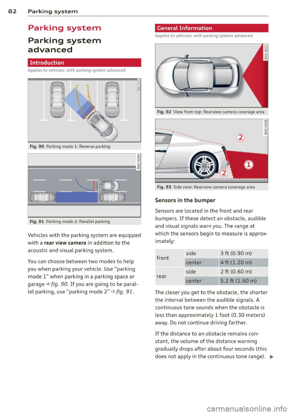
F ig. 90 Park ing mode 1: Reverse parking
;J
9 N
I!!!!!!!!!!!!!!!!!!!!!!!!!!!!!!!!!!!!!!!!!!!!!!!!!!!!!!!!!!!!!!!!!!!!!!!\
!!!!!!!!!!!!!!!!!!!!!!!!!!!!!!!!!!!!!!!!!!!!!!!!!!!!!!!!!! ,~
Fig. 91 Park ing mode 2: Paral lel park ing
Vehicles with the parking system are equipped
with a
rear view camera in addition to the
acoustic and visual park ing system .
You can choose between two modes to help
you when parking your vehicle . Use "parking
mode 1" when parking in a parking space or
garage ~
fig. 90. If you are going to be paral
l el parking, use "parking . mode 2"
~ fig. 91.
General Information
Applies to vehicles: w ith park ing system advanced
Fig. 92 View from top: Rea rview camera coverage area
-----·-·--
Fig. 93 Side view: Rea rv iew came ra coverage area
Sensors in the bumper
Sensors are located in the front and rear
bumpers. If these detect an obstacle, audible
and visual signals warn you. The range at
which the sensors begin to measure is approx
imately :
front side
3
ft (0.90 m)
center 4 ft (1.20 m)
side 2 ft
(0.60 m)
rear center 5.2 ft (1.60 m)
The closer you get to the obstacle, the shorter
the interval between the audible signals . A
continuous tone sounds when the obstacle is
less than approximately 1 foot (0.30 meters)
away. Do not continue dr iv ing farther .
If the distance to an obstacle remains con
sta nt, the volume of the distance warn ing
gradually drops after about four seconds (this
does not apply in the cont inuous tone range). ..,.