display AUDI RS5 COUPE 2015 User Guide
[x] Cancel search | Manufacturer: AUDI, Model Year: 2015, Model line: RS5 COUPE, Model: AUDI RS5 COUPE 2015Pages: 254, PDF Size: 64.12 MB
Page 27 of 254
M N
0:: loo ,...., \!) 1.1'1
N 1.1'1 ,....,
Single-trip memory (Trip computer 1)
The s ingle-t rip memory s to res the trip informa
tion from the time the ignition is tu rned on until
it is turned off. If the trip is continued
within 2
hours
from the time the ignition was turned off,
the new data w ill be included in the calculat ion of
the current trip information. If the trip is inter
rupted for
more than 2 hours the memory is re
set automat ically.
Total-trip memory (Trip computer 2)
Unlike the sing le-trip memory, the tota l-trip
memory is not reset automatically. Th is permits
you to evaluate your driving data for the entire pe riod between manual resets.
Operation
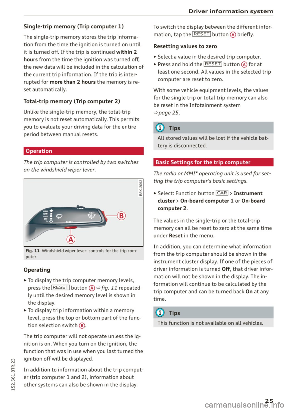
The trip computer is controlled by two switches
on the windshield wiper lever.
F ig. 11 Wind shield w iper lever: controls for the trip com
puter
Operating
.. To d isp lay the trip computer memory leve ls,
press the
I RESE T I button @¢ fig. 11 repeated
ly until the des ired memory level is shown in
the d isplay .
.. To display trip information w ith in a memory
level , press the top or bottom part of the func
t ion select io n switch @.
The trip computer will not operate unless the ig
nition is on. When you turn on the ignition, the
function that was in use when you last turned the
i gn ition off will be d isp layed.
In addition to information about the trip comput
er (tr ip computer 1 and 2), information about
other systems can also be shown in the display.
Driver information system
To switch the display between the different infor
mation, tap the
! RESET I button @briefly.
Resetting values to zero
"Select a value in the desired trip computer .
" Press and hold the
I RESET I button @for at
least one second. A ll values in the selected trip
computer are reset to zero .
With some vehi cle equ ipment levels, the values
for the single trip or total trip memory can also
be reset in the Infotainment system
¢page 25.
@ Tips
All stored values w ill be lost if the vehicle bat
tery is disconnected.
Basic Settings for the trip computer
The radio or MMI* operating unit is used for set
ting the trip computer's basic settings.
"Select: Function button !CAR !> Instrument
cluster> On-board computer
1 or On-board
computer
2 .
The values in the single-tr ip or the total-trip
memo ry can all be reset to zero at the same time
un der
Reset in the menu.
In add ition, you can determine what information
from the trip computer should be shown in the
i nst rumen t cl uste r display.
If one of the pieces of
drive r information is tu rned
Off , that driver infor
mation will not be shown in the display. The in
formation will continue to be calculated by the
trip computer and can be turned back
On at any
t ime.
(D Tips
This function is not available on all vehicles.
25
Page 28 of 254
Driver information system
Service interval display
The service interval display reminds you when
your next service is due.
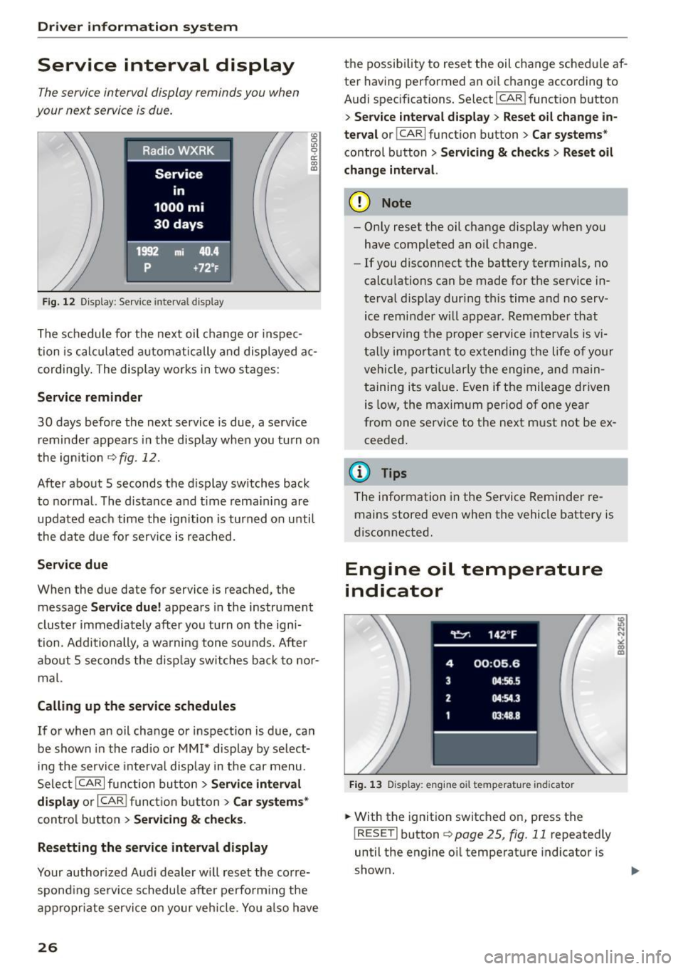
Fig. 12 Display: Service interva l display
"' 0 Ill 0 a: CX) (D
The schedule for the next oil change or inspec
tion is calculated automatically and displayed ac
cording ly. The display works in two stages :
Service reminder
30 days before the next service is due, a serv ice
reminder appears in the display when you turn on
the ignition
c> fig . 12.
After about 5 seconds the display switches back
to normal. The distance and time remaining are
updated each time the ignition is turned on unti l
the date due for serv ice is reached.
Service due
When the due date for service is reached, the
message
Service due! appears in the instrument
cluster immediately after you turn on the igni
tion . Additionally , a warning tone sounds. After
about 5 seconds the disp lay switches back to nor
mal.
Calling up the service schedules
If or when an oil change or inspection is due, can
be shown in the radio or
MM!* display by select
ing the service inte rval display in the car menu.
Select ICARI function button>
Service interval
display
or I CAR ! function button > Car systems*
control button > Servicing & checks.
Resetting the service interval display
Your authorized Audi dealer will reset the corre
spond ing serv ice schedule after perform ing the
appropriate service on your vehicle. You also have
26
the possibility to reset the oil change schedule af
ter having performed an oi l change according to
Audi specifications. Select
I CAR ! function button
> Service interval display> Reset oil change in
terval
o r! CAR i function button > Car systems *
control button > Servicing & checks > Reset oil
change interval.
(D Note
-Only reset the oil change display when you
have completed an oil change .
- If you disconnect the battery terminals, no
calculations can be made for the serv ice in
terval display during th is time and no serv
ice reminder will appear. Remember that
observing the proper service intervals is v i
tally impo rtant to extending the life of you r
vehicle, particularly the engine, and main
taining its value. Even if the mileage driven
is low, the maximum period of one year
from one service to the next must not be ex
ceeded.
(D Tips
The information in the Service Reminder re
mains stored
even when the vehicle battery is
disconnected.
Engine oil temperature
indicator
Fig. 13 Disp lay: eng ine o il temperature indicato r
.. With the ignition switched on, press the
! RESET! button
c> page 25, fig. 11 repeatedly
until the engine oil temperature indicator is
shown.
Page 29 of 254
"' N
0:: loo
rl I.O
"' N
"' rl
If the engine oil temperature is be low 140 ° F
(60 °C) , th <>
Ii symbol followed by three hy
phens"- --" and the °C un it is shown.
At an engine oil temperature above 140 °F
(60 °C) the engine has reached its operating tem
perature. The engine oil temperature may be
higher if there is heavy engine load and high tem
peratures outside. This is not a cause for concern
as long as the.
¢page 16 or the 1\1 ¢page 17
warn ing light in the display does not flash.
Lap timer
Introduction
You can record and evaluate lap times with the
lap timer in the display
¢page 27, fig. 15. The
time is measured in minutes, seconds and 1/10
seconds. The hou rs are also shown when the lap
time exceeds 60 minutes. The maximum individ
ual measurement is 99 hours. A maximum of 99 laps may be recorded.
A WARNING
Please devote your full a ttention to driving.
As the driver, you have comp lete responsib ili
ty for safety in traffic. Only use the functions
in such a way that you always ma inta in com
plete control over your vehicle in all traffic sit
uations .
(D Tips
When the lap timer stopwatch is running, you
can ca ll up the trip computer information
w ith the
! RESE T I button .
Calling up the lap timer and timing
Fig. 14 Contro ls
Dri ver information system
Fig. 15 Disp lay : Lap t imer
Calling up the lap timer
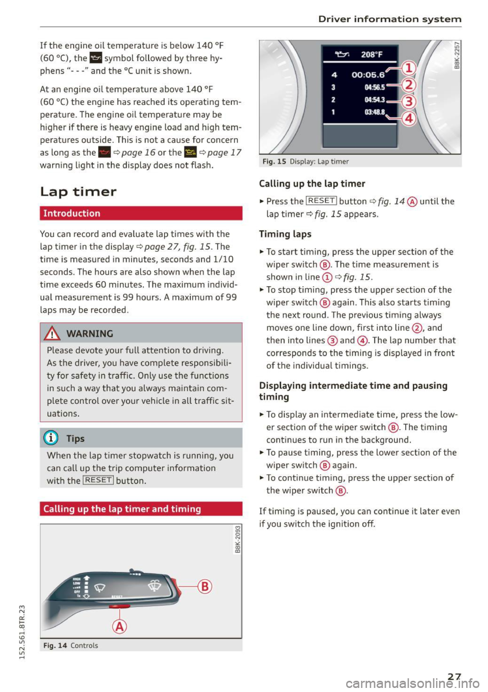
.,. Press the I RESET ! button ¢ fig. 14 @until the
lap timer ¢
fig. 15 appears .
Timing laps
.,. To start timing, press the upper section of the
w iper sw itch @. The time measurement is
shown in line
(D ¢ fig . 15.
.,. To stop timing, press the upper section of the
w iper sw itch @ aga in. This also starts timing
the next round. The previous timing always
moves one line down, first into line@, and
then into lines @ and @. The lap number that
corresponds to the timing is displayed in front
of the individual t imings.
Displaying intermediate time and pausing
timing
.,. To display an intermediate time, press the low
er section of the wiper switch @. The timing
continues to run in the background .
.,. To pause timing, press the lower section of the
w iper sw itch @ again .
.,. To continue tim ing, press the upper section of
the wiper switch @.
If timing is paused, you can continue it later even
if you sw itch the ignition off .
27
Page 30 of 254
Driver information system
Evaluating times and continuing or
resetting timing
You can evaluate the fastest, slowest and aver
age Lap times.
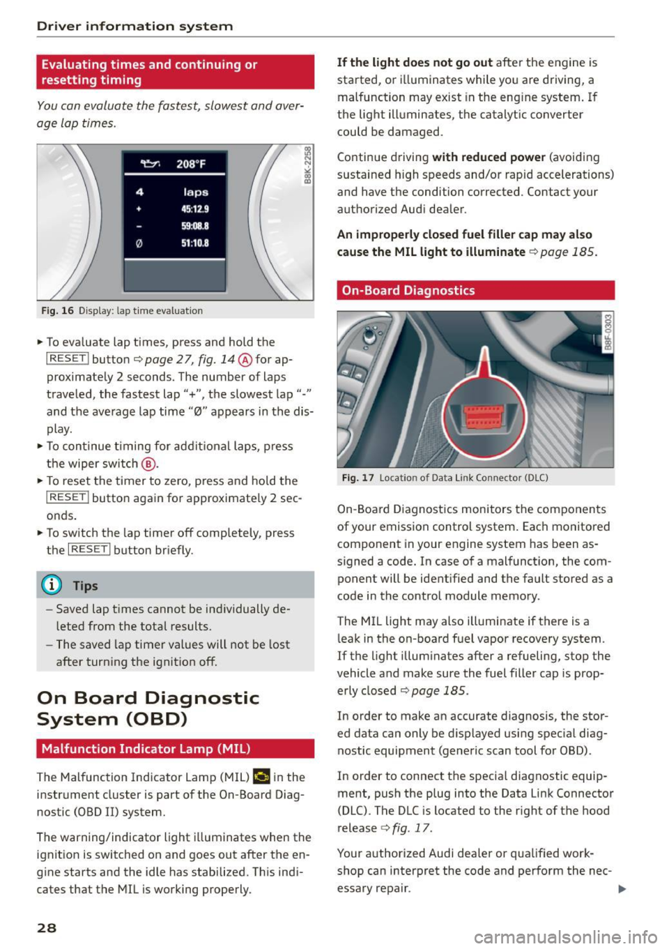
Fig . 16 D isplay: lap t ime evaluat ion
... To eva luate lap times, press and hold the
I RESET ! button c::;, page 2 7, fig. 14@for ap
proximately 2 seconds. The number of laps
traveled, the fastest lap"+", the slowest lap"-"
and the average lap time "0" appears in the dis
play .
... To continue timing for addit ional laps, press
the wiper sw itch @.
... To reset the timer to zero, press and hold the
I RESE T! button again for approximate ly 2 sec
onds .
... To switch the lap timer off completely, press
the
I RESE T I button briefly.
(D Tips
-Saved lap t imes cannot be ind ividually de
l eted from the total results.
- The saved lap timer values will not be lost
after turn ing the ignit ion off.
On Board Diagnostic
System (OBD)
Malfunction Indicator Lamp (MIL)
The Malfunction Indicator Lamp (MIL) ¢.ij in the
instrument cluster is part of the On-Board Diag
nostic (OBD II) system.
The warning/indicator light illuminates when the
ignit ion is switched on and goes out after the en
g ine starts and the idle has stabilized. Th is ind i
cates that the MIL is working properly.
28
If the light does not go out after the engine is
started, or i lluminates while you are driving, a
malfunction may exist in the eng ine system. If
the light illuminates, the catalytic converter
could be damaged .
Continue driving
with reduced power (avoiding
sustained high speeds and/or rapid accelerations)
and have the condition corrected. Contact your
authorized Audi dealer.
An improperly closed fuel filler cap may also
cause the MIL light to illuminate
c::;, page 185.
On-Board Diagnostics
Fig. 17 Locatio n of Data Link Co nnector (O LC)
On-Board Diagnostics monitors the components
of your emission control system. Each monitored component in your engine system has been as
signed a code. In case of a malfunction, the com ponent will be identified and the fault stored as a
code in the control module memory.
The MIL light may also illuminate if there is a
leak in the on-board fuel vapor recovery system.
If the l ight illuminates after a refueling, stop the
vehicle and make sure the fuel filler cap is prop
erly closed
c::;, page 185.
In order to make an accurate diagnosis, the stor
ed data can only be displayed using special diag
nostic equipment (generic scan tool for OBD).
In order to connect the specia l diagnostic equip
ment, push the plug into the Data Link Connector
(DLC). The DLC is located to the right of the hood
release
c::;, fig . 17 .
Your authorized Audi dealer or qua lified work
shop can interpret the code and perform the nec- essary repair . .,,_
Page 42 of 254
Opening and closing
The fo llowing buttons are deactivated when the
valet parking function is switched on:
-las l but ton in the dr iver's door
- la, l button on the master key
- Handle in the rear lid
When the valet parking feature is activated, the
message
Valet parking activated appears in the
instrument cluster display when you switch the
ignit ion on .
Garage door opener
(Homelink)
Description
Applies to vehicles: with garage door opener (Homelink)
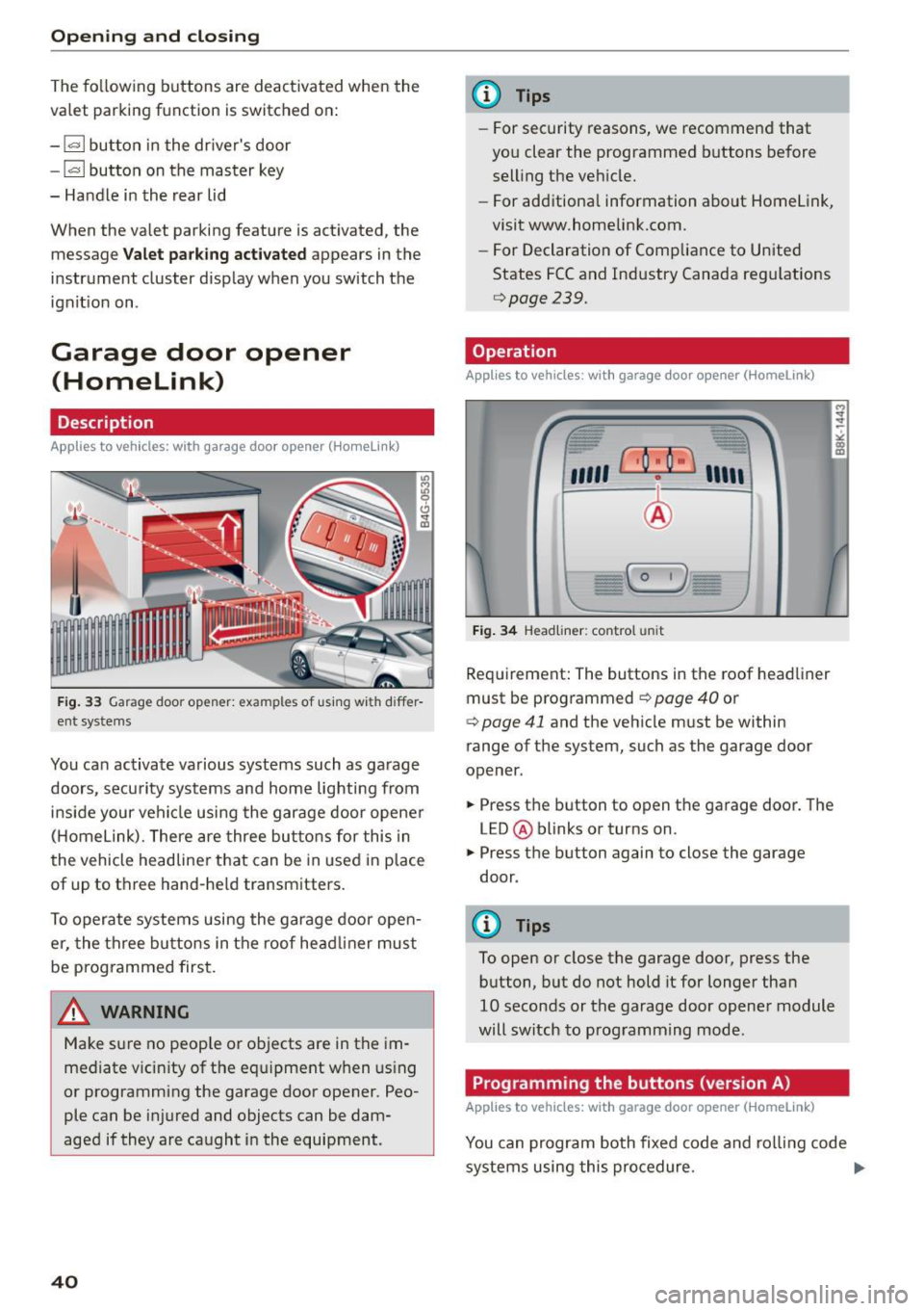
F ig. 33 Garage door opener: examples of using with differ
ent systems
You can activate various systems such as garage
doors, security systems and home lighting from
inside your vehicle using the garage door opener
(Homelink). There are three buttons for this in
the vehicle headliner that can be in used in place
of up to three hand-held transmitters.
To operate systems using the garage door open
er, the three buttons in the roof head liner must
be programmed first.
A WARNING
Make sure no people or objects are in the im
mediate v icin ity of the equipment when using
or programming the garage door opener. Peo
ple can be injured and objects can be dam
aged if they are caught in the equipment.
40
@ Tips
- For security reasons, we recommend that
you clear the programmed buttons before
selling the vehicle.
- For additional information about Homelink,
visit www.homelink.com.
- For Declaration of Comp liance to United
States FCC and Industry Canada regulations
9page239.
Operation
Appl ies to vehicles: with garage door opener (Homelink)
fr --= <• --- "' -
"'
"' ~
"' co m
''''' r · o : o ·) ,,,,;
-
I
~ I I
:'I
I
I - C 0 1)
)
Fig. 34 Headliner: co ntrol un it
Requirement: The buttons in the roof headliner
must be programmed
9 page 40 or
¢ page 41 and the vehicle must be within
range of the system, such as the garage door
opener.
.. Press the button to open the garage door. The
LED @ blinks or turns on.
.. Press the button again to close the garage
door .
@ Tips
To open or close the garage door, press the
button, but do not hold it for longer than
10 seconds or the garage door opener module
will switch to programming mode.
Programming the buttons (version A)
Applies to vehicles: with garage door opener (Homelink)
'
You can program both fixed code and rolling code
systems using this procedure. ..,_
Page 43 of 254
"' N
0:: loo
rl I.O
"' N
"' rl
Programming or reprogramming buttons
• Switch the ignition on.
• Press and hold the button in the roof head liner
r::!> page 40, fig. 34 that you would like to pro
gram for at least 10 seconds. Or
• Select :
ICARI function button> Car systems*
control button > Vehicle settings > Garage
door opener> Program garage door opener.
If
th is path is not available, program the button
as described in vers ion B
¢ page 41 .
• Follow the instructions in the MMI.
Erasing button programming
The programmed buttons cannot be erased indi
vidually . They must all be erased together . Repro
gram the buttons if necessary .
• Select :
ICARI function button> Car systems*
control button > Vehicle settings > Garage
door opener> Clear program settings > Yes.
Displaying the version/status/country code
• Se lect: I CAR I function button > Car systems*
control button > Vehicle settings > Garage
door opener > Version information.
@ Tips
- Programming through the MM!* is not pos
sible with all infotainment systems. If this
is the case, program the buttons as descri
bed in version B ¢
page 41.
-The requ ired distance between the hand
transmitter and the HomeLink module in
the radiator grille
c> page 41, fig . 35 de
pends on the system that you are program
ming .
- Depending on the model of the system, you
may need to release the button on the re
mote control during programming and
press it again. Hold each position you try for
at leas t 15 seconds before trying another
position. Keep the turn signals on your vehi
cle in view when doing this.
- After programming the garage door opener,
i t may be necessary to synchronize the mo
tor with the system. Refer to the manufac
turer's instructions.
Opening and closing
Programming the buttons (version B)
Applies to vehicles: with garage door opener (Hornelink)
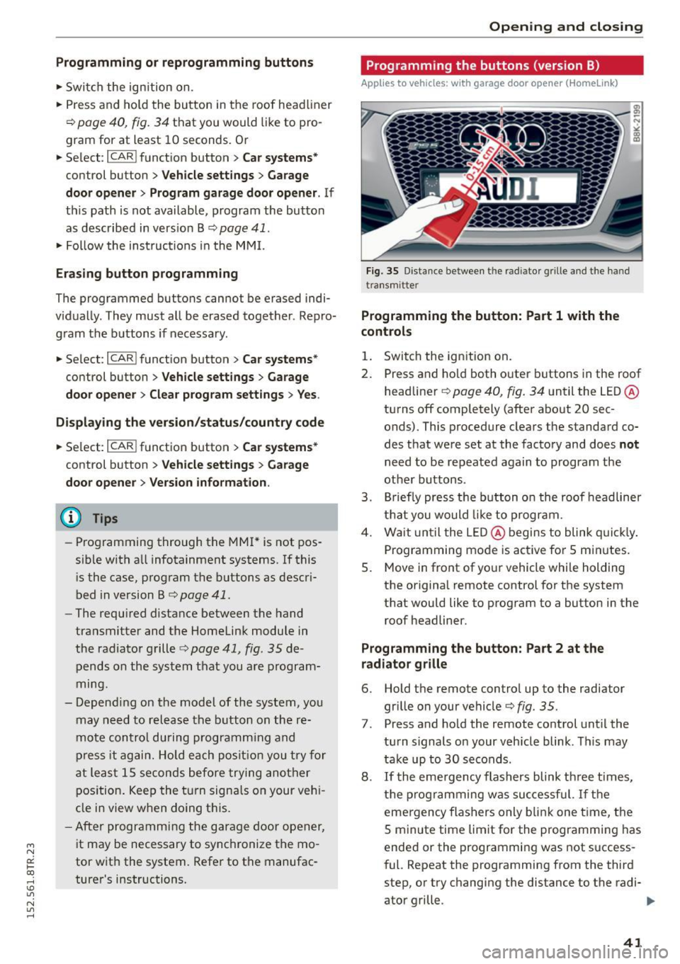
Fig. 35 Distance between th e rad ia to r g ri lle a nd the han d
t ra nsmitte r
Programming the button: Part 1 with the
controls
1. Switch the ign ition on.
2. Press and ho ld both outer buttons in the roof
headliner
c> page 40, fig. 34 until the LED @
turns off completely (after about 20 sec onds). This procedure clears the standard co
des that were set at the factory and does
not
need to be repeated again to program the
other buttons .
3. Briefly press the button on the roof headliner
that you would like to program.
4. Wait until the LED @ begins to blink quickly.
Programming mode is active for 5 minutes .
5. Move in front of yo ur vehicle whi le holding
the original remote control for the system
that would like to program to a button in the roof headliner.
Programming the button: Part 2 at the
radiator grille
6. Hold the remote control up to the radiator
grille on your vehicle¢
fig. 35.
7. Press and ho ld the remote control until the
turn signals on your veh icle blink . This may
take up to 30 seconds .
8.
If the emergency flashers blink three times,
the programming was successful. If the
emergency flashers only blink one t ime, the
5 minute time limit for the programming has
ended or the programming was not success
ful. Repeat the prog ramming from the third
step, or try changing the distance to the radi- ator grille . .,..
41
Page 47 of 254
"' N
0:: loo
rl I.O
"' N
"' rl
The coming home and leaving home functions
only operate when it is dark and the light switch
is in the AUTO position ¢
page 43, fig. 36.
Auto headlights*
When the light switch is in the AUTO¢ page 43
position, the switch-on point of the lights can be
changed in the automatic driving light function.
Daytime running lights
USA models: You can switch the daytime running
lights
on and off.
Canada models: The function cannot be turned
off. It is activated automatically each time the ig nition is switched on.
Travel mode*
The headlight beam is asymmetrical. This pro
vides stronger illum ination on the s ide of the
road on which you are driving. If you are driving
in a country that drives on the opposite side of
the road from your own country, this will cause
glare for oncoming drivers. To prevent glare:
- Travel mode must be selected in vehicles with
Xenon headlights*.
- In vehicles with halogen headlights, certain
areas of the headlight lenses must be covered
with waterproof adhesive covers that prevent light from passing through . For more informa
tion, please see your authorized Audi dealer or authorized repair facility.
(0 Tips
When travel mode is activated, a display in
the driver information system indicates this
each time you switch the ignition on.
Lights and Vision
Emergency flashers
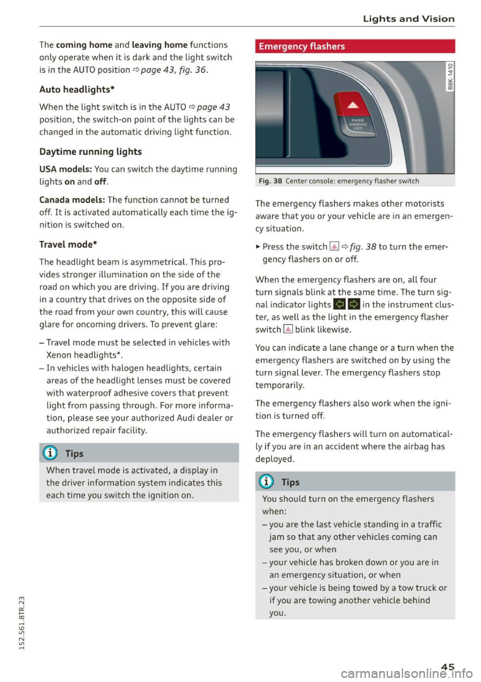
Fig. 38 Center console: emergency flasher switch
The emergency flashers makes other motorists
aware that you or your vehicle are in an emergen
cy situation .
.. Press the switch~ ¢
fig. 38 to turn the emer-
gency flashe rs on or off.
When the emergency flashers are on, all four
turn signals blink at the same time. The turn sig
nal indicator lights
R 1B in the instr ument clus
ter, as well as the light in the emergency flasher
switch
Gil blink likewise .
You can indicate a lane change or a turn when the emergency flashers are switched on by using the
turn signal lever. The emergency flashers stop
temporarily.
The emergency flashers also work when the igni
t ion is turned off.
The emergency flashers will turn on automatical
ly if you are in an accident where the airbag has
deployed .
(D Tips
You should turn on the emergency flashers
when:
- you are the last vehicle standing in a traffic
jam so that any other vehicles coming can see you, or when
- your vehicle has broken down or you are in
an emergency situation, or when
- your vehicle is being towed by a tow truck or
if you are towing another vehicle behind
you.
45
Page 48 of 254
Lights and Vi sion
Interior Lighting
Front/rear interior lights
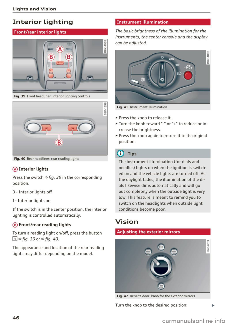
Fig. 39 Fr on t headliner : interior lig htin g contro ls
F ig. 40 Rear head liner: rear read ing lig hts
@ Interior lights
Press the switch c:> fig. 39 in the corresponding
posi tion .
0 -Inte rior lights off
I -Interior ligh ts on
If the sw itch is in the center position, the interio r
lig hti ng is controlled automatically.
@ Front/rear reading lights
To turn a reading light on/off, press the button
l:!l c:> fig. 39 or c:> fig. 40 .
The appearance and location of the rear reading
lights may differ depending on the model.
46
Instrument illumination
The basic brightness of the illumination for the
instruments, the center console and the display
can be adjusted .
Fig. 4 1 Ins trume nt illum in ati on
.,. Press t he knob to re lease it .
.,. Turn the knob toward" -" or"+" to reduce or i n
crease the brightness .
.,. Press the knob again to return i t to its origina l
position .
(!) Tips
The instrument illum inat ion (for dials and
needles) lights o n when the ignition is switch
ed on and the vehicle lights are turned off. As
the daylight fades , the illum inat ion of the di
a ls likewise dims automatically an d wi ll go
out comple tely w hen t he ou tside light is very
l ow. This fe ature is me ant to remind yo u to
switc h on the headlights when ou tside light
cond itions become poor.
Vision
Adjusting the exterior mirrors
Fig . 42 D rive r's doo r: knob fo r the exter io r mi rrors
Turn the knob to t he des ired pos it io n:
Page 54 of 254

Lights and Vi sion
Adjusting the magnetic zone
Applies to vehicles: with digital compass
The magnetic zone must be adjusted correctly
for the compass to read accurately .
~
LIU ®
Fig . SO No rth A meri ca: magne tic deflection zo ne bo unda
ri es
"' Press a nd ho ld the button @~ fig. 50 until the
number of the magne tic zone ap pears in the
rearview mirror .
"' Press the butto n @ repeated ly to select the
correct magnetic zone . The selection mode
turns off after a few seconds.
Calibrating the compass
Applies to vehicles: w ith d ig ital compass
You must recalibrate the compass if it does not
display the correct direction.
"'Press and ho ld the bu tton @unt il a C appea rs
in the rearview mirror.
"' Drive in a circle at about 6 mph (10 km/h) until
a direct ion is displayed in the rearv iew m irror .
A WARNING
-To avoid endanger ing yo urself and othe r
dr ivers, calibrate the compass i n an area
whe re the re is no traffic.
52
- The digital compass is to be used as a direc
tional a id on ly. Even though you may want
to look at it wh ile you are dr iv ing, you must
still pay attent io n to traffic, road a nd weath
er cond itions as well as other poss ible haz
ar ds.
Page 70 of 254

Warm and cold
Operation
We recommend pressing the !AU TO ! button and setting the temperature to 72 °F (22 °C).
Fig . 72 Automatic climate control sys tem: control
F ig . 73 3-zone del ux e automat ic climate controt•: controls
Press the buttons to turn the functions on or off.
Use the dials to adj ust the temperature, the
b lo wer speed and the air distribution. The LED in
a button will light up when the function is
switched on. The settings are displayed for a few
seconds in the radio or MMI* display.
In vehicles with a 3-zone deluxe automatic cli
mate control systems*, the driver and front pas
senger side can be adjusted sepa rately. The set
tings are also disp layed in the climate control
system display .
68
I OFFI Switching the climate control system
on/off
The ! OFF ! button switches the climate contro l
system on or off.
It also switches on when you
press the knob. Airflow from outside is blocked
when the cl imate control system is switched off.
IA/C l Switching cooling mode on/off
The air is not cooled and humidity is not removed
when coo ling mode is switched off. This can
cause fog on the windows. The cooling mode is
switched off automatically at low outside tem
peratures.