battery AUDI RS5 COUPE 2015 Owners Manual
[x] Cancel search | Manufacturer: AUDI, Model Year: 2015, Model line: RS5 COUPE, Model: AUDI RS5 COUPE 2015Pages: 254, PDF Size: 64.12 MB
Page 5 of 254
M N
0:: loo ,....,
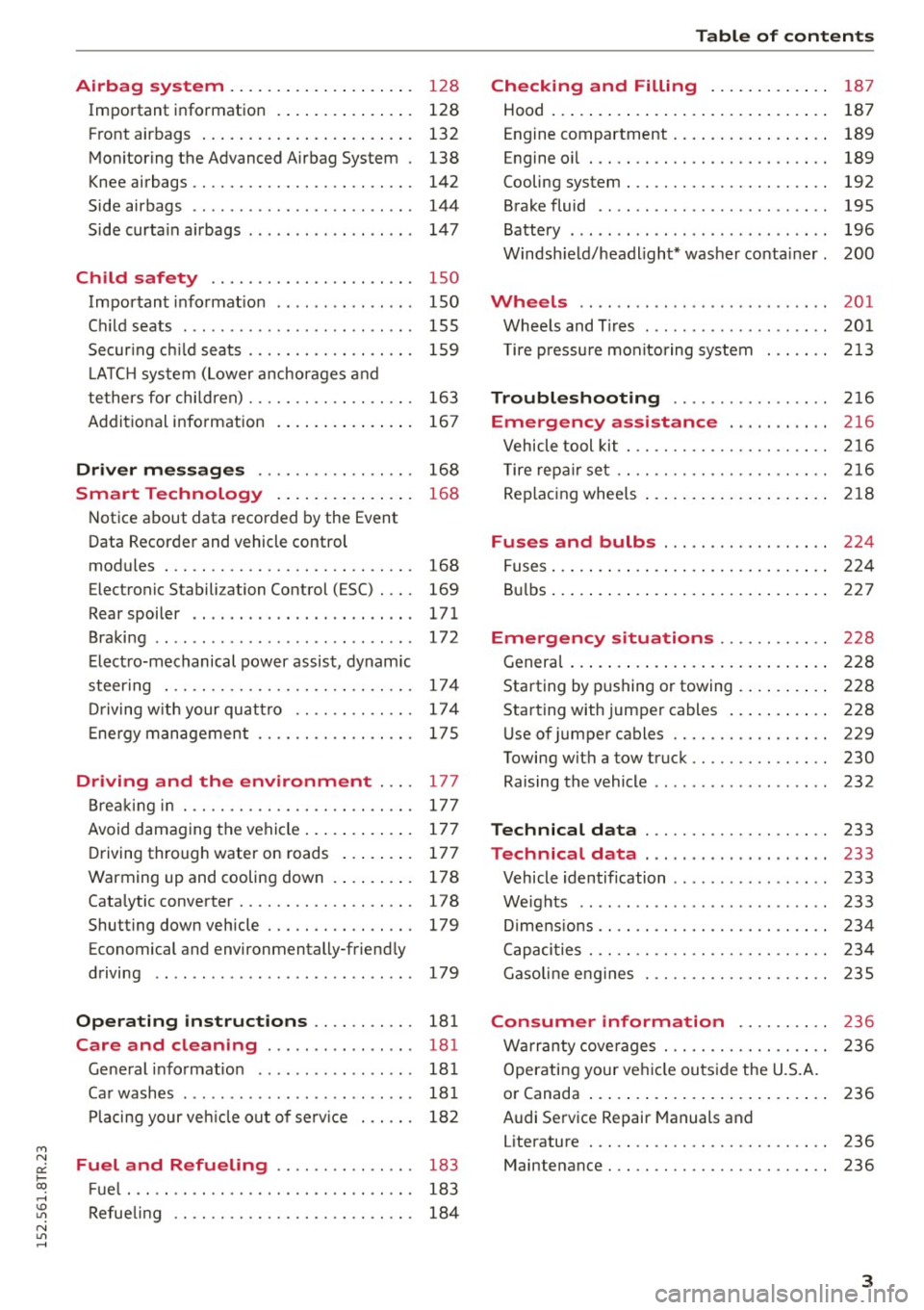
Airbag system . . . . . . . . . . . . . . . . . . . . 128
Important information . . . . . . . . . . . . . . . 128
Front ai rbags . . . . . . . . . . . . . . . . . . . . . . . 132
Mon ito ring the Advanced A irb ag Sys tem . 138
Knee airbags . . . . . . . . . . . . . . . . . . . . . . . . 142
Side airbags . . . . . . . . . . . . . . . . . . . . . . . . 144
Side curta in a irbags . . . . . . . . . . . . . . . . . . 1 47
Ch ild safety . . . . . . . . . . . . . . . . . . . . . . 150
Important informat ion . . . . . . . . . . . . . . . 150
Ch ild seats . . . . . . . . . . . . . . . . . . . . . . . . . 155
Secur ing c hild seats . . . . . . . . . . . . . . . . . . 159
L A TC H system (Lower anchorages and
tethers for chi ldren) . . . . . . . . . . . . . . . . . . 163
Addit ional info rmation
167
Driver messages . . . . . . . . . . . . . . . . . 168
Smart Technology . . . . . . . . . . . . . . . 16 8
N otice about data recorded by the Event
Data Recorder and vehicle cont rol
modules . . . . . . . . . . . . . . . . . . . . . . . . . . . 168
Electronic Stabili za tion Control (ESC) . . . . 169
Rear spoiler . . . . . . . . . . . . . . . . . . . . . . . . 171
Braking . . . . . . . . . . . . . . . . . . . . . . . . . . . . 172
Elect ro-mechanical power assist , dynamic
steer ing . . . . . . . . . . . . . . . . . . . . . . . . . . . 174
Dr iving w ith your quat tro . . . . . . . . . . . . . 17 4
E ne rgy management . . . . . . . . . . . . . . . . . 17 5
Driving and the environment . . . . 177
B rea kin g in . . . . . . . . . . . . . . . . . . . . . . . . . 177
Avoid damaging the vehi cle . . . . . . . . . . . . 17 7
D riving through water on roads . . . . . . . . 177
Warming up and cooling down . . . . . . . . . 178
Cata lytic converter........ .... .. .. .. . 17 8
Shutt ing down veh icle . . . . . . . . . . . . . . . . 179
Economical and environmentally-friend ly
driving . . . . . . . . . . . . . . . . . . . . . . . . . . . . 179
Operating instructions . . . . . . . . . . . 181
Care and cleaning . . . . . . . . . . . . . . . . 181
Ge ne ral i nfo rmat ion . . . . . . . . . . . . . . . . . 181
Ca r washes ............... ...... ... .
Pl acing your veh icle out of se rv ice 18
1
18 2
Fuel and Refueling . . . . . . . . . . . . . . . 183
F ue l... .. .. ................. .. .... . 183
~ Refue ling . . . . . . . . . . . . . . . . . . . . . . . . . . 184
N l/'I ,....,
Tab le of conten ts
Checking and Filling . . . . . . . . . . . . .
187
Hood . . . . . . . . . . . . . . . . . . . . . . . . . . . . . . 187
Engine compartment . . . . . . . . . . . . . . . . . 189
Engine oil . . . . . . . . . . . . . . . . . . . . . . . . . . 189
Cooling system . . . . . . . . . . . . . . . . . . . . . . 192
Brake fluid . . . . . . . . . . . . . . . . . . . . . . . . . 195
Battery . . . . . . . . . . . . . . . . . . . . . . . . . . . . 196
Windsh ie ld/headlight* washer conta iner. 200
Wheels .. .. .. .. .. ... .. ... ..... .. .. 201
Whee ls and T ires . . . . . . . . . . . . . . . . . . . . 201
T ire pressu re monito ring system 213
Troubleshoot ing .............. ... 216
Emergency assistance ... .. .. ... . 216
Vehicle tool kit . . . . . . . . . . . . . . . . . . . . . . 216
T ire repa ir set .. . .. .......... .... .. . . 216
Rep lac ing whee ls . . . . . . . . . . . . . . . . . . . . 2 18
Fuses and bulbs . . . . . . . . . . . . . . . . . . 224
F uses ... .. .. .. .. .. .... .... ... .. .. .. 224
B ul bs . . . . . . . . . . . . . . . . . . . . . . . . . . . . . . 2 27
Emergency situations . . . . . . . . . . . . 228
Genera l . . . . . . . . . . . . . . . . . . . . . . . . . . . . 2 28
Starting by pushing or towing . . . . . . . . . . 228
Starting with jumper cabl es . . . . . . . . . . . 228
U se of jumper cables . . . . . . . . . . . . . . . . . 229
Towing with a tow truck . . . . . . . . . . . . . . . 230
Raising the vehicle . . . . . . . . . . . . . . . . . . . 232
Technical data . . . . . . . . . . . . . . . . . . . . 233
Technical data . . . . . . . . . . . . . . . . . . . . 233
Vehicle identification . . . . . . . . . . . . . . . . . 233
Weights . . . . . . . . . . . . . . . . . . . . . . . . . . . 233
D imens io ns . . . . . . . . . . . . . . . . . . . . . . . . . 234
Capaci ties . . . . . . . . . . . . . . . . . . . . . . . . . . 234
Gasoli ne engines . . . . . . . . . . . . . . . . . . . . 235
Consumer information . . . . . . . . . . 236
W arranty cove rages . . . . . . . . . . . . . . . . . . 236
Operatin g your ve hicl e outs ide the U.S.A.
o r Canada . . . . . . . . . . . . . . . . . . . . . . . . . . 236
Audi Se rvice Repair Manuals and
Literature . . . . . . . . . . . . . . . . . . . . . . . . . . 236
Maintenance . . . . . . . . . . . . . . . . . . . . . . . . 236
3
Page 15 of 254
M N
0:: loo ,...., \!) 1.1"1
N 1.1"1 ,....,
Indicator lights
Description
The indicator lights in the instrument cluster
blink or turn on. They indicate functions or mal
functions¢ &.
Messages may appear with some indicator lights .
A warning signal will sound at the same time.
The messages disappear again after a short time.
To display a message again, press the
I SE TI but
ton ¢
page 11. If several malfunctions occur,
each of the indicator/warning lamps will be dis
p layed in succession for about two seconds at a
time.
Some indicators lights in the display can turn on
in several colors.
8_ WARNING
- Failure to heed warning lights and other im
portant vehicle information may resu lt in
serious personal injury or vehicle damage.
- Whenever sta lled or stopped for repa ir,
move the vehicle a safe distance off the
road, stop the engine, and turn on the emer
gency flasher¢
page 45.
- The engine compartment of any motor vehi
cle is a potentially hazardous area. Before
you check anything in the engine compart
ment, stop the engine and let it cool down.
Always exercise extreme caution when work
ing under the hood¢
page 187.
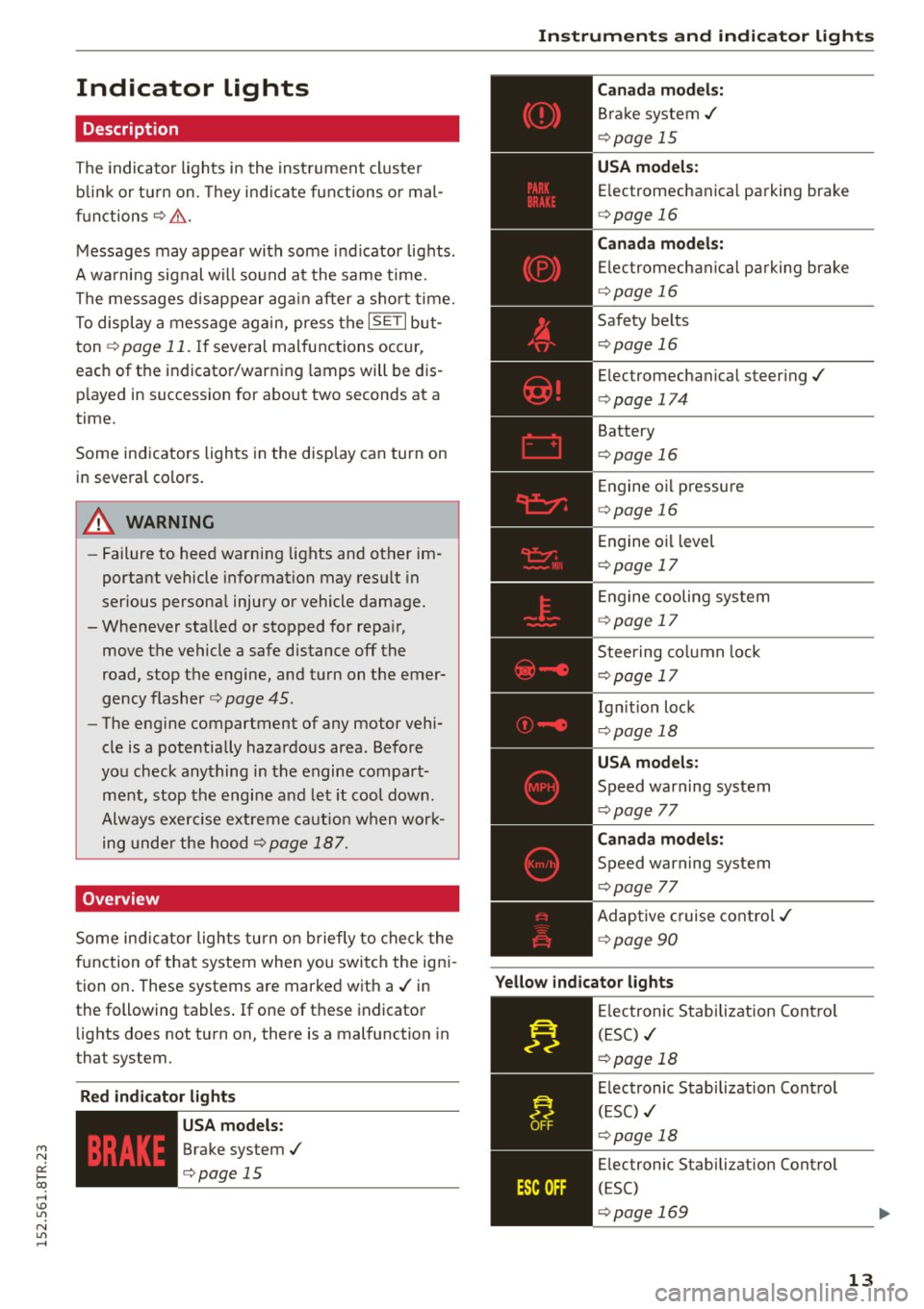
Overview
Some indicator lights turn on briefly to check the
function of that system when you switch the igni
tion on . These systems are marked with a./ in
the following tables .
If one of these indicator
lights does not turn on, there is a malfunction in
that system.
Red indicator light s
--------------
US A models:
Brake system./
¢page 15 Instruments
and indicator lights
Canada models:
Brake system./
¢page 15
USA models:
Electromechanical parking brake
¢ page 16
Canada models:
Electromechanical parking brake
¢ page 16
Safety belts
¢page 16
Electromechanical steering./
¢page 174
Battery
¢page 16
Engine oil pressure
¢page 16
Engine oil level
¢page 17
Engine cooling system
¢page 17
Steering column lock
¢page 17
Ign it ion lock
¢ page 18
USA models:
Speed warning system
¢page 77
Canad a models:
Speed warning system
¢page 77
Adaptive cruise control./
¢page 90
Yellow indicator lights
--------------
Electronic Stabilization Contro l
(ESC) ./
¢page 18
Electronic Stabilization Contro l
(ESC) ./
¢page 18
Electronic Stabilization Control
(ESC)
¢page 169
13
Page 16 of 254
Instruments and indicator lights
"O~ I I ~ .,
TPMS
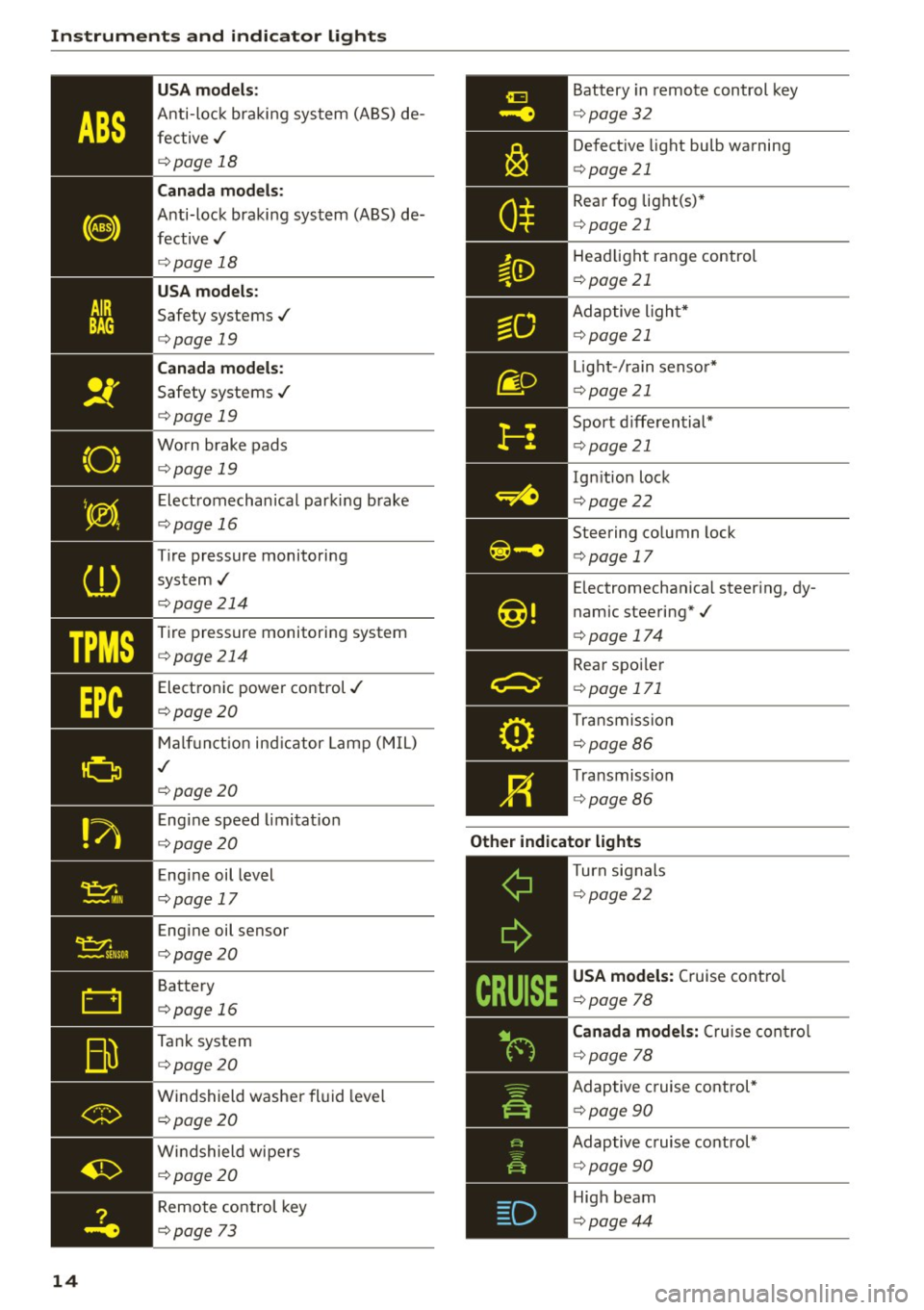
14 USA m
odel s:
Anti-loc k braking system (ABS) de
fective,/
¢ page 18
Canada mod els :
Anti-lock braking system (ABS) de
fective,/
¢ page 18
USA models :
Safety systems,/
¢page 19
Canada model s:
Safety systems ./
¢page 19
Worn brake pads
¢ page 19
Electromechanical parking b rake
¢page 16
Tire pressure monitoring
system,/
¢ page214
Tire pressure monitoring system
¢page214
Electronic power control./
¢page20
Malf unct ion ind icator Lamp (MIL)
,I
c::>page 20
Engine speed limitat ion
c::> page20
Engine oil level
c::> page 17
Engine oil sensor
c::>page20
Battery
c::>page 16
Tank system
c::>page20
Windshield washe r fl uid leve l
¢page20
Wi ndshield wipers
¢page20
Remote control key
c>page 73
Battery in remote control key
¢ page32
Defect ive light bulb warning
¢ page 21
Rear fog lig ht(s)*
<=> page 21
Headlight range control
¢page 21
Adaptive l ight*
c> page 21
Light -/ rain senso r*
c> page 21
Sport d iffe rential*
c> page 21
Ignition lock
c>page22
Steering co lumn lock
c> page 17
Electromechanica l steer ing, dy
namic steering*,/
c>page 174
Rear spo ile r
c> page 171
Transmission
c>page86
Transmission
c>page 86
Other indicator light s
--------------Turn signals
c>page22
USA models: Cruise contro l
c>page 78
Canad a model s: C ru ise contro l
c>page 78
Adaptive c ruise cont rol*
c> page 90
Adaptive c ruise control*
c> page 90
High beam
c>page44
Page 18 of 254
Instruments and indicator lights
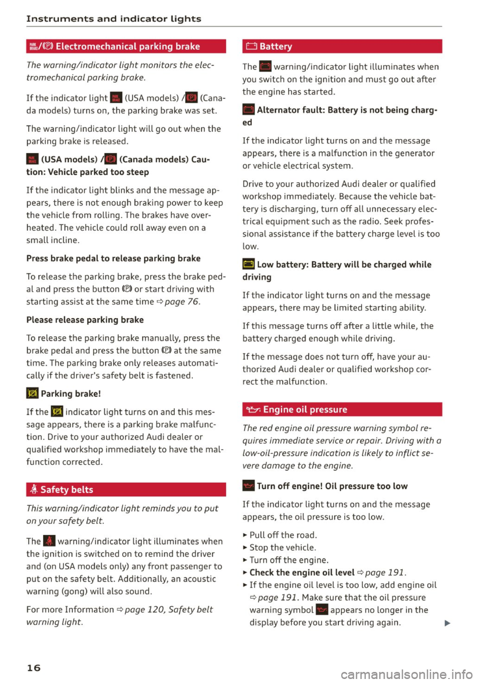
l:.'J,/(® ) Electromechanical parking brake
Th e w arning/indicator light monitors th e elec
tromechanical parking brake.
If the indicator light . (USA models)/ . (Cana
da models) turns on, the parking brake was set.
The warning/indicator light will go o ut when the
parking brake is re leased.
• (USA models) ;a (Canada model s) Ca u
tion : Vehicle parked too steep
If th e i nd ic ator lig ht blinks and t he message ap
pe ars, there is not enoug h brak ing power to keep
t he vehicle from roll ing. The b ra kes have over
heated . The vehicle cou ld roll away even on a
sma ll incline.
Press brake p edal to relea se parking brake
To release the parking brake, press t he brake ped
a l and press the button(®) or start driving with
start ing assist at the same time ~
page 76.
Ple ase release park ing brake
To release the parking brake man ua lly, press the
brake peda l and press the button(®) at the same
time. The park ing brake only releases automat i
cally if the driver's safety be lt is fastened.
l'iJ Parking brake!
If th e II indicator ligh t turns on and thi s mes
sage ap pears , the re is a parking b rake ma lf u nc
tion. D rive to your authorized A udi dealer o r
qualified wor kshop immediate ly to have the mal
function corrected .
t Safety belts
This warning/indicator light reminds you to put
on your safety belt.
The . warning/in dicator light ill uminates when
the ignition is switched on to remind the drive r
and (on USA models on ly) any front passenger to
put on the safety belt. Add itionally, an acoustic
warn ing (gong) will also sound.
F or mo re Information ~
page 120, Safety belt
warning light.
16
0 Battery
The . war ning/ indica to r li ght illum ina tes w hen
yo u sw itch on the ig nition and m ust go ou t aft er
the engine has star ted.
• Alternator fault : Battery is not being charg·
ed
If the indicato r light turns on and the message
appears, there is a malfunct io n in the gene rator
o r vehicle e lectr ica l system .
Drive to your authorized A udi dealer or qualified
workshop immediately . Beca use the vehicle bat
te ry is d ischarging, tur n off all unnecessary elec
t rical eq uipme nt such as th e radio. Se ek prof es
s io nal assis tance if the battery cha rge leve l is too
l ow .
(•) low battery: Battery will be charged while
driving
If the indicator light turns on and the message
appears , there may be limited starting ab ility .
If this message t urns off after a little while , the
battery charged eno ugh while dr iv ing .
If the message does not turn off, have yo ur au
thorized Audi dea ler or qualified workshop co r
r ect the malfunction .
~ Engine oil pressure
The red engine oil pressure warning symbol re
quires immediate service or repair. Driving with a
low-oil-pressure indication is likely to inflict se
vere damage to the engine .
• Turn off engine! Oil pressure too low
If the indic ator li ght turns on and the message
appe ars, the o il pressure is too low.
~ Pull off the road .
~ Stop the vehicle .
~Tur noff the engi ne.
~ Che ck the engine oil level~ page 191.
~ If the eng ine o il level is too low, add eng ine oil
~ page 191. M ake sure that the oil p ress ure
warning symbol. appears no longer in the
disp lay before you start driving aga in. ..,_
Page 28 of 254
Driver information system
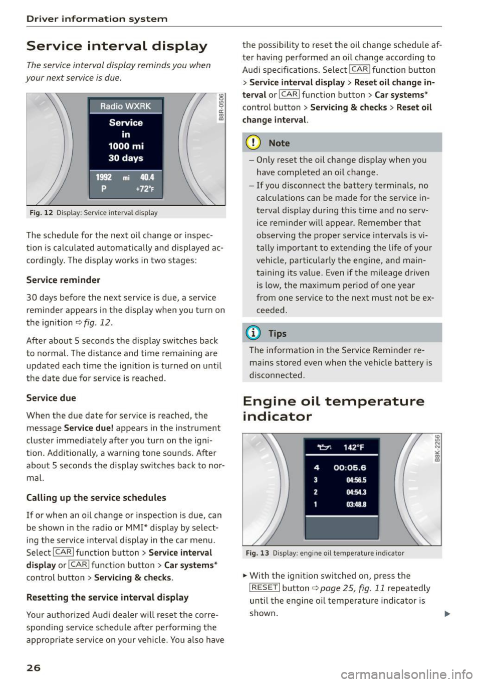
Service interval display
The service interval display reminds you when
your next service is due.
Fig. 12 Display: Service interva l display
"' 0 Ill 0 a: CX) (D
The schedule for the next oil change or inspec
tion is calculated automatically and displayed ac
cording ly. The display works in two stages :
Service reminder
30 days before the next service is due, a serv ice
reminder appears in the display when you turn on
the ignition
c> fig . 12.
After about 5 seconds the display switches back
to normal. The distance and time remaining are
updated each time the ignition is turned on unti l
the date due for serv ice is reached.
Service due
When the due date for service is reached, the
message
Service due! appears in the instrument
cluster immediately after you turn on the igni
tion . Additionally , a warning tone sounds. After
about 5 seconds the disp lay switches back to nor
mal.
Calling up the service schedules
If or when an oil change or inspection is due, can
be shown in the radio or
MM!* display by select
ing the service inte rval display in the car menu.
Select ICARI function button>
Service interval
display
or I CAR ! function button > Car systems*
control button > Servicing & checks.
Resetting the service interval display
Your authorized Audi dealer will reset the corre
spond ing serv ice schedule after perform ing the
appropriate service on your vehicle. You also have
26
the possibility to reset the oil change schedule af
ter having performed an oi l change according to
Audi specifications. Select
I CAR ! function button
> Service interval display> Reset oil change in
terval
o r! CAR i function button > Car systems *
control button > Servicing & checks > Reset oil
change interval.
(D Note
-Only reset the oil change display when you
have completed an oil change .
- If you disconnect the battery terminals, no
calculations can be made for the serv ice in
terval display during th is time and no serv
ice reminder will appear. Remember that
observing the proper service intervals is v i
tally impo rtant to extending the life of you r
vehicle, particularly the engine, and main
taining its value. Even if the mileage driven
is low, the maximum period of one year
from one service to the next must not be ex
ceeded.
(D Tips
The information in the Service Reminder re
mains stored
even when the vehicle battery is
disconnected.
Engine oil temperature
indicator
Fig. 13 Disp lay: eng ine o il temperature indicato r
.. With the ignition switched on, press the
! RESET! button
c> page 25, fig. 11 repeatedly
until the engine oil temperature indicator is
shown.
Page 34 of 254
Opening and closing
- Do not remove the key from the ignition lock
unt il the vehicle has come to a complete
stop. Otherwise the steering column lock
could sudden ly engage - causing the risk of
an accident.
(D Tips
- The operati on of the remote control key can
be temporar ily disrupted by i nte rference
from t ransmitters in the v ici ni ty of the ve hi
cle wor king in the same frequency range
(e .g . a cel l phone, rad io equipm ent) .
- Fo r secu rity reasons, replacement keys are
o nly availabl e from authori zed A udi dealer .
- Fo r Declarat ion of Compliance to United
Sta tes FCC an d Industry Canada regulations
<::;> page 239 .
Removing the mechanical key
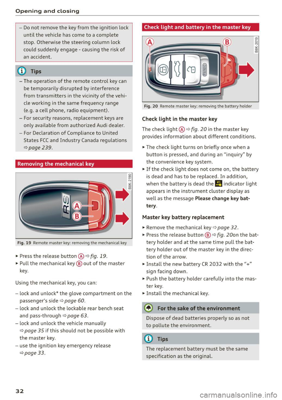
Fig . 19 Rem ote maste r key : rem ov ing th e m ec hani ca l key
.,. Press the release button@ c> fig. 19 .
.,. Pu ll t he mecha nica l key @ out of the master
key.
Using the mecha nica l key , you can:
- lock and unlock * the glove com partment on t he
passenger's side c>
page 60.
-lock and unlock the lockable rear bench seat
and pass-th rough ¢
page 63.
-lock and unlock the ve hicle manually
¢page 35 if this sho uld not be poss ible with
the maste r key.
- use the ign ition key emergency release
¢ page 3 3.
32
Check light and battery in the master key
Fig. 20 Remote maste r key: re m ovin g th e bat tery hol der
Check light in the ma ster key
The check light@c> fig. 20 in the master key
provides information about different conditions.
.,. The check light turns on br iefly once w he n a
button is pressed, and during an "inquiry" by
the convenience key system .
.,. If the check light does not come on, the battery
is dead and has to be replaced . In addit ion,
when the battery is dead the
!I i ndicator light
appears in the instr ument cluster d isp lay as
we ll as the message
Please change key bat
tery .
Master key battery replacement
.,. Remove the mechanical key c> page 32 .
.,. Press the release b utton @ c> fig. 20on the bat
t e ry ho lde r and at the same time pull the bat
t ery ho lde r out of the maste r key in t he d irec
t ion of the arrow .
.,. Insta ll th e new ba ttery CR 20 32 wi th t he "+"
sign facing down .
.,. Push the battery holder carefu lly into the mas
ter key.
.,. Install the mechanical key.
(® For the sake of the environment
Dispose of dead batteries properly so as not
to po llute t he environment.
@ Tips
The replacement battery must be the same
spec ificat ion as t he or igina l.
Page 36 of 254
Open ing a nd clos ing
¢ .&. in General description on page 30. Do not
reach inside the door handle.
The vehicle can be locked and unlocked at any door. The remote control key cannot be more
than 1.5 m away from the door hand le . It makes
no difference whether the master key is in your
jacket pocket or in your brief case .
I f you grip the door handle while locking, this can
adversely affect the locking function.
It is not possible to re-open the door for a brief
period directly after closi ng it . This allows you to
ensure that the doors are properly locked.
It depends on the sett ings i n the radio or MM !*
whether the entire vehicle is unlocked or one of
the doors ¢
page 35.
A WARNING
Read and follow all WARNINGS ¢.& in Gener
al description on page 30.
(D Tips
I f your vehicle has been stand ing fo r an ex
tended period, please note the fol low ing :
- The proxim ity sensors are deactivated after
a few days to save power. You then have to p ull on the door handle once to unlock the
vehicle and a second time to open t he vehi
cle.
- To prevent the battery from being dis
charged and to preserve your vehicle's abili
ty to start for as long as possible, the ener
gy management system gradually switches
off unnecessary convenience functions.
It is
possib le that you will not be able to unlock
your vehicle using these convenience func
tions .
- For Declaration of Compliance to United
States FCC and Industry Canada regulations
¢ page 239.
34
Locking and unlocking the vehicle from
inside
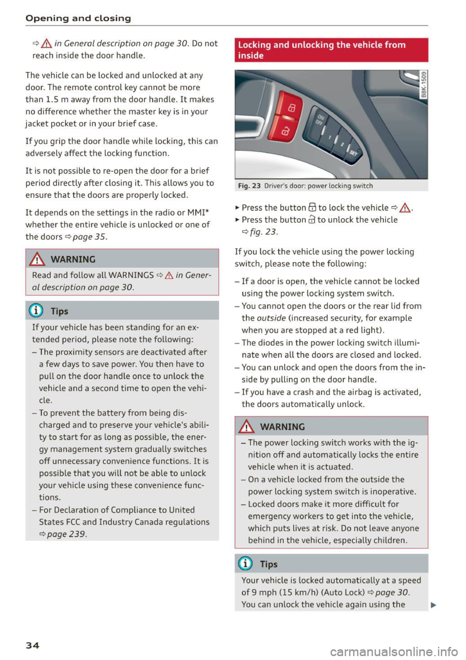
Fig. 23 Driver's doo r: power lock ing sw itch
.,. Press the button@ to lock the vehicle¢_&. .
.,. Press the button@ to unlock the vehicle
¢fig. 23 .
If you lock the veh icle using the power locking
switch , please note the following:
- If a door is open, the veh icle cannot be locked
using the power lock ing system switch.
- You cannot open the doors or the rear lid from
the
outside (increased security, for example
when you are stopped at a red light) .
- The d iodes in the power locking switch illumi
nate when all the doors are closed and locked .
- You can unlock and open the doors from the in
side by pulling on the doo r handle .
-If you have a crash and the airbag is activated,
the doors automatically unlock .
A WARNING
- The power locking switch works with the ig
nition off and automatically locks the entire
vehicle when it is actuated.
- On a vehicle locked from the outside the
power locking system switch is inoperat ive .
- Locked doors make it more difficult for
emergency workers to get into the veh icle,
which puts lives at r isk. Do not leave anyone
be hind in the veh icle, especially children .
('O Tips
Your vehicle is locked automatically at a speed
of 9 mph (15 km/h) (Auto Lock) ¢
page 30.
You can unlock the veh icle aga in using the ..,.
Page 40 of 254
Open in g and cl osin g
"' Pull the switch briefly to the se con d sto p to au
tomatically close the window.
A WARNING
- When you leave your vehicle -even if only
briefly -always remove the ignition key. This
applies part icularly when children remain in
the vehicle. Otherwise the children could start the engine or operate electr ical equip
ment (e.g. power w indows). The power win
dows are functional until the driver's door o r
passenger's door has been opened.
- Pay close atten tion when closing the w in
dows to prevent pinch ing of hands or limbs.
- When locking the vehicle from outs ide, the
vehicle must be unoccupied since the win dows can no longer be opened in an emer
gency.
(I) Tips
- When you open the doo rs, the windows au
tomatically lower about 10 mm.
- After the ignition has been switched off, the
windows can st ill be opened or closed for
about 10 m inutes. The window regulators
are not switched until the dr iver's or pas
senger's door is opened .
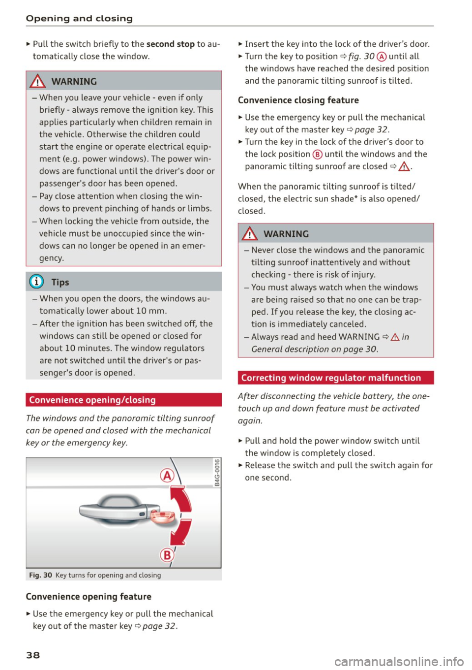
Convenience opening/closing
The windows and the panoramic tilting sunroof
can be opened and closed with the mechanical
key or the emergency key.
F ig. 30 Key turns fo r opening a nd clos ing
Conveni ence opening fe ature
"' Use the emergency key or pull the mechanical
key out of the master key
c> page 32 .
38
"'Insert the key into the lock of the driver's door .
"' Turn the key to position ¢
fig. 30 ® unti l all
the windows have reached the des ired pos ition
and the panoramic tilting sunroof is t ilted.
Con veni ence clo sing f eatur e
"'Use the emergency key or pull the mechanical
key out of the master key ¢
page 32.
"'Turn the key in the lock of the driver's door to
the lock position @ unti l the windows and the
panoramic tilting sunroof are closed
c> ,& .
When the panoramic tilting sunroof is tilted/
closed, the electric sun shade* is also opened/
closed.
A WARNING
- Never close the windows and the panoram ic
tilting sunroof inattentively and without
checking -there is risk of injury .
- You must always watch when the w indows
are be ing raised so that no one can be trap
ped. If you release the key, the closing ac
tion is immed iate ly canceled .
- Always read and heed WARN ING
c> A in
General description on page 30.
Correcting window regulator malfunction
After disconnecting the vehicle battery , the one
touch up and down feature must be activated
agatn.
"' Pull and ho ld the power window sw itch until
the window is completely closed .
"' Release the sw itch and pull the sw itch again for
one second .
Page 102 of 254
Audi side assist
(D Tips
-Side assist is not active while you are mak
ing the adjustment.
- Your settings are automatically stored and
assigned to the remote control key being
used.
Driver messages
Applies to veh icles: w ith Aud i side ass ist
If side assist switches off by itself, the LED in the
button turns
off and a message will appear in the
instrument cluster display:
Audi side assist unavailable: Sensors blocked
The radar sensors' vision is affected. Do not cover
the area in front of the sensors with bike wheels,
stickers, dirt or other objects. Clean the area in
front of the sensors, if necessary ¢
page 98,
fig. 104.
Audi side assist: Currently unavailable
Side assist cannot be switched on temporarily be
cause there is a malfunction (for example, the
battery charge level may be too low).
Audi side assist: System fault!
The system cannot guarantee that it will detect
vehicles correctly and it is switched off . The sen
sors have been displaced or are faulty. Have the
system checked by an authorized Audi dealer or
authorized Audi Service Facility soon.
100
Page 143 of 254

M N
0:: loo ,...., \!) 1.1"1
N 1.1"1 ,....,
@ Tips
If the weight-sensing mat in the front passen
ger seat detects an empty seat, the front air
bag on the passenger side will be turned off,
and
PASSENGER AIR BAG OFF will stay on.
Repair, care and disposal of the airbags
Parts of the airbag system are installed at many
different places on your Audi. Installing, remov ing , servicing or repairing a part in an area of the
vehicle can damage a part of an airbag system and prevent that system from working properly in a collision.
There are some important things you have to know to make sure that the effectiveness of the
system will not be impaired and that discarded
components do not cause injury or pollute the
environment.
A WARNING
-
Improper care, servicing and repair proce
dures can increase the risk of personal injury
and death by preventing an airbag from de
ploying when needed or deploying an airbag
unexpectedly:
- Never cover, obstruct, or change the steer
ing wheel horn pad or airbag cover or the in
strument panel or modify them in any way .
- Never attach any objects such as cup holders
or telephone mountings to the surfaces cov
ering the airbag units .
- For cleaning the horn pad or instrument panel, use only a soft, dry cloth or one mois
tened with plain water. Solvents or cleaners could damage the airbag cover or change
the stiffness or strength of the material so
that the airbag cannot deploy and protect
properly.
- Never repair, adjust, or change any parts of
the airbag system.
- All work on the steering wheel, instrument
panel, front seats or electrical system (in
cluding the installation of audio equipment,
cellular telephones and CB radios, etc.)
must be performed by a qualified technician
Airbag system
who has the training and special equipment
necessary.
- For any work on the airbag system, we
strongly recommend that you see your au
thorized Audi dealer or qualified workshop.
- Never modify the front bumper or parts of
the vehicle body.
- Always make sure that the side airbag can
inflate without interference:
- Never install seat covers or replacement
upholstery over the front seatbacks that
have not been specifically approved by
Audi .
- Never use additional seat cushions that
cover the areas where the side airbags in
flate.
- Damage to the original seat covers or to
the seam in the area of the side airbag
module must always be repaired immedi
ately by an authorized Audi dealer.
- The airbag system can be activated only
once. After an airbag has inflated, it must
be replaced by an authorized Audi dealer or
qualified technician who has the technical
information, training and special equipment
necessary.
- The airbag system can be deployed only
once . After an airbag has been deployed, it
must be replaced with new replacement
parts designed and approved especially for
your Audi model version. Replacement of complete airbag systems or airbag components must be performed by qualified work
shops only. Make sure that any airbag serv
ice action is entered in your Audi Warranty
&
Maintenance booklet under AIRBAG RE
PLACEMENT RECORD.
- In accidents when an airbag is deployed, the
vehicle battery separates the alternator and
the starter from the vehicle electrical sys tem for safety reasons with a pyrotechnic
circuit interrupter .
- Work on the pyrotechnic circuit interrupt
er must only be performed by a qualified
dealer -risk of an accident!
- If the vehicle or the circuit interrupter is
scrapped, all applicable safety precautions
must be followed.
141